

1871 Coffee Pot No.1 Rebuild
Welcome to this new Blog, which will chart the restoration to steam of what has become affectionately nicknamed ‘The Coffee Pot’. Thanks to substantial HLF and private funding, the full restoration of this fascinating and charismatic locomotive to working order is being carried out, returning No.1 to its original appearance. It has a long and varied life, as charted below, and would love to hear from anyone with any information or recollections of the locomotive at Betchworth, Thornaby, Consett, Marley Hill or Beamish.
Scroll down and you will find a restoration diary, and I will keep this updated as we make progress. I have included descriptions of what we are doing, but also plenty of photographs (worth a thousand words after all!).
Any comments or feedback on this Blog would be welcomed. It is my first go at this and if it proves popular enough, the concept can be expanded to cover the whole transport collection, as varied, dynamic and active as it is!
Some background to the project
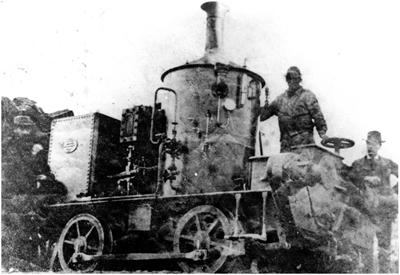
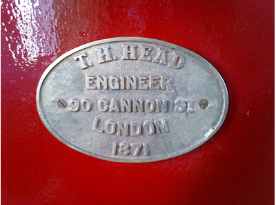
In 1871, T.H.Head engineer of London supplied the Dorking Greystone Lime Company with an 0-4-0 Vertical Boilered Geared locomotive. The diminutive engine was actually built by Head Wrightson & Co Ltd.
The origins of this locomotive were in Head Wrightson’s standard ‘Type 1’ design. In reality a standard ‘factory’ locomotive was a rare beast and in this instance two modifications were requested by the Dorking Greystone Company. These were that sprung buffers be fitted in place of the dumb buffered option offered, and that a 300 gallon water tank supplement the standard 150 gallon version. These extras added £10 to the £435 cost of the engine! The little Coffee Pot fulfilled the simple task asked of it until 1952, before being withdrawn and left to fall into a derelict condition.
In September 1960 Coffee Pot was re-purchased by the then incarnation of its builders, Head Wrightson Teesdale Ltd, and moved by road to Head Wrightson’s works at Thornaby, Teesside. Here the Betchworth exile re-joined two other Head Wrightson products, works numbers 21 and 33 of 1870 and 1873 respectively, both of which had worked out their entire operating lives more locally at Seaham Harbour on the County Durham coast south of Sunderland. One of this pair can be seen on display at the station at Beamish during 2008.

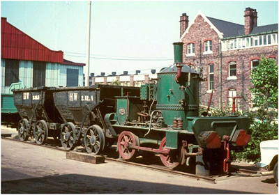
During 1960, Head Wrightson’s apprentices restored the locomotive to what they thought to be its original appearance. They also converted the engine so that it could be demonstrated (with wheels propped clear of the rails) on compressed air. A similar restoration was carried out on sister loco, 21/1870 as seen below at Thornaby.
Offered to Beamish in 1962, the engine remained at Head Wrightson until 1970 when it was initially moved to the British Steel Corporation’s Consett Ironworks in County Durham.
Once at Beamish restoration commenced and limited steamings, including rare passenger trips in converted chaldron waggons (see photographs below), took place with the Coffee Pot, by now repainted into a livery of green and black and still minus the Betchworth roof and handrail additions.
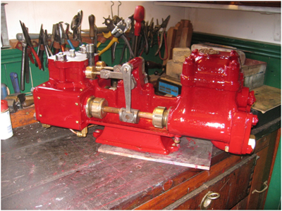
In 1982 Beamish was benefiting greatly from the Manpower Services Commission (MSC) schemes, one being the overhaul of the Coffee Pot to 1940s appearance. Resplendent in a new livery of maroon (as there was no indication of what the Betchworth livery was, other than white lime dust!), the rebuilt locomotive was launched at Beamish on May 31st 1984.
Once again the locomotive’s age became a hindrance to its operation and by the 1990s it was again out of use, stored in the colliery engine shed. A key problem was the mounting of the cylinders and crankshaft directly onto the boiler, numerous leaks developing through the oscillating movement of the valve gear and connecting rods and the difficulties in ensuring that the mounting bolts remained secure.
 |
| Coffee Pot after the 1984 overhaul. |
Conservation Management Plan
For any complex conservation project, the museum prepares a Conservation Management Plan to control the way work is carried out and ensure that this is all thoroughly recorded. In this instance, the report is broken down into all known history of the Coffee Pot, then a summary of the scope of the work required to meet numerous potential objectives (conservation/restoration/overhaul or even leaving well alone!) with a discussion of impact of work, what will be recorded and how it will be recorded (and where).
Head Wrightson – A Teesside Manufacturer
In 1840 Messrs Head and Wright united to form a foundry, based in Thornaby on what we know today as Teesside. Their factory became the Teesdale Iron Works, expanding rapidly through the 1850s and 1860s. Mr Wright left the partnership, his place being taken by Mr Ashby, the name changing to Head, Ashby & Co.
In 1860 a former apprentice from William Armstrong’s famous engineering works in Scotswood, on the Tyne to the West of Newcastle, joined Head, Ashby & Co. Thomas Wrightson quickly added his name to the company title, Head Wrightson & Co. being the result. The firm soon built up an enviable reputation for supplying cast and wrought iron for boilers, railway track chairs, bridges, piers (including an example in the Isle of Man, built at a cost of £45,000) and even ships for the British Navy. It was during this period that Head Wrightson had a brief flirtation with industrial railway locomotive building.
In 1845 the company had employed some 450 men, by 1892 this had risen to 1,200 people, reaching nearly 6000 employees in 1968.
On the 21st June 1890 the company was incorporated, the title changing to the more well known Head, Wrightson & Company Limited.
During the Second World War the company suffered severe bomb damage in air raids on the area. Despite this they were able to remain in production, eventually supplying landing craft in the lead up to the D-Day landings and liberation of Europe in 1944/45.
In the 1960s, conscious of its heritage, Head Wrightson purchased back three of its steam locomotives, built in 1870, 1871 and 1873 respectively. The apprentices at the firm restored these to what was understood to be their original condition before they were placed on display at Thornaby.
One engine was placed on stands, enabling the locomotive to be operated on compressed air. It sat alongside two former Londonderry Railway (later Seaham Harbour) chaldron wagons [sic], each bearing the initials HW – Head Wrightson.
Like so many seemingly unshakable (almost institutional) firms, Head Wrightson was to suffer from an extensive and irretrievable decline through the 1970s. Eventually the Thornaby works, scene of so much production, was closed, the three preserved locomotives finding homes elsewhere, as we shall see later.
The Teesdale Iron Works site was later earmarked for development, but not before then Prime Minister, Margaret Thatcher, had been photographed on her famous ‘Walk through the Wilderness’ on the site.
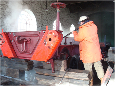
Fortunately many of the Head Wrightson’s records survived and were deposited with the Teeside Archives in Middlesbrough. These include numerous order books relating to the many bridges, piers and railway wagons that the company built. Unfortunately, from the point of view of this project, the 1859 – 1877 order book is missing. This would have revealed the true extent of Head Wrightson’s locomotive output as well as those who purchased them. It probably would not, however, reveal the customer’s motivation for purchasing these particular types against some of the more prolific builders, particularly of vertical boilered engines, such as Alexander Chaplin & Co of Glasgow (whose output totalled some 136 vertical boilered locomotives between 1860 and 1899).
Restoration Diary
30/11/2006 Boiler and cab removed. Rolling chassis steam cleaned (along with HW 33/1873)
 |
| Boiler and cab removed |
10/01/2007 – Frames lifted from wheels and packed. Journals and bearings examined and found to be in very good condition.
10/10/2007 – Graham Morris surveys boiler on this locomotive and HW 21/1870 for preparation of new boiler drawings.
11/10/2007 Extensive discussion between Paul Jarman and Graham Morris re final form of boiler and requirements of museum plus satisfying boiler regs for CE mark. October 2007
05/12/2007 – HLF award announced!
10/12/2007 – Graham Morris visited to do some checks and final discussions pending production of drawings for boiler. Discussed second steam feed (for boiler pump), second clack (as before), location of blower and whistle, provision of a pad for main steam pipe and means by which steam will feed the cylinders. Examined 33/1873’s safety valve as this will form basis of a casting for No.1 – one safety valve to be fitted (Salter type).
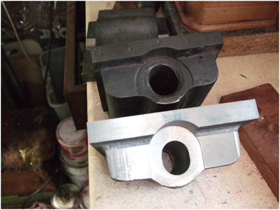
12/12/2007 – Word from Graham Morris: The crankshaft bracket casting is different on No.21/1870 (narrower and generally more slender). So I think we can safely say that the wider cylinder spacing on “Coffee Pot” is to accommodate the sliding gear arrangement. Which also explains the asymmetrical angle iron boiler mounting brackets as they had to clear the repositioned piston rod guides.
19/12/2007 – Dave Sheen completed welding up holes on brake hanger and disengaging lever cross beam. David Young, who is tirelessly overhauling all of the moving parts, will bush and/or re-bore these as required. David collected them for machining and reported that the regulator has been cast, collected, machined and is being painted!
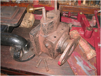 |
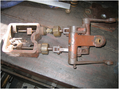
| The regulator valve being overhauled by David Young |
 |
| The original regulator quadrant, note the crack and patched repairs. A new one will be required. |
20/12/2007 – Collated all information on Vertical Boilers from National Boiler Insurance Company volumes, copied and placed with 2nd edition of HS(g)29 (now part of ORR library) for Conservation Management Plan and manual – in preparation…
08/01/2008 – David Young delivered remaining parts, including brake gear and regulator rod. One new pin fitted to brake gear, all new nuts and outstanding spring leaves (DS to supply). David Young making pattern for new slide valves as originals have been made up to size and have de-laminated. This is unacceptable so new ones will be cast and machined. DY making pattern and machining, we will pay for casting. The port faces will require examination. Preliminary inspection shows that some welding up of edges is required, before grinding or filing back true. To be done in engine shed.
 |
| Part of the brake gear, dismantled for refurbishment. |
Easter: What a difference a day makes – we parked No.17 up with some chaldrons on the Friday – the weather looked promising for the weekend, However, by Easter Sunday it was a rather different scene…
From David Young’s workshop… Old and new slide valves, cast from new patterns and machined in David’s well equipped workshop. Hopefully the evidence of disintegrating metal will now no longer be evident on the working locomotive!
 |
| Old and new slide valves |
David Young’s work latest (to 31/12/2007):
• Collect, deliver and consultations: 14 hours
• Dismantle, examine and clean: 8 hours
• Remove old paint: 8 hours
• Machine slide valve faces: 4 hours
• Machine and spot face bolting surfaces: 4 hours
• Make and fit new stainless steel valve rods: 8 hours
• Make studs and overhaul existing studs: 4 hours
• Make and fit cleading: 6 hours
• Overhaul seized valve gear and make new s/s pins, nuts, keys: 12 hours
• Make and fit steam cylinder cocks: 8 hours
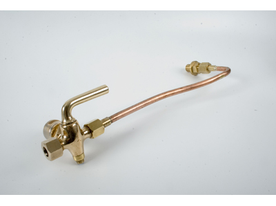
• Make brass water connection and steam pipe: 8 hours
• Pack glands (8) including removing old: 5 hours
• Paint and rub down – 2 coats primer/4 filler/2 final/2 varnish: 30 hours
• Re-assemble regulator, machine and adjust: 10 hours
• Make pattern for regulator bracket: 12 hours
• Make drawing for regulator bracket modifications: 4 hours
• Dismantling brakes and grinding spindle links: 5 hours
• Dismantling and preparing disengaging lever cross rod: 3 hours
• Foundry visit: 2 hours
• Two visits to measure locomotive: 3 hours
• Making and boring two new brake rods to match original rods: 6 hours
• Machining brake arm and making pin bush: 6 hours
• Making pillars, studs etc. for regulator handle quadrant: 12 hours
• Boring brake hangers and making and fitting bushes: 22 hours
• Strip regulator rod and refurnish pins: 2 hours
• Machine regulator bracket casting (new) and assemble: 7 hours
• Paint regulator: 2 hours
• Boring brake shoe carrier (fireman’s side) and making bush: 7 hours
• Paint brake hangers, carriers and rods: 40 hours
• Making nuts and bolts for brake rods, finishing jaws on valve rods: 6 hours
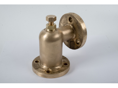
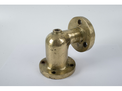
Two views of the steam pump that will be one of two water feeds to the boiler. Made by Hickey of London but to a design by Worthington Simpson:
 |
| View of the steam pump |
08/02/2008 – Conversation with David Young regarding slide valve and steam chest. The cast slide valves are currently being machined and has turned the slide rod to 15/16 inch (from 1 inch) to remove heavy grooving and wear. The rods have also required straightening and the square section that slides in the rod guide has been made true. David and I discussed bushing the casting of the steam chest where the rod passes through, this to be a collared bronze bush retained by the gland packing. This seems to indicate the locomotive being built and run to cost, and due to the potential wear on the original material of the cylinder casting, it is deemed prudent to carry out this work. We are very aware of non over re-engineering the engine unit, however we need to be assured its safe and reliable operation with minimum wear of existing and original components. DY to visit on 11/02/2008 to measure steam chest and test fit of the slide valves and rods.
All refurbished components moved to colliery engine shed and placed on display there pending reattachment to Coffee Pot.
11/02/2008 – David Young visited, bringing machined valve rod spindles and one valve itself. These were tried in the steam chest, marked up for later re-fitting and the spindle guide slippers removed for copying (only one of the two sets required is present). David has agreed to make the pattern for the safety valve, and North East Die Casting at Wolsingham will cast this to the required British Standard. David Young will then machine and make and fit the rest of the safety valve components.
25/02/2008 David Young in to remove lifting links from reverser cross shaft. These are notably pitted and also different sizes on each side!
26/02/2008 Discussed works plates, Salter spring balance and injector with Graham Redfern. He will make the former two and has completed the Giffard injector originally intended for Lewin. We will explore using this on Coffee Pot.
27/02/2008 – Steam cleaned chassis, paying particular attention to spring hangers which were thick with grease. Set heater to dry out frames pending painting. Initial process will be to prime and paint the inner sides of the frames red. The outer sides will then follow (including underside of running plate). Wheels and axles to be painted also, then frames can be re-wheeled pending completion of upper surfaces, bunker and bufferbeams. Tank to be grit blasted and I am investigating a liner for the inside. Once painted it will be placed on the frames temporarily, complete with works plates.
03/03/2008 – PJ painted inside surfaces of frames (Red Oxide). Will overcoat with suitable RAL Numbered industrial enamel paint for durability.
05/03/2008 – David Young hours update
• Making patterns for slide valves: 10 hours
• Trips to foundry (x2): 4 hours
• Machining and boring castings: 10 hours
• Making bushes for glands and restoring: 8 hours
• Machining and truing valve rods: 20 hours
• Prepare Handrail Stanchions for painting: 8 hours
• Removing inner gland bushes: 10 hours
• Machining and fitting valve special nuts: 8 hours
• Painting Handrail stanchions – 8 coats: 18 hours
• Dressing the four lifting links, filing and polishing by hand: 16 hours
• Trip to foundry for Gunmetal casting (x2): 4 hours
26/03/2008 – Work session on Coffee Pot. DS/DY/PJ. Cleaned and painted outside of frames in red oxide, DY tried out reverser arms and keys. These need replacing. The key ways are square ended, suggesting they were formed from Victorian practice of drilling a series of holes then chiselling out the metal to create a rectangular keyway. This was photographed for the records.
 |
| The finished steam drived duplex water pump |
31/03/2008 – David Young in to fit keys and arms for reverser cross shaft. Reported as an excellent fit, drifted into place using a purpose made aluminium drift.
The two lifting arms for the valve gear on Coffee Pot. The arms are keyed onto the reverser shaft using keys set in situ…
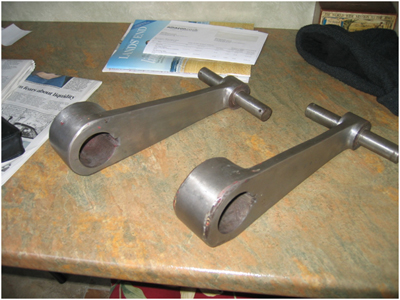 |
| The two lifting arms for the valve gear on Coffee Pot. |
02/04/2008 – Working day with PJ and DY. Outside of frames recoated and first coat of frame red (actually Signal Red) applied to inside surfaces. Reverser cross shaft now permanently fitted and in undercoat. PJ and DY studying contemporary references to investigate ‘typical’ engineering practice for the 1870s.
16/04/2008 – Graham Morris, PJ and DY met to discuss safety valve design and how to manufacture it. Agreed additional thou on seat insert and that the machining for this and pressing it in place would be contracted out. DY will make pattern, machine and make fittings. Spindle to be cast also (all gunmetal).
PJ and GM discussed ashpan and GM measured for clearance. A raised lip is to be fitted, increasing in height at the front to protect the gears and motion. The sides will dip to enable it to be raked clean. The smokebox hinge was discussed and the lid of No.17 removed for inspection. Discussion of hinging this and how to clear the fittings took place and was agreed. A blastpipe and blower ring were also outlined.
Boiler fittings were discussed, DY took away No.17s clack for copying to make two examples for No.1 (in gunmetal). Some fittings needed but should be available from List Brain. Making boiler top ring discussed – casting favoured so costing will be required – this is additional so PJ to seek some separate money for this work if possible.
PJ must contact Vincent Allan re lagging, cladding, fitting boiler down, gear alignment, placing fittings into boiler, making blastpipe and blower, blowdown pipe and arranging pipework for pump and injector. PJ and GM agreed a plan of what is required re water supply for the boiler via pump of injector. Graham Redfern is going to test the Giffard on Sir Cecil Cochrane to see if it will lift water as required – the outcome of this will determine where the injector is mounted.
Components laid out whilst the chassis is painted. The heater takes some of the chill out of the air in this cold building, and warms the metalwork making the application of paint both easier and of a better finish…
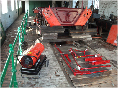 |
| Components laid out |
29/04/2008 – Visited Vincent Allen’s workshop. Also discussed the potential of the Giffard lifting water – Vincent thinks 3 feet should be ok. A full tank may help! This will give a head above the injector water intake.
02/05/2008 – Continuing rubbing down undercoat (3 red oxide, 3 undercoat to date) ready for at least one more coat of high build undercoat. David Young continues to make the patterns for the clack valve, safety valve and numerous flanges.
Conversation with Graham Redfern re the works plate and Salter spring balance for the safety valve. Progressing well.
12/05/2008 – David Young applied penultimate coat of top colour. Also delivered safety valve patterns (core and valve) which are superb. He is finishing patterns for the clack valve and matching flange plates. First coat of signal red applied to buffer pads.
13/05/2008 – David Young in – applied final top coat. I cleaned and painted one set of springs, used heatproof matt black paint (Craftmaster) as gloss paint may effect the movement and future lubrication of the leaves.
 |
| David Young shows off his superb handiwork in painting Coffee Pot’s frames. |
15/5/2008 – David Young and I erected tent over engine to allow varnishing to commence over weekend. Some rubbing down also took place.
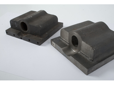
Two views of the safety valve casting pattern. The shape is self explanatory, whilst the L shaped patter is to enable two cores to be made and placed together in order to form the core of the valve itself. These have been made from materials recovered from the Beamish Waggonway’s firewood pile! The complex curve was formed by cutting segments, chocolate orange style, then gluing these to form a lobster back shape. This is then machined and hand worked to form the smooth curve of the pattern. David has produced all of the patterns for this project and his skills with wood seem to be every bit the equal of his skills with metal! Gunmetal castings will be made and machined for final assembly. I hope the Blog will have some pictures of the casting process in due course.
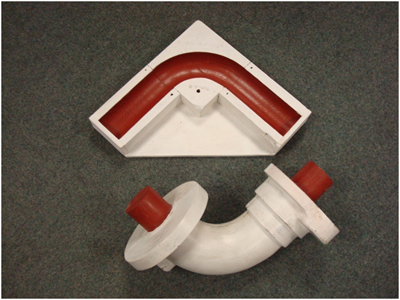 |
| View of safety valve casting pattern |
 |
| View of safety valve casting pattern |
13/05/2008 – David Young in – applied final top coat. I cleaned and painted one set of springs, used heatproof matt black paint (Craftmaster) as gloss paint may effect the movement and future lubrication of the leaves.
15/05/2008 – David Young and I erected tent over engine to allow varnishing to commence over weekend. Some rubbing down also took place.
20/05/2008 – Tent dismantled and David has fitted some parts, including the reverser. PJ fitted springs after cleaning and inspection. These are thought to have been new in 1984 and appear in good order.
21/05/2008 – Prepared loco for re-wheeling. Scraped rear of driving wheels, set up axle boxes and fixed jacks. The initial fit was poor – the fireman’s side front axlebox was tight and the drivers side would not fit the journal properly. This was removed to investigate. Though the boxes had been previously removed and inspected, they were found to be in filthy condition with grease and dust evident – partly a problem with the dust that blows into the shed if the inner doors are not closed properly. Re-wheeling was postponed in favour of stripping and cleaning all the axle boxes and journals. The oil lids were removed and cleaned, oilways unblocked and flushed with petrol the journals polished. The troublesome box was found to have a bearing in reversed position, a situation quickly remedied. New wicks will be fitted once the loco is a rolling chassis once again. Also moved water tank onto a flat wagon for restoration.
22/05/2008 – DY and PJ started at 11am – more cleaning of axleboxes and measuring up for new retaining pins (3/8 steel round bar). DY cleaned rods and roughed original finish ready for new colour to be applied (SC Crimson – the same as the locomotive – no red rods here!). The disengaging lever crank arm is a very loose fit, so DY will re-bush the crank and file true the footplate mounted pin. This should ensure a positive action when engaging/disengaging the drive pinion.
30/05/2009 – Visited foundry with Dave Young and Dave Sheen to deliver the patterns made by DY fro the safety valve, clack valve and inserts. Saw induction furnace in action. Total price £1025 –any readers want to sponsor these?!
02/06/2008 – Dave Young came in to fit brake hangers and also to finally fit the bell crank for the disengaging lever. This required subtle (!) grinding of the frame edge to accommodate the fixing pin. The hangers are located centrally but this has revealed the brake blocks will not locate properly on the wheels. Consideration is now being given to making a new pattern for the blocks and casting to suit the trued up brake hangers. A softer material can be selected to reduce tyre wear and spares will also be obtained. DY has discovered many inconsistencies in pin size across the loco, and the brake gear is no exception!
20/06/2008 – DY and PJ refitted coupling rods. Cotters were removed and bearing split to assist with this. Cotters have been left loose until trial runs take place, so as to allow for adjustment as required. Gear wheel also refitted, using a temporary beam to hoist it from. Though not particularly heavy, it is awkward to handle and this method spared the new paintwork any unwanted chips or scratches. DY measured up the key-way for a new key to be made.
23/06/2008 – DY finished assembling and painting the brake gear whilst PJ refitted and painted the steps. It is noticeable, now that we have shiny paintwork, just how dusty the engine shed is and we may need to consider sealing the floor somehow to reduce the dust evident in the shed.
Two views of the nearly finished chassis, now featuring the coupling rods an footplate steps.

04/07/2008 – Little progress at present whilst DY is on holiday and I have been taking Puffing Billy on its travels. However, work on the boiler continues and we will shortly refit the buffers and move the cylinder block into a more accessible location.
The colour of the buffer beams and buffer block has been causing some thought. It is probable that when new, they were painted the same colour as the frames, or even black. However, to offer some compliance with post-Victorian practice, I decided that they really ought to perpetuate the red shade likely to have been applied at an early stage. But what red should we use?! Initially a signal red has been applied (the same as the inner frames are painted). However, in natural light this appears to be very orange, and not consistent with the quality Victorian appearance that we feel is so important to the project and that has been worked on so hard elsewhere.
Whilst Puffing Billy was running at Tyseley last weekend, I commented that the buffer beam colour on the locomotives outshopped from the works there was just what we needed. Bob Meanley, CME there, offered that this was carefully matched to some original colour found on Rood Ashton Hall, and is described variously as Chrome Red or Chinese Vermillion. A search online and in the museum’s library has produced some variants, to we may take Bob up on his offer to supply a tin of suitable colour for the project. The shade is a browner shade of red, with a superb lustre and which should suit Coffee Pot very well indeed. Photos from the Tyseley event should appear on my other blog ‘Beamish Transport Collections News’, which is currently being put into place.
11th July 2008
A study trip was carried out to the former Dorking Greystone Lime Company Quarry at Betchworth, Surrey. The quarry has been filled-in in recent years, now bearing little resemblance to contemporary archive footage. Some of the kilns remain, as does the building adjacent to the site of the standard gauge engine shed. Viewing the site (and allowing for the impact of 20 years subsequent quarrying and the land-fill thereafter), it can be readily appreciated just how steep the standard gauge tracks up from the exchange siding with the main line, and reversing up into the quarry, really were. That Coffee Pot was allowed to coast in neutral down these grades makes the operation all the more impressive (foolhardy?!).
Below: This view shows the current Network Rail lines, with a non-stop westbound service approaching. Immediately behind the railings to the right is the route of the first reversal of the quarry line. There is still a Network Rail siding in situ, once surely traversed by the quarry locomotives.

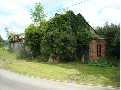
Below: This is the site of the engine shed. Two buildings were provided, one a lean to on the building shown below (see the change in guttering) and one just beyond, where No.1 was eventually stored. The workshops at the extreme right are now private dwellings.
Below: Looking out from the quarry, the parapets of the bridge which carried the Pilgrim’s Way footpath over the narrow gauge lines being visible in the foreground. The remains of the Hoffman Kiln are clearly and dramatically evident.

Below: The filled in quarry as it appears today. The removal of the material to create the hole must have been carried out almost entirely by the steam locomotives working on the quarry system, but a few wagon loads at a time!

16th July 2008
David Young and David Sheen assisted in relocating a 1 ton gantry crane into the engine shed. This will be used to lift the buffers into place and also raise the cylinder block to a suitable height for attention. David Young removed the handbrake handle spigot for re-polishing to a bright steel finish and also fitted the refurbished brass collar to the handwheel underside.
18/07/2008 – David Young and PJ refitted buffers using gantry crane brought down from tramway workshops. This was heavy and awkward work (on account of the buffers being sprung!). One wooden buffer block, onto which the buffers mount, is showing signs of movement as a result of the weight of the buffer being refitted, and this is being monitored (back left hand side).
21/07/2008 – DY and PJ moved gantry crane in order to reposition the cylinder block and crankshaft casting. Both now placed on pallets at convenient working heights. DY has polished brake handle to a bright state. Off site DY has machined the two clack valve castings and is preparing to start machining the ‘innards’. PJ purchased a valve to be modified for use as a blower, has approved the patterns for the worksplates and had further discussions with Graham Morris regarding the smokebox and the hinged arrangement required for cleaning tubes and top tubeplate inspection.

25/07/08 – DY and PJ set to on reattaching the loose buffer beam. However, like so many jobs, investigation into the fault revealed a rather sorry situation. It seems the bolts retaining the buffer beam to the loco frames have suffered from the corrosive effects of the tannin in the oak blocks. As a result, all attempts to tighten or even loosen these bolts failed. As there is a substantial crack in the block, it was decided to remove the buffer to explore the extent of this failure. As a result the oak block was condemned! Two bolts were removed, using an angle grinder on one and hacksaw on the other. We will have to remove the block and send it for replication.
Fortunately Anthony Eveleigh (who built Puffing Billy’s oak frames and the wooden waggonway) was at Beamish working on the Lamp Cabin. We will now remove the block and send it to him to copy. We will use square headed bolts (ex Port of Sunderland), rethreaded and inserted into the new buffer beam (cauterising the hole first to seal the tannin). A square nut will also be used, replicating what was probably originally fitted to the loco.
PJ cleaned and scraped back the bunker and applied a coat of grey primer, pending two coats of gloss black to complete this area. A redundant bolt head was also cut away.
28/07/08 – DY and PJ finished removing the cracked buffer beam, methods utilised a hacksaw blade and an angle grinder plus hammer and chisel! Anthony is going to try and secure some kiln dried European Oak to replace this. PJ applied first coat of black to bunker interior plus the footplate edges. Tank should be sandblasted this week!
21/08/08 – A busy week of progress, which has seen the valve rod guides completed by David Young, the cylinders cleaned and the first coats of paint applied and the buffer beam removed to Monmouthshire for replication.
10/09/08 – David Young has completed the painting of the cylinders and crankshaft bracket. He has also fitted the refurbished drain cocks and pipework and painted the gear wheel on the driven axle. A tent was erected again to allow varnishing of parts to take place. The steam chest covers are being prepared for painting and burnishing, and the tubes that enable the slide valve springs to be enclosed are being removed (these were not fitted originally, but will be kept in case they are required – though the new slide valves should mean that this is not necessary). We are still waiting for the estates department to shot-blast the water tank as this is required for painting before the weather deteriorates further.
15/09/08 – Dave Young and I decided that the buffer beams do not look ‘right’ in signal red, and after seeing how Bellerophon’s looked in black, we repainted one end to suit. One side matt black, the other gloss black. Gloss won and I repainted the matt one in the evening, as well as finally hanging the notice board in the engine works porch. Tomorrow should see the reprinted (waterproof this time!) exhibition hung. Meanwhile, David is making an electric powered tumbler cabinet to clean the bolt heads for the steam chest covers (which will be ‘bright’, i.e. polished metal) and preparing the covers themselves. This has seen the tubes that held the slide valve spring removed, as these appear to be redundant. However, we will be able to refit them if needed and the slide valves have been milled with a flat sliding surface to enable this to be modification to be carried out if required.
Two mysterious inlets are fitted into the steam chest casting, these causing some confusion to David and I. They appear to be for drain valves to be fitted, and pipes run down the boiler and clear of the crankshaft to substantiate this. It is also suspected that Coffee Pot will be a very wet engine, as the steam pipes and cylinders are not lagged. However, inside each steam chest is a copper pipe connected to the inlet, indicating it is for lubrication. How the oil travelled up the pipe is not clear, nor is it likely it was pumped there from the mechanical lubricator fitted in the 1970s and refitted in 1984. As there are now ‘brass onion’ displacement lubricators fitted to the cylinder covers (and these were installed in the 1970s) plus the regulator live steam lubricator, oil will be plentifully available. It is possible that the 1984 work failed to realise the lubricators were a 1970s addition, so fitted additional lubricators as a precaution. As the 1871 spec does not feature the steam chest lubricators or rains (whatever they are!) we will not refit them now. Operating experience may prove this to be incorrect, but we shall have to wait until next year to find out!
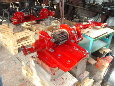
Below: Two views showing the completed cylinder assembly and crankshaft casting and shaft. Note the refurbished cylinder drain cocks (with lovely three way cock), the slide valve guides now completed and the interior of the steam chest (noting the copper pipe referred to in the text).

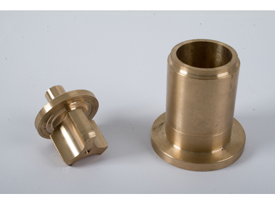
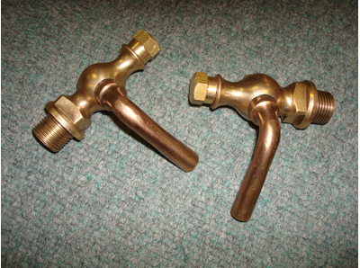
Below: This is Coffee Pot’s clack valve. The first view shows the new valve body )one of two for this engine), completed to a superbly high standard by David Young, who made the pattern as well as machining the body and making the valve and sleeve that fit inside. The clack (or check) valve enables water to be admitted to the boiler under pressure, but prevents the contents of the boiler coming back out – it is essentially a one way valve. Sometimes these valves stick, and to prevent steam exiting via the injector and feed pump inlet pipes, or to isolate the clack valve for maintenance purposes, a long bolt is fitted to screw the valve down onto the seat. The second photograph shows the liner/seat as well as the floating valve itself. The third view is of an original clack valve, as fitted to Head Wrightson’s No.33 (Seaham’s No.17), also at Beamish. A spare to this has also been manufactured, making three in total.
Below: Three views of the refurbished slide valves, which control the admission and exit of steam in the cylinders, enabling the double action of the engine to work. The valves were in a poor state and David Young made patterns for new castings, which he subsequently machined and fitted to refurbished valve rods (which had become badly pitted). The photo shows the new valve fitted to the valve rod, plus two views of old and new valves for comparison. The originals had worn to such a state that they had previously been repaired by screwing on shims of metal. These have deteriorated and the concern we had was that the shims might detach themselves in operation, damaging the port faces of the cylinder casting. The lock nuts (brass and steel in the photographs) enable the valve to be adjusted on the rod, to give an even timing to the valve events (or regular ‘chuffs’ if you like!).


Below: These views show the drain cock assembly. Unusually for a railway locomotive, a three way single cock is used to control the egress of water and steam, meaning that the plain pipe from the upper end of the cylinder is always under pressure when the regulator is open. David Young refurbished the existing pipework and cocks and these have been refitted to the cylinder (as seen elsewhere). What is of particular interest is the copper pipework. This pre-dates extruded pipe and, as can be clearly seen in the photograph, it is formed of rolled flat section, then silver soldered together to form a circular section. This is another small, but fascinating part of the manufacturing process evident on a locomotive built when sailing ships were still common and Queen Victoria was still well ensconced on her throne.

Below: A view of the newly painted black buffer beams. This scheme appears to much more in keeping with the locomotives pedigree and once toned down in use, will suit the crimson livery very well.

Below: One of the specially commissioned notice boards for the engine works. These will convey much more information about the shed and the locomotives and work within. It is hoped to also feature period adverts for charabanc trips and the like as well!

We have now reached mid-October and whilst there has been a continuing flurry of progress on Coffee Pot, it has tended towards work similar to that carried out earlier on in the project. However, in order to give the regular reader something new to see, I have posted some photographs taken over the last seven days showing progress on painting the water tank. As I write this is now rubbed down ready for varnishing. There is something of a race against time with this as we want to have the painting completed before the really cold weather bites us in November.


Also shown is one of the burnished (by David Young) steam chest covers. These (there are two) were in a rusted state and had previously been painted. We felt, however, that the burnished finish would be appropriate. Notice also the brass cap on the cover. This replaces a short trumpet like attachment that probably housed a sprung mechanism to keep the slide valve against its face. Unless we find otherwise (in operation), we have decided not to incorporate this non-original fitting.
02/12/2008 – There hasn’t been much to report on the blog in recent weeks. David Young has continued preparing tank fittings and other smaller items for the locomotive. We have also agreed the programme of final works to be carried out, this will include steam testing and fitting the boiler into the frames and will be carried out by well known and admired traction engine restorer Vincent Allen (see photo below for his last project!). Boiler construction continues at Israel Newton & Sons whilst various orders are in hand for sundry fittings for the Coffee Pot. Notable amongst these are the replica works plates, currently with the foundry.
Much work on the transport collections is ongoing elsewhere and you can find latest news and photographs on the Transport Blog.
14/01/2009 – Little progress has been possible in recent months. Mechanically Coffee Pot is 95% complete. We are now waiting for the boiler from Newton’s. This is expected in April. The boiler and locomotive will move to Vincent Allen’s workshop for steam testing, assembly and fitting of pipework etc. The worksplates have been cast and are now fitted and look very well. DY is to make a copper ball for the water level indicator. Tell-tale lubricators have been ordered to provide a full set for the coupling rods. Some outstanding painting jobs will be attended to once the warmer weather arrives. Work in the shed has concentrated on the Marshall bottle-framed engine, which is once again complete and ready for testing on air.
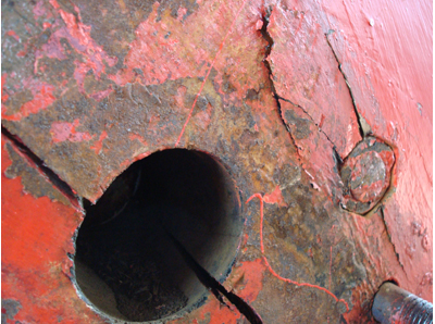
10/02/2009 – With the assistance of Davy Sheen, the cylinder mounting brackets were removed from the boiler. All but one had to be burned off, with one shearing off after a blow from a hammer. Given this located into the seam space, it vindicates our decision to blind bush all such mountings in the boiler shell ensuring steam tightness and integrity with or without such fittings in place.
12/02/2009 – Despite the snow, we have had an eventful day today regarding Coffee Pot! As I write these notes, the staff have been sent home and the museum lies under a crisp white blanket, if Coffee Pot could steam, I would light it up and take some photographs!
This morning David Young and I carried out a long planned operation to reunite the water tank with the chassis and relocate the cylinders and crank axle onto a trolley for onward movement to Newton’s. This task was made much easier through the assistance of an unemployment scheme who are working with me on the water tower and coal dock (see the transport blog for 2009). By manoeuvring the engine, I was able to lift the tank with our forklift and place it onto the frames, a job made much simpler through the use of a bespoke lifting beam made by David for the purpose. The engine therefore made a brief appearance outside and the crimson livery looked gorgeous against the snow. The photographs below were taken on my phone so aren’t the best quality, but they show the job just before the tank was put in place, and reveal a very proud David with the engine he has done so much to put back into working order.
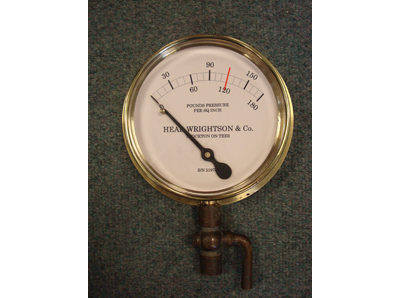
David has also completed the safety valve arm and linkage and I hope to studio photograph these shortly. Further news came from the company making the very special pressure gauge for Coffee Pot, which should be delivered shortly.
So what next? Well, various parts need delivering to the boilermaker and there are numerous odds and ends to attend to. The bulk of the outstanding work will relate to the boiler and pipework, which Vincent Allen should be able to start in April.
The new worksplates have also been fitted, these being replicas of those fitted by T.H.Head as selling agent for the locomotive. Graham Redfern produced the patterns following extensive discussion and intense study of some very aged photographs! These are brass castings and have been securely fixed on the water tank sides. I suspect we will opt for a black background, rather than leaving the plates bare as they appear here.


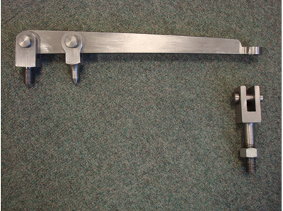
16/03/2009 – After a quiet period regarding Coffee Pot No.1, there has been a sudden burst of activity on the locomotive and its boiler, which is pleasing as it marks the start of the home straight! Tomorrow I am visiting the boiler so there will be lots to report later this week, so for now I thought a brief update might be appreciated. As ever, David Young has been busy with the fittings, his latest masterpiece being the safety valve arm. This required considerable milling work as well as strict adherence to the drawings. Dave also converted the test cocks for the boiler water level so that they discharge downwards.
Industrial Boilerhouse Supplies (who own Heritage Steam Supplies) have delivered the rebuild pressure gauge. Done to my own sketches and based on contemporary practice (as we cannot enlarge the 1870s photographs sufficiently to be able to see the face of the gauge!) there may be an element of artistic licence with the lettering but it certainly makes for an attractive gauge perfectly in keeping with Coffee Pots vintage. This illustrates those areas where one has to apply knowledge and judgement rather than being able to slavishly copy original practice. Needless to say the gauge is calibrated and certified as such. The cock below will no doubt pass through David Young’s hands for refurbishment!
Below are three images showing the safety valve lever in steel, the bronze test cocks, the blower valve and the pressure gauge.

On Sunday we conducted a brake test using No.22 and Coffee Pot’s rolling chassis. I wanted to see what force it could exert on the downward gradient into the engine shed, the steepest part of our line. A rolling test, light engine (chassis?!), proved the effectiveness of the brake, so the next test was carried out with No.22, with the brake having to stop the pair on the falling gradient and then hold them. This worked very well and particularly so given the lack of weight (boiler, cylinders, motion etc not being fitted). It is a testament to David’s work in replacing the pins and linkages as well as the sense in having a management plan for the engine that allows safety critical works like this to be carried out without harming the originality of the locomotive.
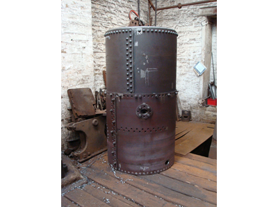
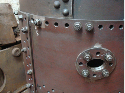
17/03/2009 – Today I visited the works of Israel Newton & Son to deliver Coffee Pot’s cylinders, mounting brackets. Crankshaft mount and sundry fittings. Progress is impressive and the photos show the boiler to date. The final riveting is shortly to take place on the hydraulic riveter which will then be followed by working on various holes and mounts for the fittings. It is terrific to see this in the flesh, having so long poured over old photographs, the remains of the originals and, of course, Graham Morris’ superb drawings. A few tweaks have been made here and there but it certainly provides impetus to get the locomotive into service at Beamish as soon as we can!


Fascinating.Can I query something?.Reference is made to coffee pot 17 and Seaham harbour but the loco under restoration looks nothing like number 17. Photos of 17 when new held in the Seaham lifeboat museum show a much larger loco with outside cylinders and a fully enclosed permanent cab with brass “spectacle” windows and a brass plate bearing the number 17. The vertical boiler is partly Enclosed in the cab. Altogether a different locomotive. It looks to be about the size of an LMS pug 040. differences show it to be a much more sophisticated coffee pot. Could you possibly comment?.RegardsWalter Snowdon
Hi Walter – the post you are looking at is pretty old now and dates to the restoration of our Coffee Pot No.1, built by Head Wrightson in 1871. This loco has been in operation since Easter 2010 now and if you search the blog for ‘Coffee Pot’ you should encounter many photographs of the engine working at Beamish and elsewhere. There are three locos built by Head Wrightson preserved, as the post you commented on describes. No. 16 and 17 are ex Seaham, whilst No.1 is ex Dorking Greystone Lime Co. It carried no works number and was supplied via agent T. H. Head. No.16 in the Seaham fleet was works no.21 of 1870 whilst No.17 was works number 33 of 1873. All three locos found their way back to the Head Wrightson works in the 1960s, for restoration and display around the factory site. No.1 and No.16 are of the earlier type, with cast iron frames (made in one piece) and vertical cylinders. No.17 was of a later variant, presumably easier to construct, with plate frames and conventional locomotive-type cylinders. It is no larger however, so this must be an optical illusion! No.17 was supplied to the Londonderry Railway for use at Seaham Harbour, later being absorbed into the Dock Co fleet in 1899. It would appear to have received a substantial rebuild in the early 1890s, where a cab of typical Seaham Harbour Engine Works (SHEW) was fitted. Various other features no longer present are also evident at this stage. In the 1950s the engine appears to have suffered a rear end shunt, sufficient to require a new rear buffer beam and a shortening of the frames by about six inches. The boiler on No.17 is marginally taller than No.1, though is narrower. I do not know when 17 lost the cab, but it was certainly gone by WW2. There are therefore photographs of this engine in three guises, and copies of these can be seen at the East Durham Heritage Centre. There are numerous other detail changes over the years all of which have been identified pending the day we restore No.17 to working order (in 1890s condition complete with cab and full-length frames).
If you follow the blog chronologically you will see the culmination of No.1’s restoration and also the cosmetic overhaul of No.17.
I hope this information is of use?! Paul
Facinating. I would like to build a model of No1. but have no plans as yet. To enable me to draw up plans could you give me the diameter of the boiler? I could then scale the rest from my desktop.