
T&I News update mid June 2014…
A slightly different weekly report, just to ring the changes on endless workshop views that otherwise rather dominate the blog! You can also find new galleries here too – covering trams in Prague and Motor Rollers in various shapes and sizes – this latter one will continue to grow and be added to.
Sunderland 16
I thought readers might appreciate some background to the current and protracted overhaul of Sunderland 16s Peckham P35 truck. We have encountered significant delay in what was hoped would be a quick overhaul, and whilst the re-tyred wheels, tested springs and refurbished motors stand ready for fitting and testing, the truck frame and suspension itself is causing us some head scratching! We are lucky to be able to draw on the professional services of Peter Barlow, from the Beamish Tramway Group, aided by fellow BTG members Les Brunton and Mel Whatmough, plus the workshop staff Brian Williams, Tom Dorney and Chris Armstrong in carrying out the diagnosis of the faults and remedial action.
We are basically finding that the long and hard life this truck has enjoyed is now manifesting itself in a number of fundamental problems that it is our privilege (!) to address! It perhaps also explains something of what must go into even a relatively straightforward overhaul and is perhaps at odds in terms of focus, with what you might read on the internet regarding tramcar overhauls, intervals for intervention and engineering/curatorship. And remember, 16 has had a major restoration (almost construction) and several years hard work – just like it would have for Sunderland – and it requires quite extensive engineering input to ensure the next several years are trouble free…
The key issues are:
- We are using old material that has been repaired and re-repaired over a long working life
- The repairs were not meant to last this long! Applied in the 1940s and 50s as first aid, not a cure!
- The truck frame has been twisted, perhaps as a result of an accident in Leeds when it worked there
- The previous contract overhaul of the truck did not address some fundamental shortcomings
I have used the correspondence by e-mail between Peter, myself and Andy Bailey at Crich as a basis for this quick wander through two of the key elements of work being carried out at the moment, with thanks for their clarity in writing (which made this process much easier!).
On the trammel and spring hangers:
The trammel has been modified to take account of the offset spring mounting holes so we can now measure up for replacement wear plates with respect to the wheelbase centre lines through the horn ways. Chris is looking at ways to manufacture a gauge plate that will fit over the axle boxes, much as the pendulum, so we can replace the wearing surfaces on either side to centralise the box in the horn way. During cleaning and comparison of the 16 spring links, it became apparent that the hole centres have wandered off dimension so we are looking at restoring these to a common length to make sense of the 4 longer links we need to level the springs on the distorted side frame.
Below: The trammel in place, fitted off the spring carrying eye-holes and adjustable to enable the centres to be measured per Peter’s description. 
Below: A view through the hornways of the truck at its No.2 end. Note, very faintly, the line across the centres of the spring eye holes.

Below: Throughout the process of assessment, spring testing was taking place in the machine shop using the bending press adapted with a jog to hold the springs and finer gauge to measure the deflection and enable this to be compared to other springs of the same rating.

The nominal dimension for the horn is 5.800 inches, and new wear plates can be made to produce that gap symmetrically about the centre line of the horn way.
The axle box dimension should be 5.75 inches to give a running clearance of 50 thou. (ideally)
I think the well known solution of using a grinder (carefully) for the final fit when the frame is lowered on to the axles (less springs to start with) should be ok. Using the gauges to set up the wear plates should ease assembly, and ensure that the wheel base is the same both sides!
At the next lift you can be ready if necessary to change all the horn wear plates to bolt on type as original, so that wear can be taken up by inserting shim packing behind the plates. I’m assuming that the other work we’re doing will stop the axle boxes from tilting and causing heavy offset wear.
On the Pendulums (in response to information from Andy Bailey at Crich)
The Pendulums enable the axles a certain amount of sideways movement, important when longer wheelbase trucks are negotiating sharp curves in the track. These contain the roller bearing axlebox, which itself can move up and down against the spring pressure to provide the primary suspension. 16 has never ridden as well as 264, and the truck under 16 was overhauled, from the worst remains of two trucks (the best are under 180 at Crich which is the only other tram to have this type of truck and was restored long before 16’s restoration was even conceived!). This contract work seemed not to have been done entirely as well as it might have been, and allied to a working life of wear and repair has lead to some hefty welded repairs appearing on the pendulum frames themselves.
Continuing Peter’s correspondence:
I think there is a significant difference in the pendulums between the P22 and P35 truck variants. [we have various drawings, none of which agreed with the tram itself]. The drawings coincide with what I can see on [Sheffield] 264’s P22 truck, and clearly show the pendulum suspension point on top of the axle box. The top of the P35 axle box is a plain convex surface and the corresponding part of the pendulum is concave. There is no sign of any sort of groove across the top of the axle box curve or matching shape in the pendulum.
Below: This what they should look like! These are 180’s during a previous overhaul at Crich.
Below: And here is one of 16’s – it isn’t clear here as the pendulum is inverted, but there is extensive welding around the corners where and a generally untidy appearance.

I have not yet made the measurement, but at a guess the centre of the radius more or less coincides with the centreline of the axle giving rotation of the pendulum about that point rather than the top of the axle box. Currently without a curved spacer (bearing) the pendulum cannot rotate because it is sitting on the shoulders either side of the radius. Also the ribs down the edge of the pendulum that contact the axle box may have been built up too far at some time as there is very little clearance to allow rotation.
Further to this, Chris started to clean the old welds up, and found extensive cracking.
Below: A sideways view looking into a pendulum and showing how it rests on top of the curved top of the axlebox. Refer to the comments above regarding the lack of ability for the two curved portions to interact and allow the pendulum to swing (left – right in this view).

Below: A corner face of one pendulum showing the removal of weld repairs and evident cracking in the grooves where Chris has been chasing them to try and eliminate them before repair.


Just a couple of pictures to show what came to light when Chris started to clean up the welds on the pendulums [see photo above]. The crack found runs from the corner where a previous poor repair had taken place right up through the weld and the parent casting to the top edge. One picture shows the exposed ground surface and the second shows the back where the filings had congregated along the line of the crack (running round the edge of the weld to the right) following the flux concentration….. Magnetic crack detection the cheap way.
My thought at present is to clean this out completely, along with the so far apparently rather shorter crack at the other corner, then have a go at repairing the shorter one. Chris and I have worked out a method to try a weld repair, and if successful then we have a go at the bigger one. If the whole lot falls apart, then we will have to go out to a specialist company who have material analysis capability and can say if it is worth the cost. The steel casting looks a bit crystalline in few places where it has been ground…
Fabricating new would also be a contract job for someone with cad and profiling capability. I think only 3 different parts would have to be made, the U shaped side, the bottom trunnion and the bridge piece at the top. A top, two sides and two trunnions welded together would make a new pendulum.
4 tops, 8 sides and 8 trunnions would replace the lot!
So there we go – an explanation of why 16 is taking so long to overhaul! We are now faced with the option of trying to repair the cracked pendulums, which are cast steel. These might take a weld repair but ideally need pre-heating to try and obviate further cracking caused by the heat applied during the welding process. Chris will try on the worst, but if we cannot get a satisfactory result we really only have the option to replace with new, having these drawn and specified in CAD, fabricated, welded and then tested (so as to comply with the need for traceability with such rolling stock under our SMS) before being fitted to the truck. This will be expensive…
A salutary lesson in dealing with old repairs then – and a warning too to all those who have equipment that has been life-extended to keep it operational. We know for sure that the ex Blackpool trams we have dealt with in recent years have abundant examples of such repairs, so never let anyone tell you that they have years of life left in them, because they don’t – not without a lot of workshop support! It is a tribute to Blackpool, like other tramway workshops in the 1940s and 50s, who managed to extend the life of their operational fleets so far beyond their natural lives, and did so in a manner that has served us well, but with increasing mileages and usage, we can no longer rely on this extended working life in trams (and railway rolling stock) and therefore have to build it in from scratch. Painting them is the easy bit…!!!
Changes at Rowley Station
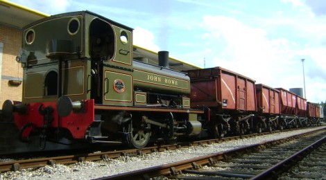
With Vulcan reaching the end of its hire period this Sunday, we now look to the next locomotive for this season’s Rowley weekend operation. This comes in the form of 1908 built Andrew Barclay 0-4-0ST ‘John Howe’ from the Ribble Steam Railway. All being well and subject to final exchange of agreements, it is earmarked to fulfill the rest of 2015’s operating season. We have another locomotive pencilled in, to carry us through to Dunrobin’s arrival later in 2015, this being the same one as we hoped to have from Easter this year. Meanwhile, here are some photographs of John Howe – another petite and pretty Barclay (and the sixth Barclay to visit Beamish in recent years: No.22/WST/Colin McAndrew/Salmon/Jack preceding it).


From the Ribble Steam Railway Website (from where the photographs were also taken, with thanks):
The loco was ordered in 1908 by Howe’s Plaster Works, to work between the private sidings (Howes Sidings Box) on the Settle & Carlisle near Cumwhinton, in Cumberland (as it was then), and their works at Cocklakes. This private branch contained quite a severe gradient up to the works – of which little trace is left today. Howes Plaster Works later became “Carlisle Plaster Co” and later part of British Gypsum.
In the early 1970’s Steamtown in Carnforth were looking to obtain some smaller locos that were more econmical to use than main line machines, to operate their footplate rides.
The loco was purchased along with a number of sister locos, and was taken to Steamtown, Carnforth for preservation. They had been stored in a shed for a number of years, and it is recalled how thick the white Gypsum dust covering the engines was before they left
Upon arrival at Carnforth, the loco received attention to the boiler, and was painted in Campbeltown & Machrihanish North British livery.
The holes below the existing buffers previously house a set of secondary buffers that would match up with the small wooden wagons that were used in Cocklakes.
http://www.ribblesteam.org.uk/exhibits/steam/1-andrew-barclay-1147-1908-john-howe
New additions to the collections
The Bill Etherington sale took place on Saurday June 14th, run by Cheffins and selling off the large and varied collection of items collected by the late Bill Etherington. We took the opportunity to purchase a small number of items that fit in with our plans for visitor engagement and site operation including road maintenance items that will be very useful in the future!
As well as the items below, a Fordson Super Major was also purchased for use on the farm, dating from 1963 and which will provide additional period ‘power’ in place of the modern plant that sometimes has to be used around the Museum on farm duties.
Below: First we have a heavy duty horse drawn stone cart with heavy duty tyred wheels (not a shrunk on hoop). The body tips and the ‘greedy board’ side extensions are removable too. It will be finished in the red wheels and shafts, blue body livery we use for the unprovenanced equipment that forms the ‘Beamish Rural District Council’ fleet of horse drawn maintenance implements.


Below: I have wanted a road grader for the collection for some time, and this example, of the ‘Whites’ type, has now joined the road maintenance fleet at Beamish. The blade is adjustable in a number of planes and angles. These graders were common in the USA and Australia and only really found favour in the UK during WW2 for airfield construction. The origin of this example is unknown though it has appeared at Cheffins on a previous occasion.


Below: This is the first example of the legendary ‘Grantham Series’ of motor rollers introduced in the late 1940s and which overnight revolutionised the product range of Aveling Barford (the amalgam of Barford & Perkins and Aveling & Porter created in 1933). This is of the GB type, considered a large ‘small’ roller and more can be found in the Trade Catalogue section of this site. It is serial number GB1254, built in 1973 (though to a design almost unchanged from the 1940s) and is fitted with a Petter diesel engine, 3/4 length canopy and was registered as OPT 595. The plan is to overhaul this roller and use it on site for road and path maintenance as an alternative to the hired in modern rollers which we currently have to use. Quite a lot of roller for £850!


Below: Our consignment, safely arrived at Beamish…


Hello Paul,
Some really interesting stuff here (as usual!) but I was puzzled by the construction date and registration number of the Aveling Barford ‘Grantham Series’ road roller you have purchased. You said: “It is serial number GB1254, built in 1973 (though to a design almost unchanged from the 1940s) and is fitted with a Petter diesel engine, 3/4 length canopy and was registered as OPT 595.” Surely any road vehicle built and registered in 1973 would have a registration number ending with an “L” or “M” suffix? Is the registration not original, perhaps, or is the date of manufacture not 1973? Sorry to appear pedantic, but I know from experience that building dates and works or registration numbers don’t always tally!
Best regards, Jim Scott
Hello Jim – it is entirely possible that it is older – something to research when I have time. The auction catalogue states 1973 and it is a plausible date, though would have been when AB were part of Leyland (from 1967). As and when I get around to delving deeper into the records, I will report accordingly!
The registration OPT595 was first registered by Aveling Barford on 24/08/1953, according to the DVLA.
Curiouser and curiouser cried Alice!
Hello again, Paul,
I’ve just done some digging myself, and have found that, according to this website:
https://www.vehicleenquiry.service.gov.uk/
the date of first registration for OPT595 was 24 August 1953, making it 20 years older than was thought!
The photos of Seaham Harbour were really interesting. I remember, when I was small, my father telling me that he used to go scavenging coal on the beach there as a youngster. That was in the 1930’s, during what was a difficult time for the North-East of England
Slightly off-topic, but i’d like to say a massive thank you to all at the Transport Department and Beamish as a whole who were involved in the wedding at Beamish on Saturday 14th June, and the preparation for the vehicles (including those at the Pockerley Waggonway) – absolutely fantastic effort made by everyone, and the Armstrong Whitworth’s driver’s idea of photographs in the empty high street was absolutely superb. There are some fantastic photographs of the Armstrong Whitworth and Blackpool 31 Tram if they would be of interest. Can’t have been many weddings that involved a ride on a replica 1815 steam locomotive either!