
Armstrong Whitworth Overhauls
I thought reporting of progress on the two Armstrong Whitworth projects deserved their own post – partly as it may make them easier to find for anyone searching online for relevant material as we understand that there are a couple of projects out there (globally) to restore an AW car and potentially an AW stationary engine. There is quite a lot of detail here for engineering enthusiasts to enjoy too… The post has evolved over two months so is rather a long one!
Armstrong Whitworth Stationary Engine
With the requirement to focus on manufacture of arms for the First World War, Armstrong Whitworth looked to diversify their engineering output once the Armistice took effect. In 1920 they introduced a single-cylinder four-stroke petrol engine in 4, 8 and 13 h.p sizes, and a paraffin model in 3, 6 and 10 h.p. sizes. A high tension magneto provided the spark and cooling was by convection using a water tank. The numbers constructed were low – possibly no greater than 900 units in total. The majority were thought to have been used in lighting generator sets.
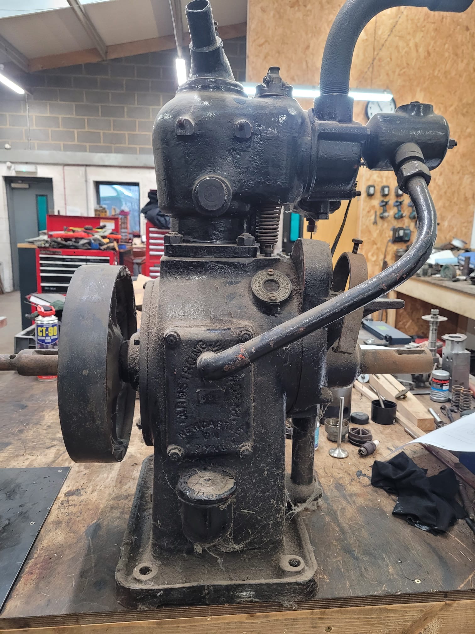
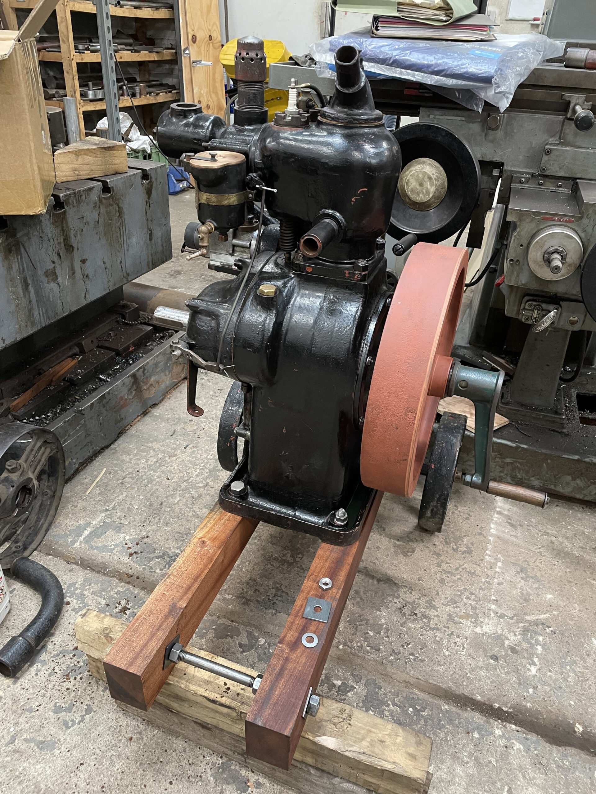
Below: As readers may recall, this engine featured in a post before Christmas. It has now been overhauled and is in running condition, with a trolley even manufactured to make it mobile.
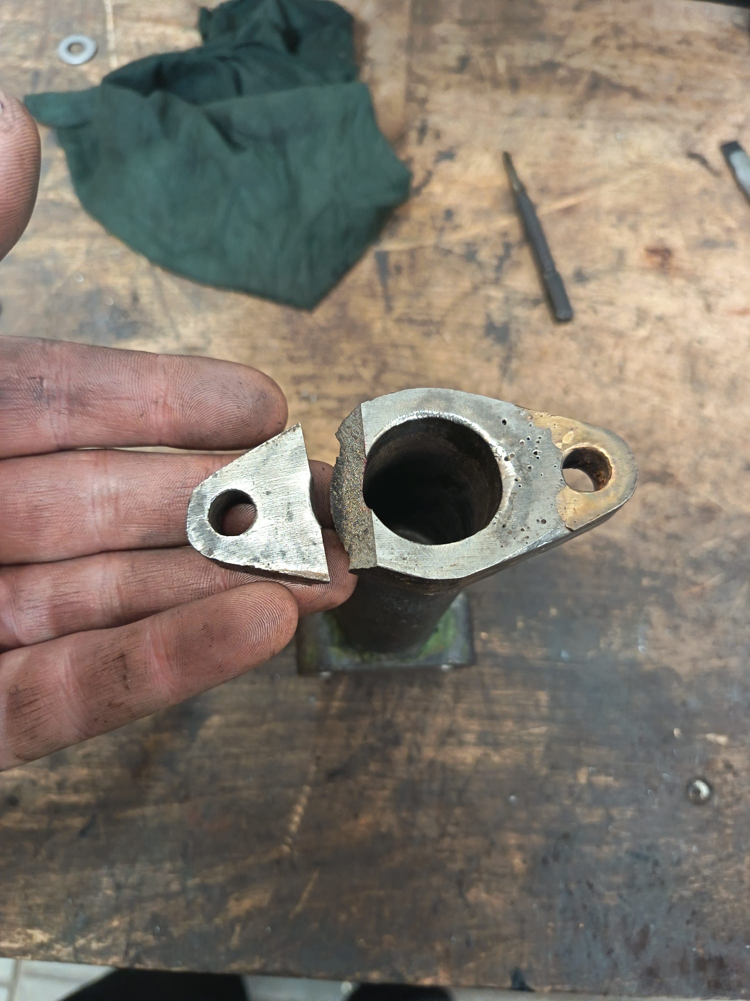
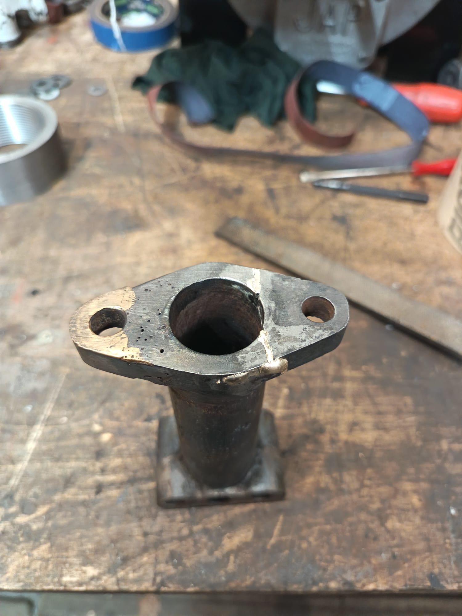
Below: There were numerous repairs to be carried out once the engine was in part-form. Including this flange on the oil pump.
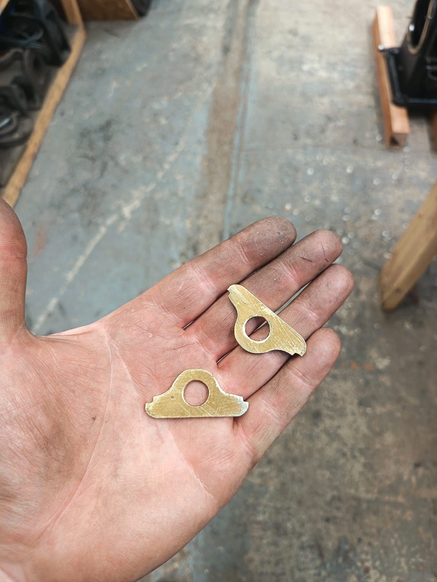
Below: Marking out a new cap for the carburettor.

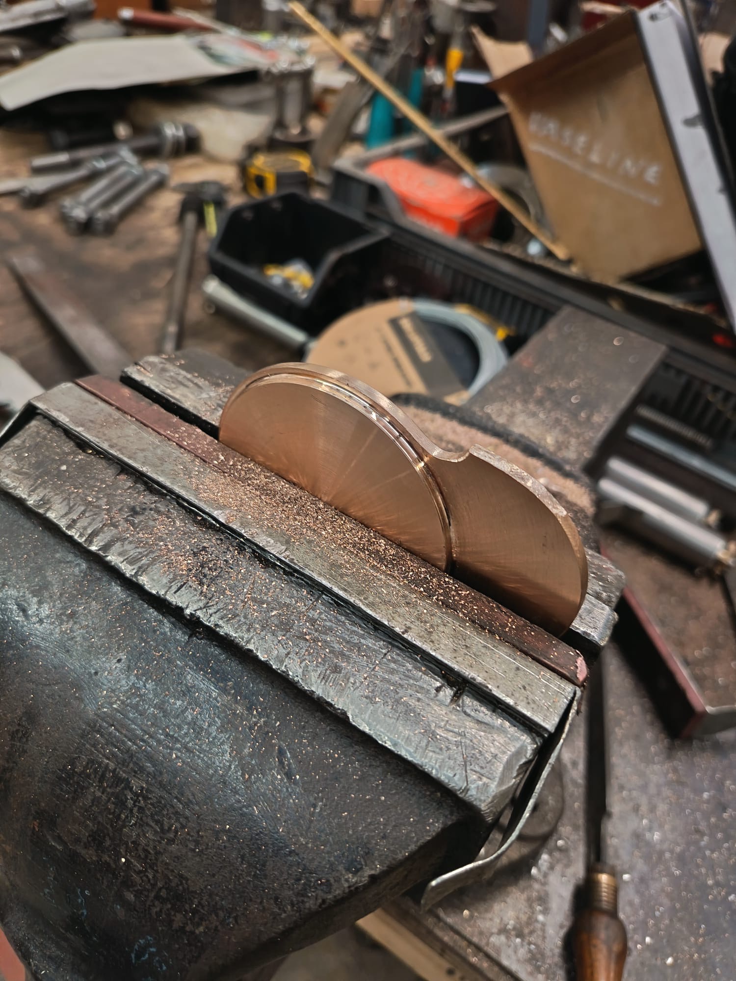
Below: Cutting out the profile of the carburettor cap.
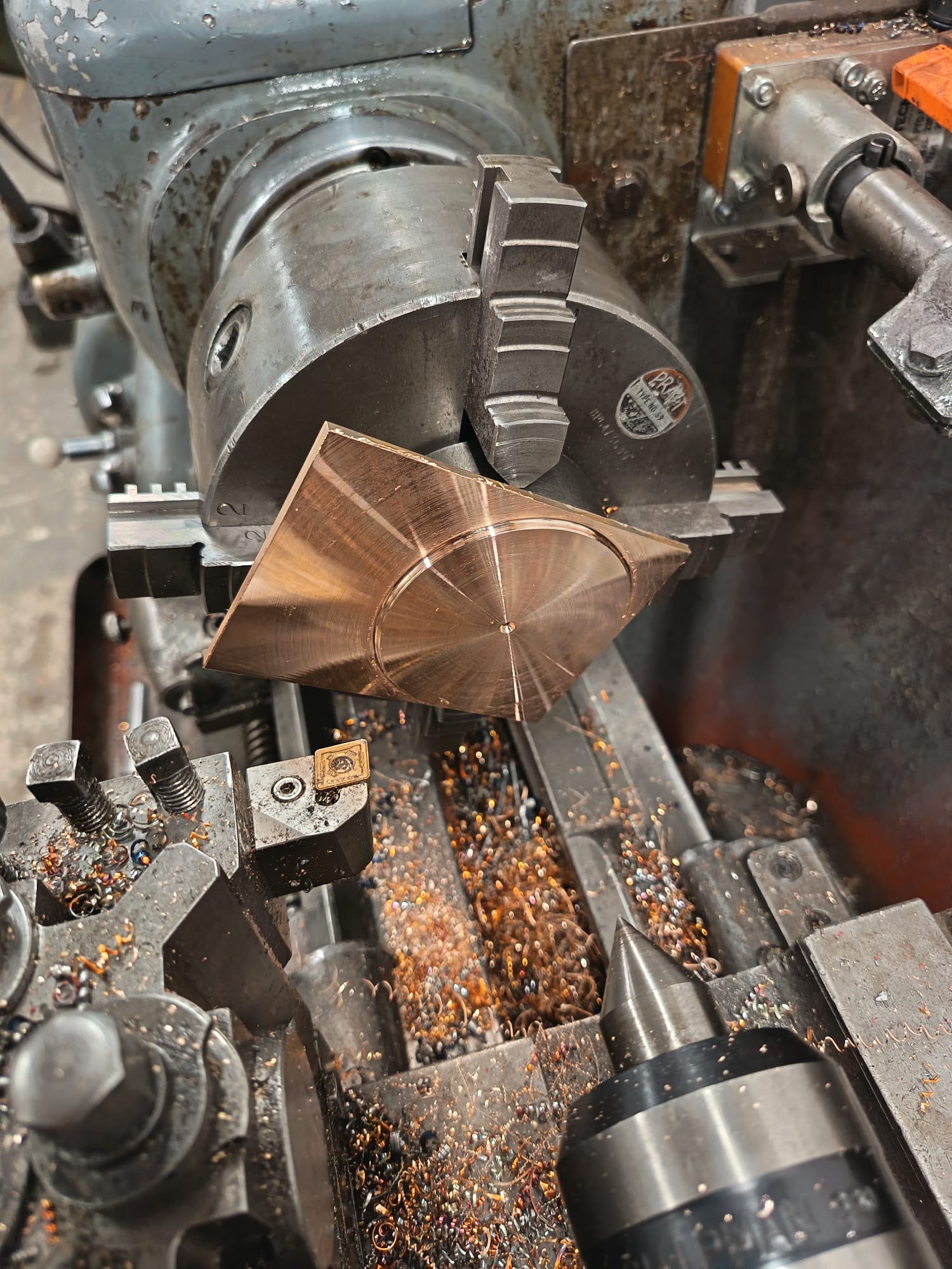
Below: Machining the various profiles for the carburettor cap.
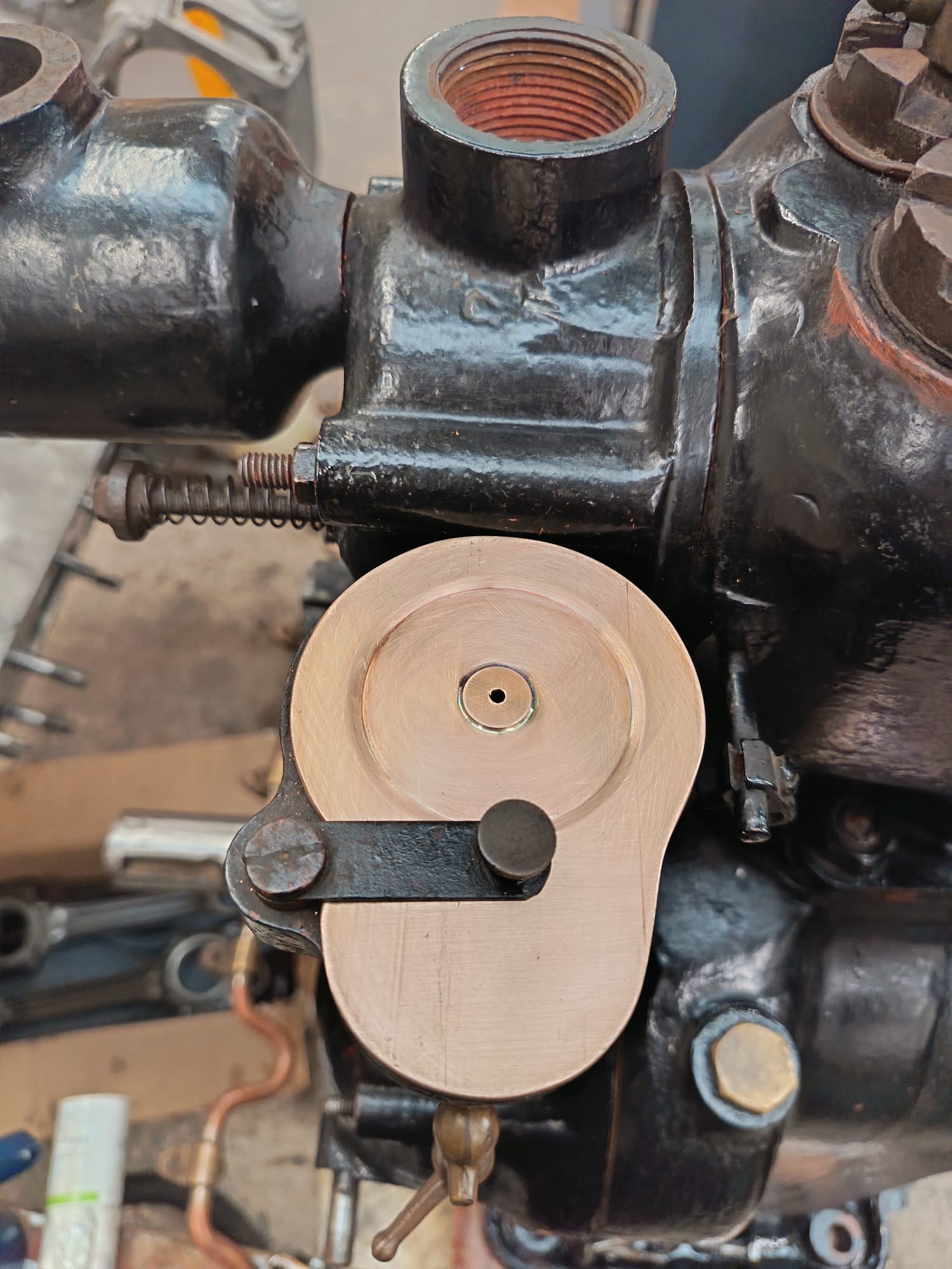
Below: The finished cap, installed on the carburettor.
Below: Shims for the big ends.
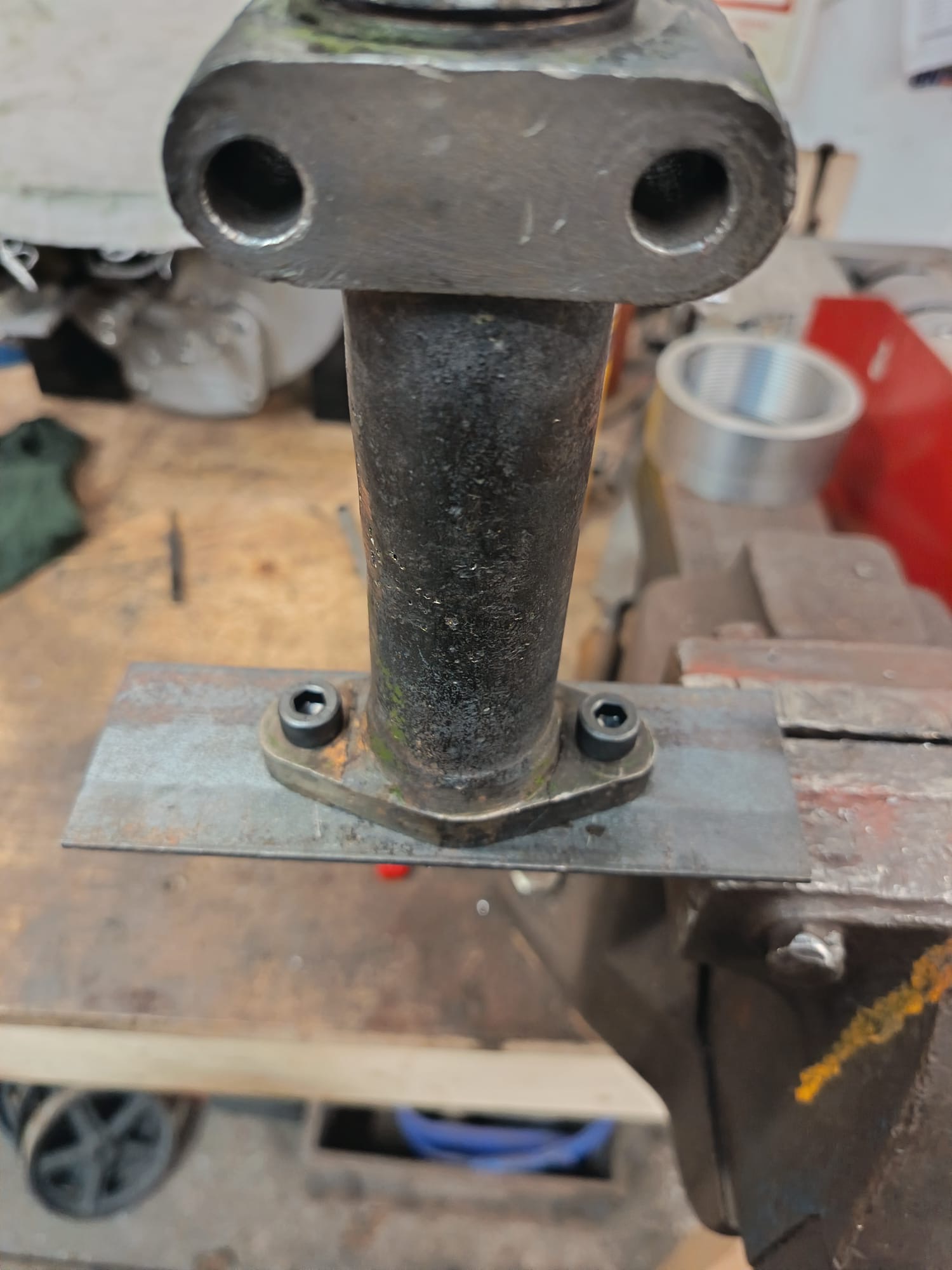
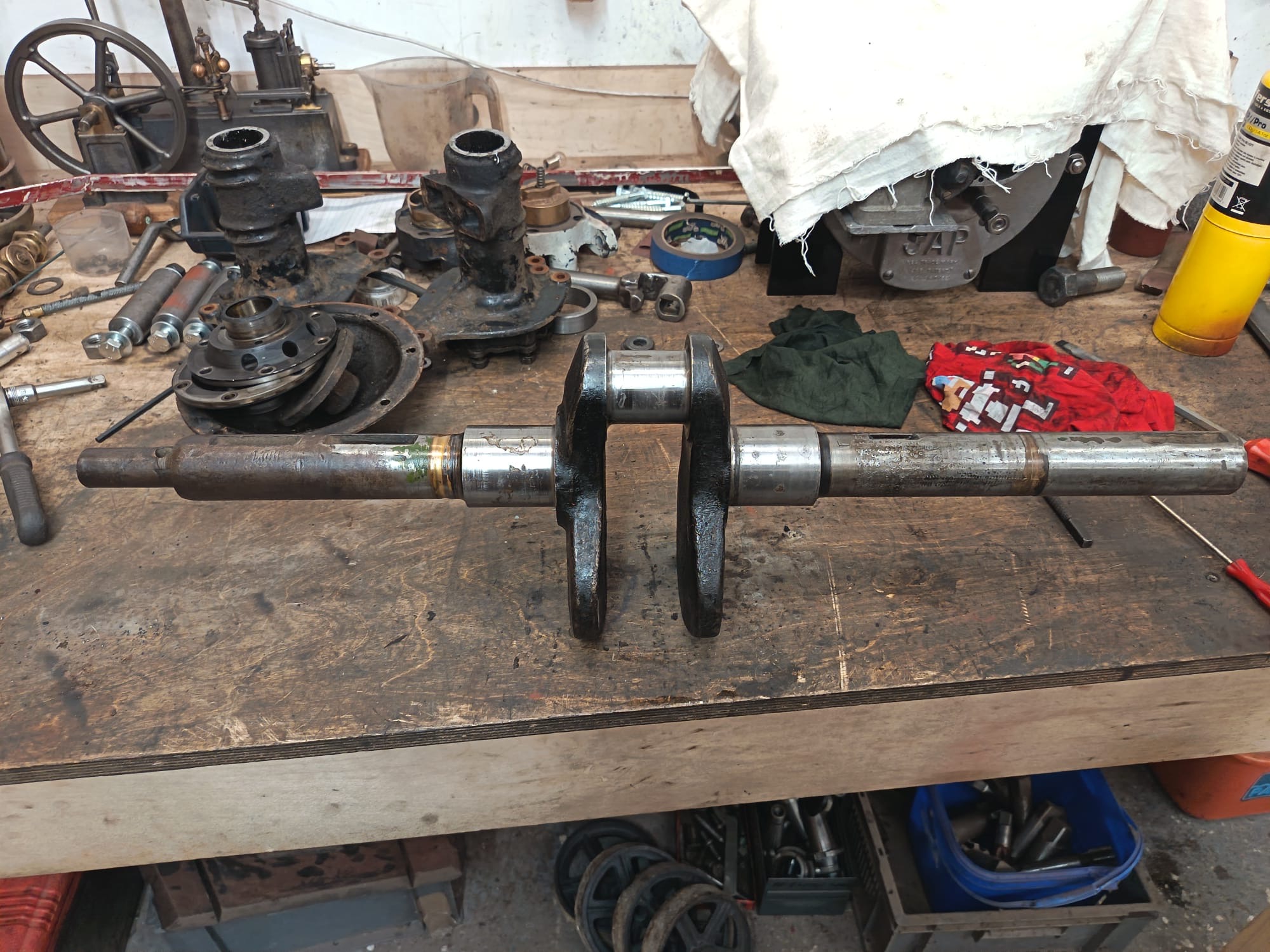
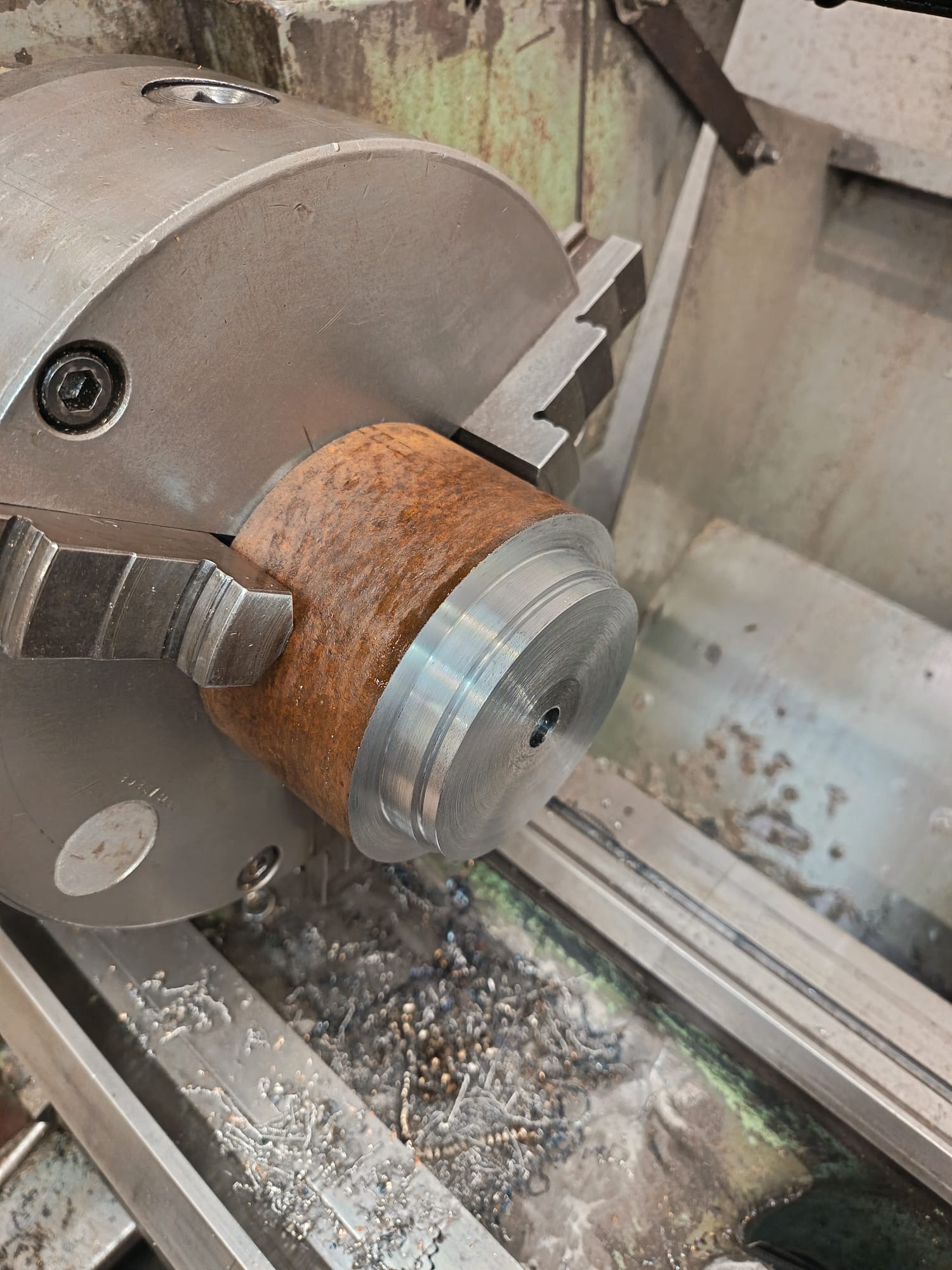
Below: The crankshaft after removal – this required cleaning up and preparing for the new main bearings as well as turning the journal for the flywheel to the correct diameter.
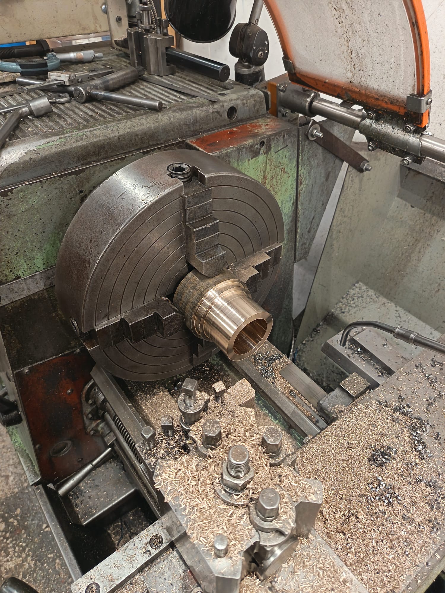
Below: Manufacture of the new main bearings to carry the crankshaft in the engine block casting. Made as one piece and then split for each end required.
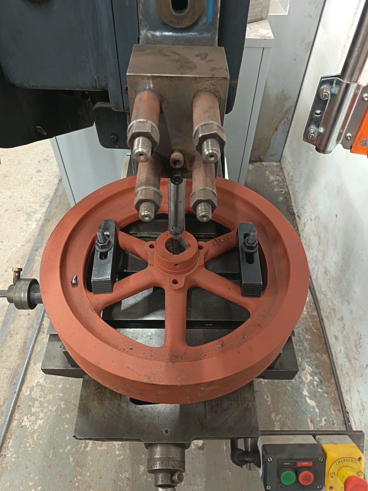
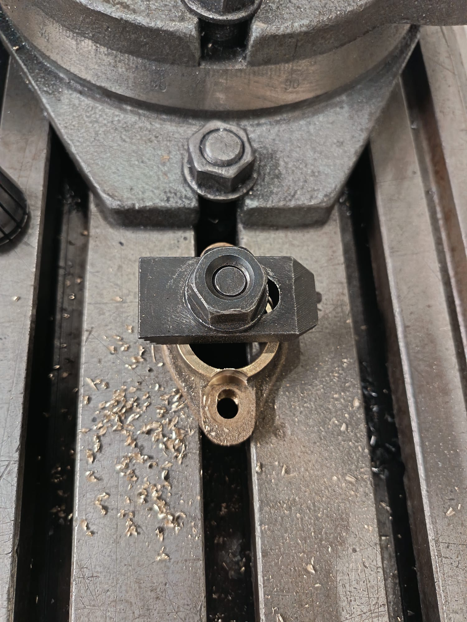
Below: The engine, which is understood to have been used to drive a water pump (or lighting set?) in North Yorkshire in its latter years, did not have a flywheel with it, so a suitable Lister example was adapted to fit. Here the slot for the keyway is being cut.
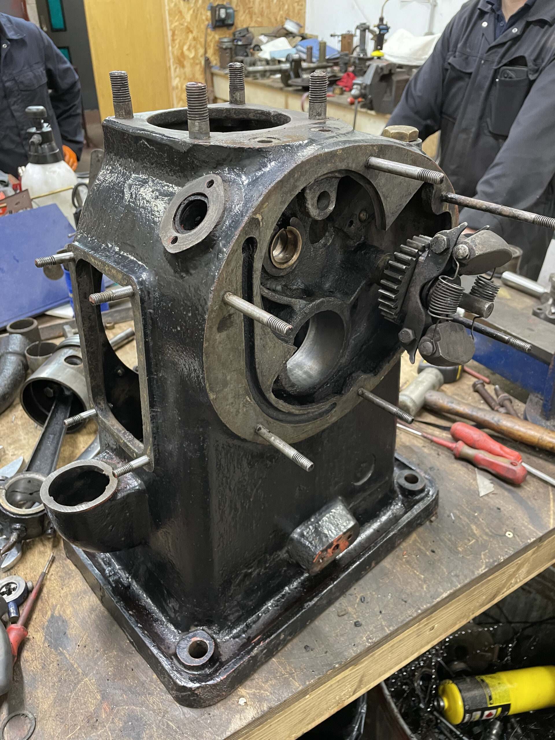
Below: The main engine casting, which includes internal shelves and passages to distribute lubricating oil around the moving parts.

Below: The governor for the engine can be seen here, as can some of the oil shelves. The engine has been made to a high quality, and is positive reflection on the capabilities and reputation of its manufacturer.
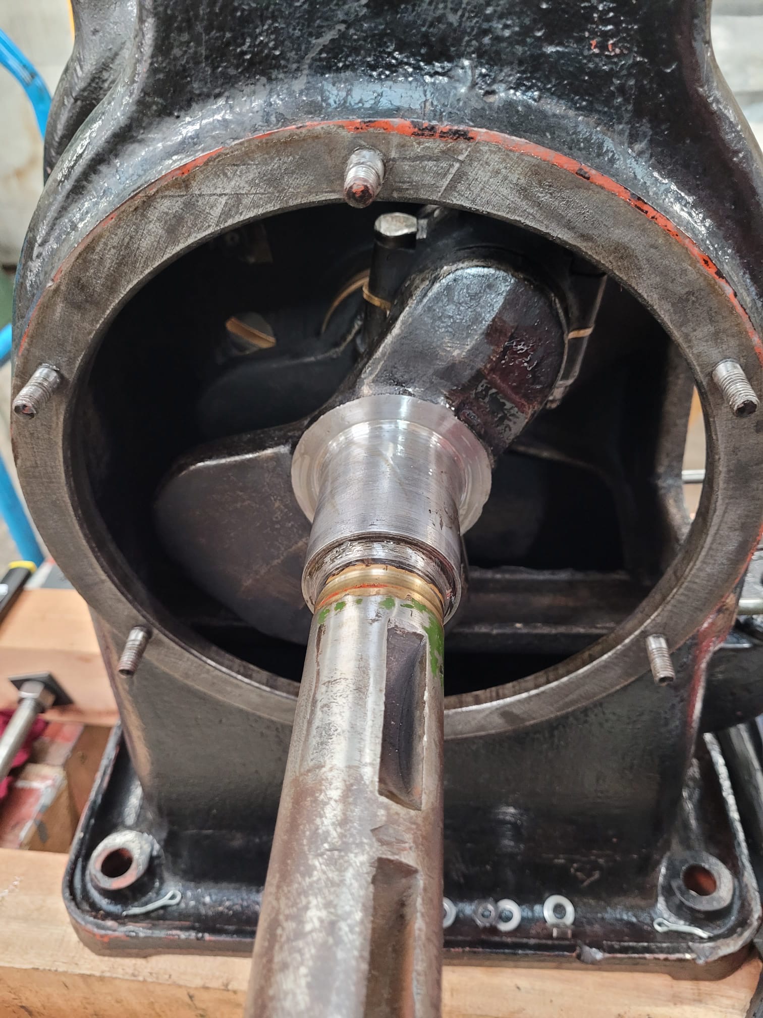
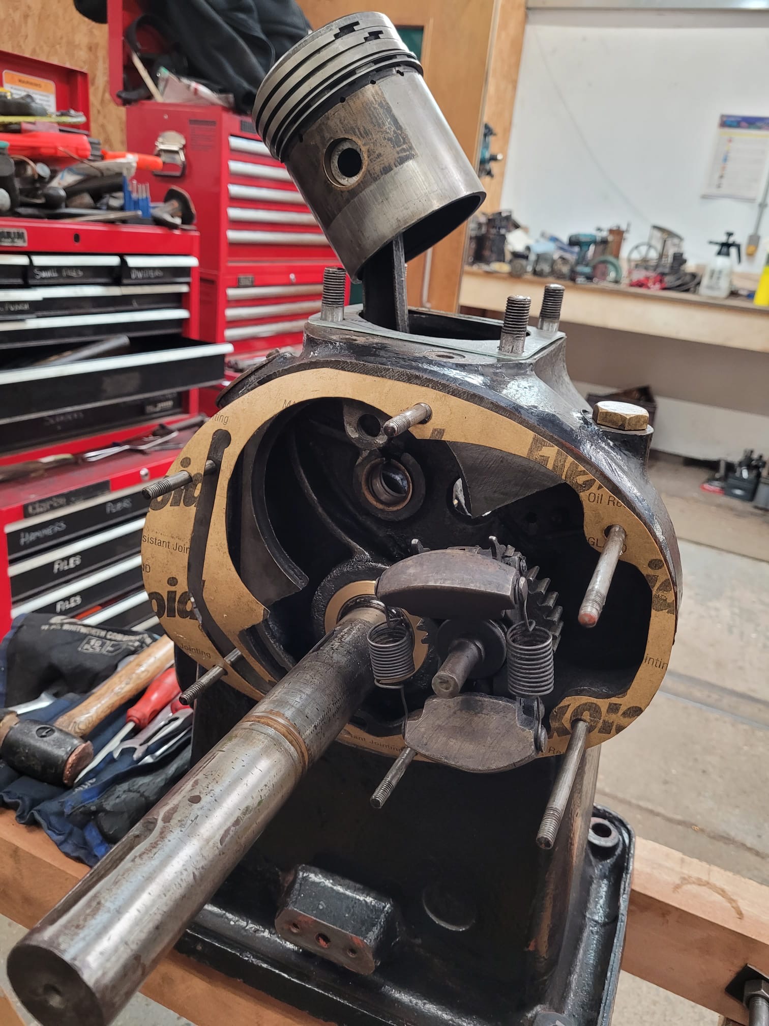
Below: Fitting the crankshaft – the new bearing can be seen in the second photo – it’s the clean bronze coloured item around the crankshaft.
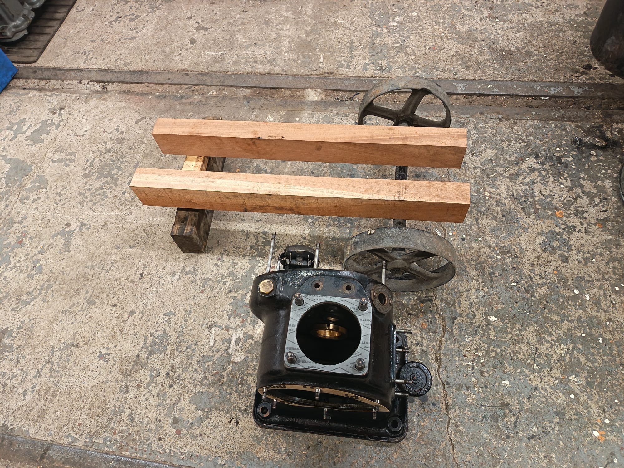
Below: With some suitable wheels and axle recovered from the Colliery, a trolley was manufactured to enable the engine to be more readily moved around.
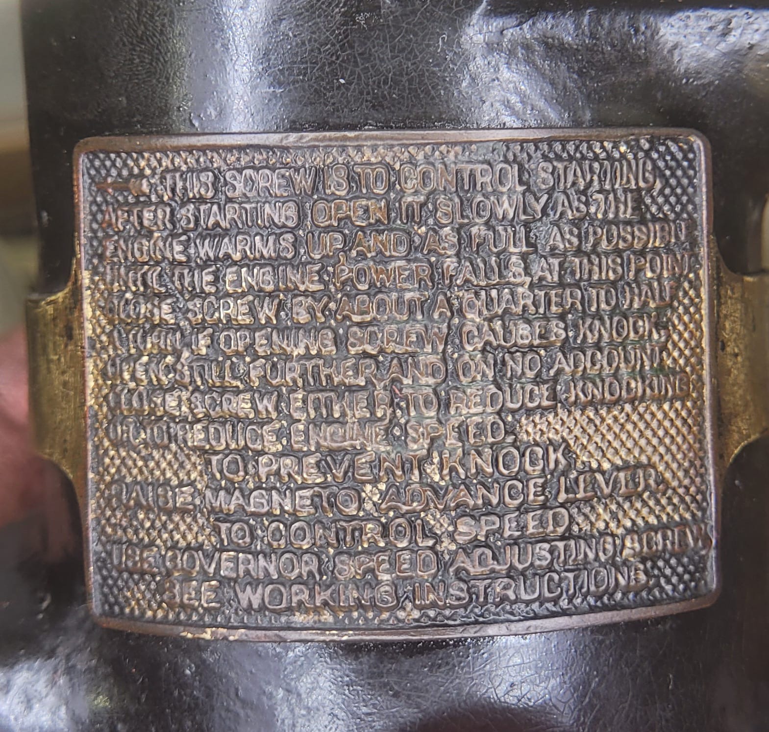
Below: The engine-mounted plate describing the process for starting on petrol and transferring to paraffin operation once the engine is hot.
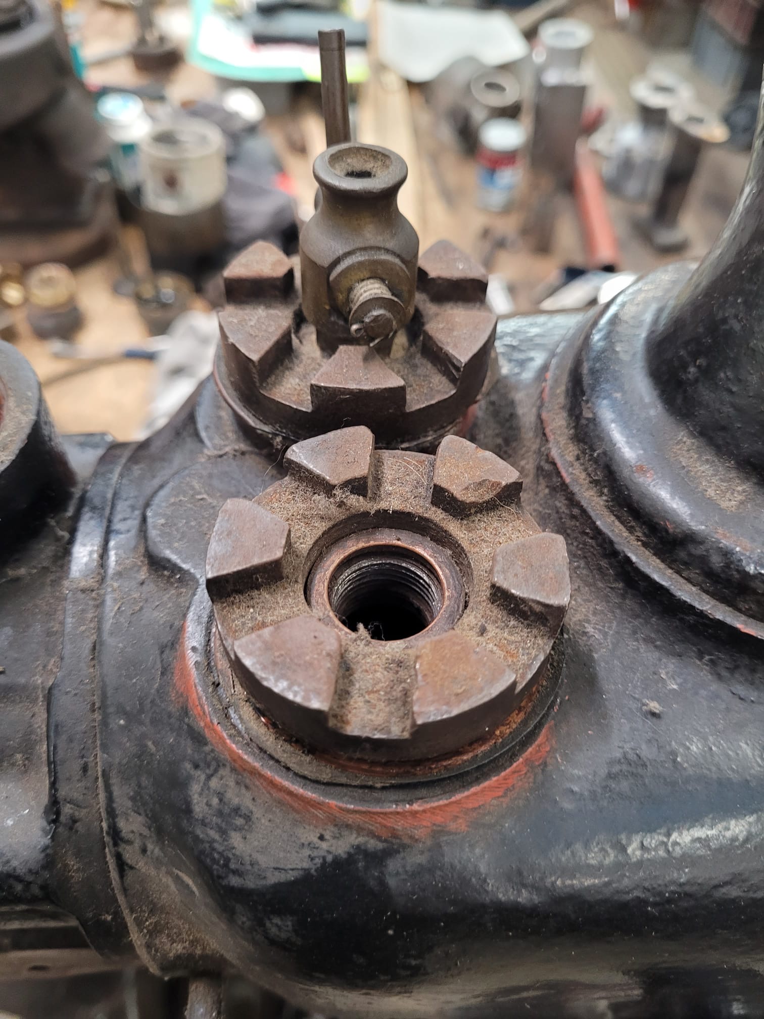
Below: Priming cup (for petrol) and spark plug hole.
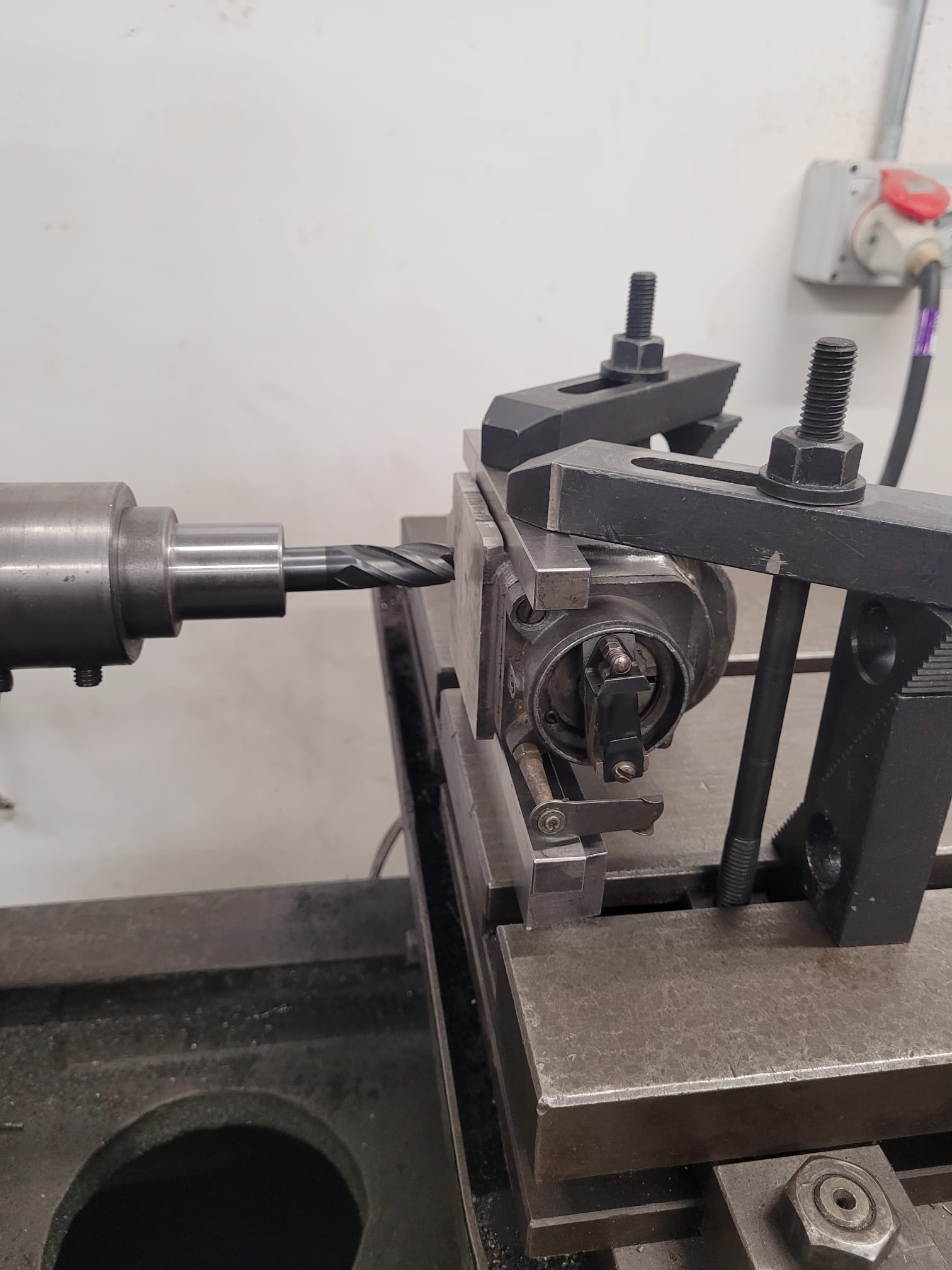
Below: Drilling the mounting holes for the spare magneto found in the stores for this project.
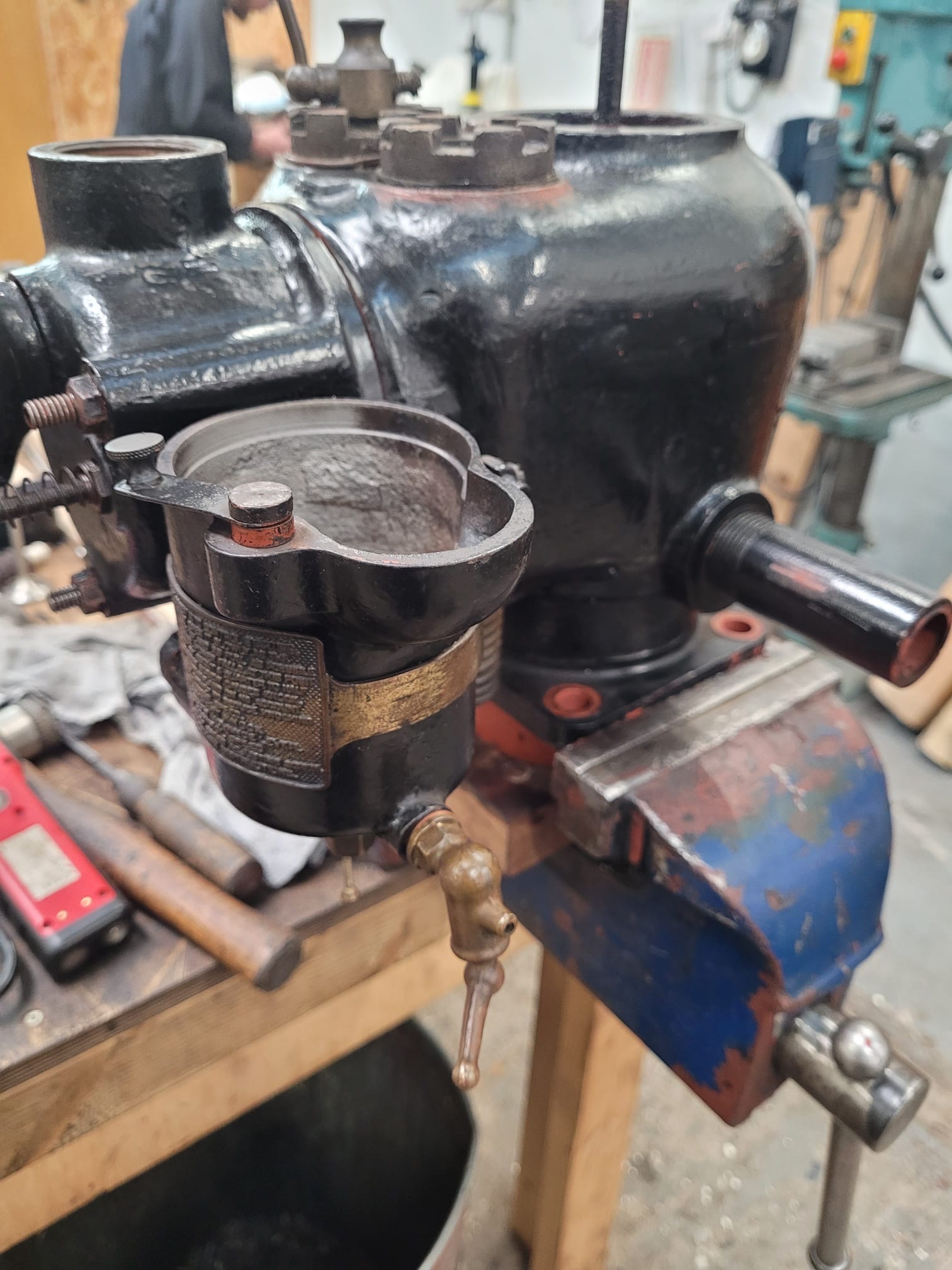
Below: Progress as of mid-January – the engineer is complete and in running condition, the trolley awaits a pair of handles and foot and a suitable water tank is being made (using a redundant air tank from Gateshead 10) for the engine cooling arrangement. A pulley is also needed, to take the belt drive that the engine will now use to impart its energy into whatever it is being asked to drive. The engine was always something of an ornament in the garage, so it is nice to see a locally-built and fairly rare industrial item returned to working order and in such a way as to allow it to be better understood and used for engagement purposes at the museum. The engine will be partially re-painted, but it will be kept in it’s working guise, as whilst the black paintwork may be relatively recent, it already has a patina that is quite authentic for the garage setting where it will reside.
Armstrong Whitworth Car
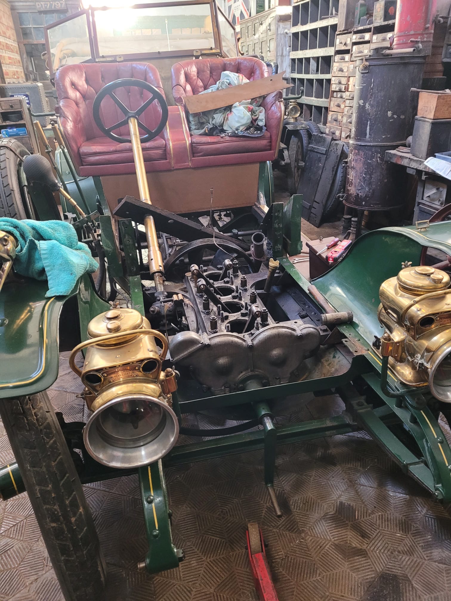
Below: The winter programme of work on the AW Car has been making good progress, with its volunteer team usually carrying out one day per week on it, and the workshop staff filling in when they have time available. As has been reported previously, the cylinders have been removed and it was planned to leave the main block in place, along with the gearbox. However, as work progressed it made more sense to remove the gearbox at this stage as well (as a machine shop overhaul) and then the whole engine. This necessitated more dismantling, but also released the wooden bulkhead, which one of the volunteers will be restoring to remove fading and water damage.
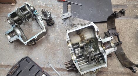
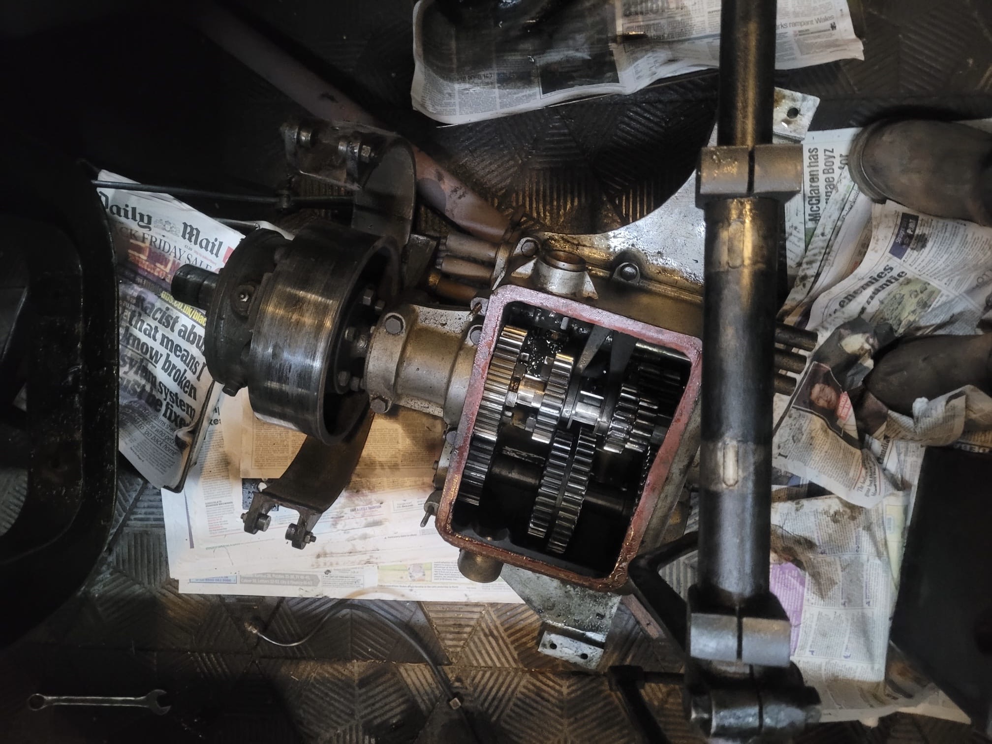
Below: The gearbox, after removal. There were a few issues that had manifest themselves in use, and a problem with the way in which reverse gear was engaged but would make a commotion when reversing when there was no load upon it.
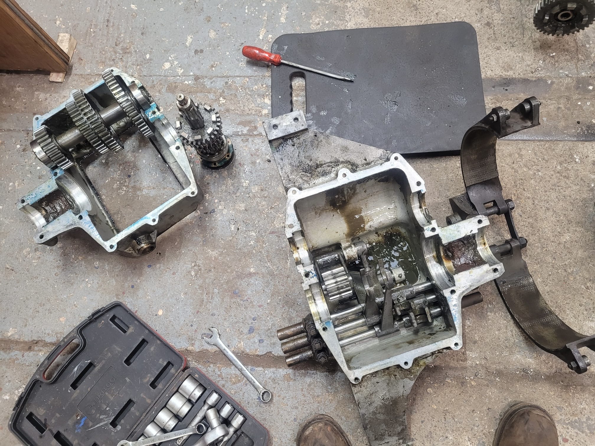
Below: One of the bearing housings on the gearbox casing had insulation tape, a plastic cap and jubilee clip fitted, to prevent oil egress – a more professional and enduring solution has been made by boring holes circular and the purchase of new bearings (available off the shelf!).

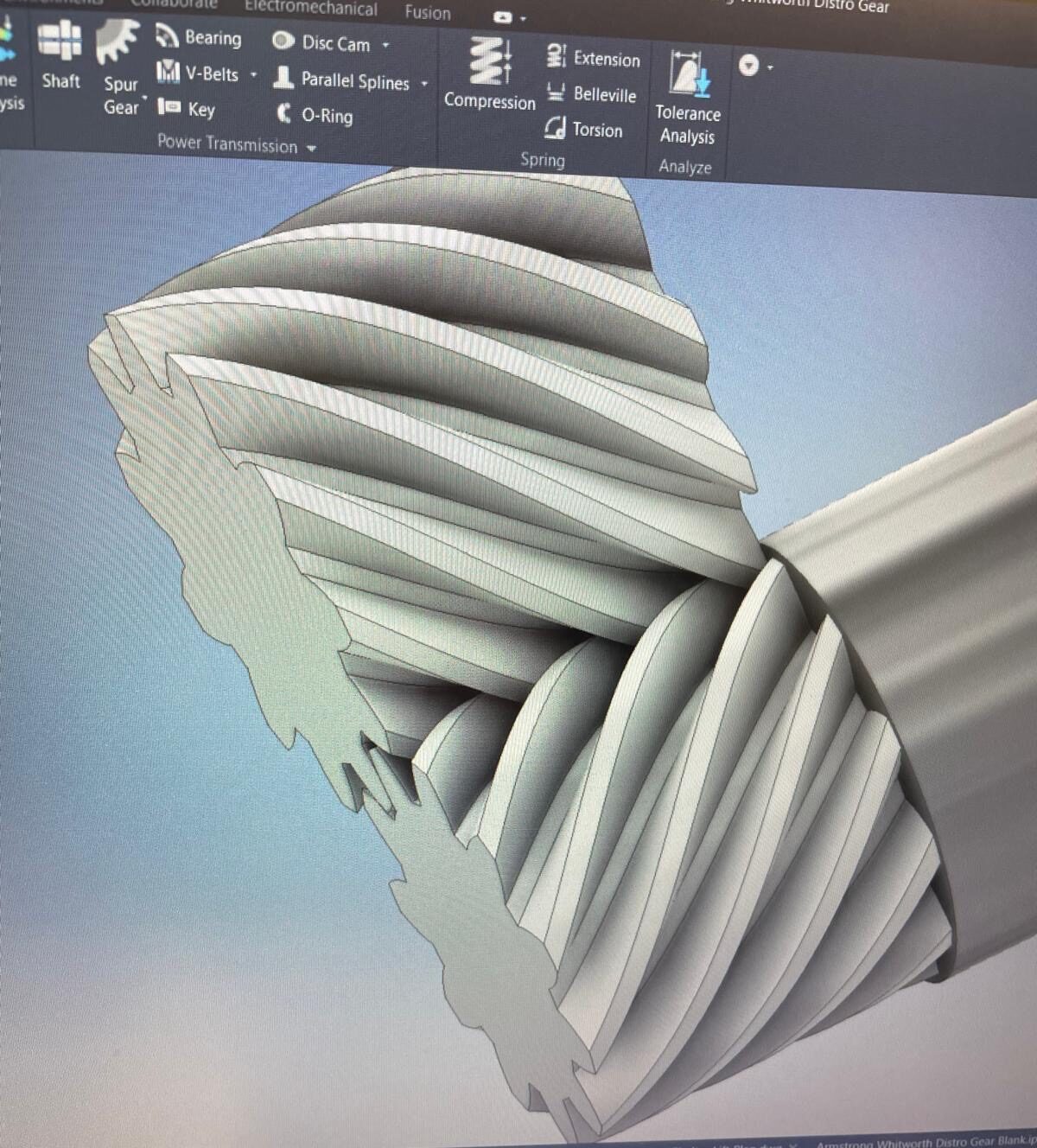
Below: One feature of the car that is missing is the mechanical drive to the distributor. There was evidence of it, but the drive itself was absent. Chris has drawn the arrangement up, to enable 3D prints to be made. This is all quite Escher-like in appearance, especially when rotated 90 degrees – but as will be seen further on, it workers rather elegantly! The gears are a paired helical spur gear with parallel teeth. They were drawn as a pair like this, with the 45 degree helix enabling (it was hoped – rightly as it turned out) that they could be rotated 90 degrees and still mesh correctly.
Below; The 3D printed gears were trial fitted to the engine…
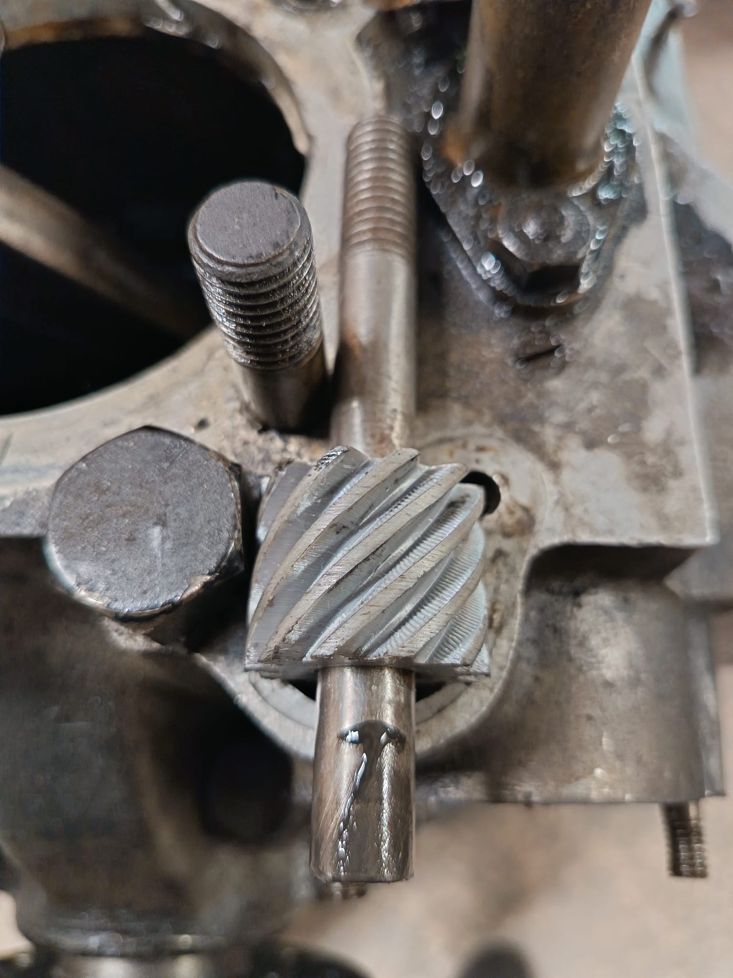
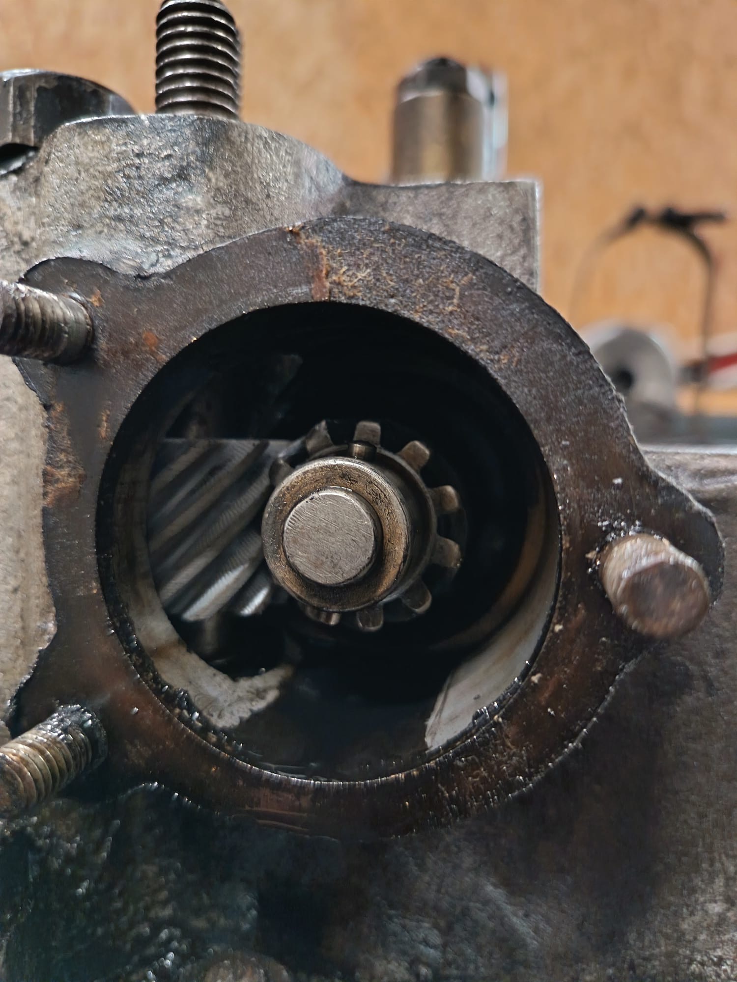
Below: The link below shows the cause of much elation! The gears will now be sourced (in metal!), to enable this feature of the car to be restored.
Below: The new gears appeared in the post and one will be used in the distributor drive, the other held as a spare.

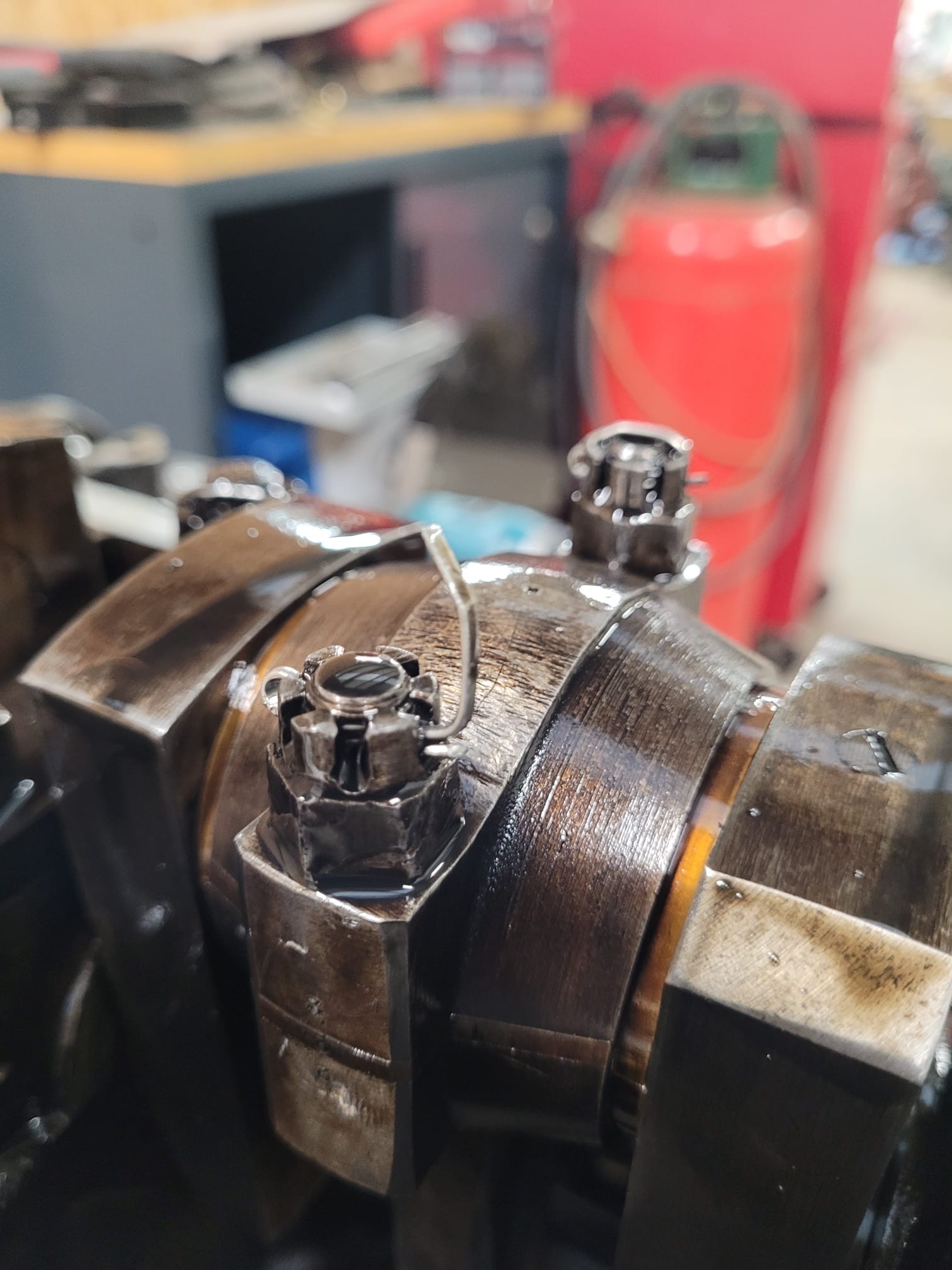
Below: With the above work explored and progressed, the engine was inverted and the sump removed. Physical examination revealed some excess play where the connecting rods and crankshaft interact.

Below: The split pin leg may have been causing the fouling of the spark plug on this cylinder – something that is easy to remedy upon reassembly.
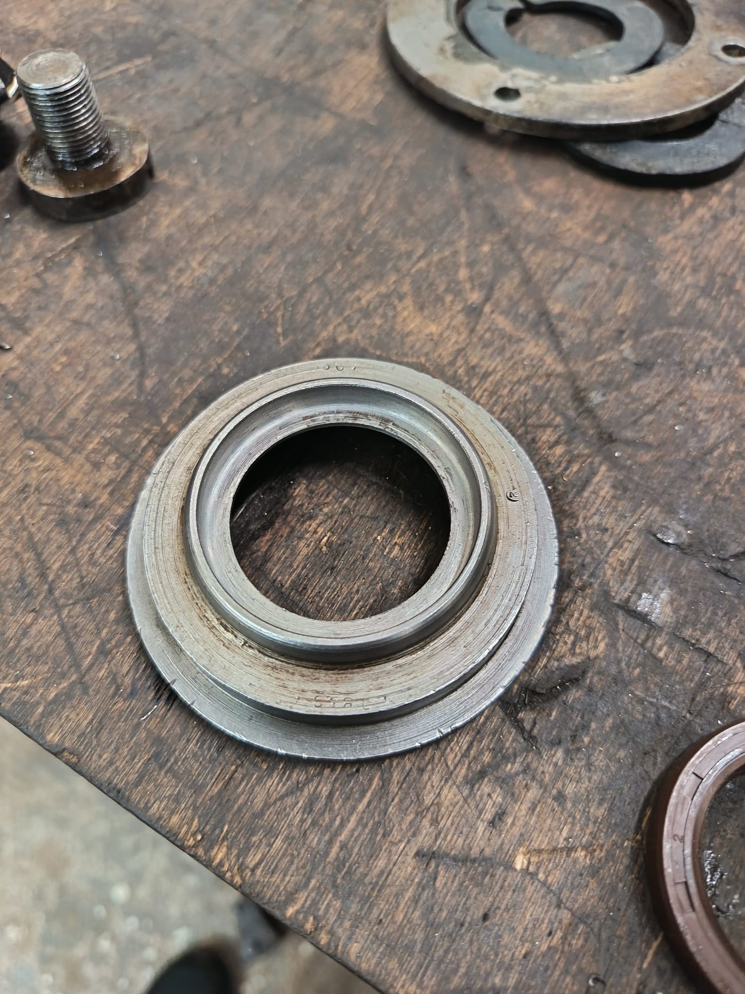
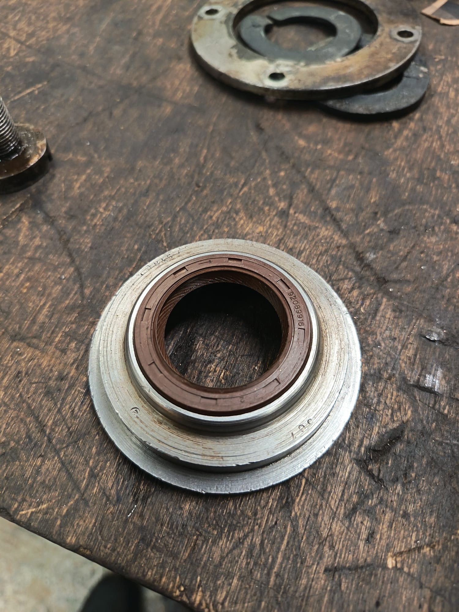
Below: The gearbox output shaft seal housing has been modified in order to take a modern oil seal in place of the felt one originally fitted (second photograph).
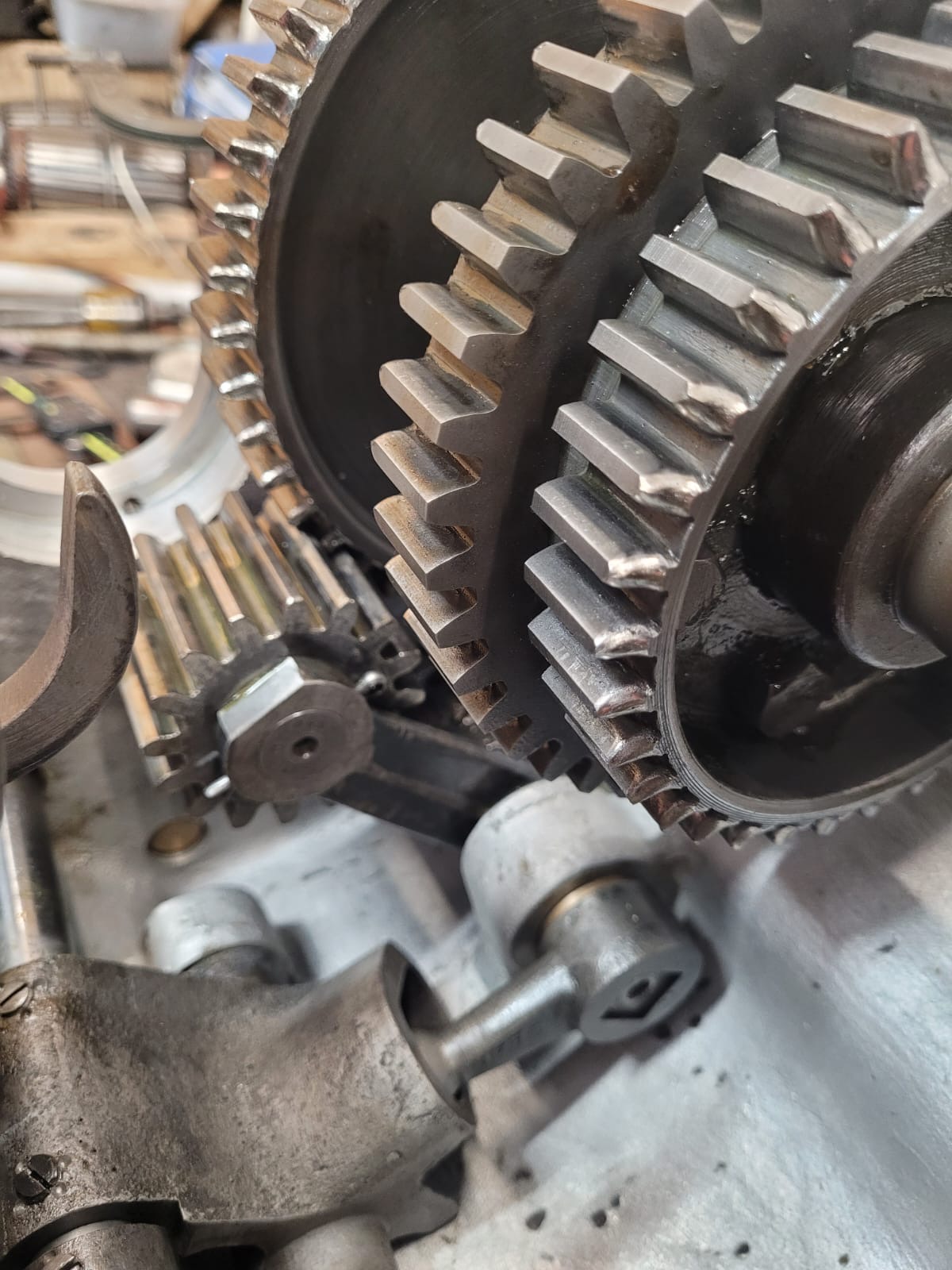
Below: The reverse gear – the small pinion to the left of this view – has been overhauled in order to positively engage and retain the gear in mesh once reverse has been selected. Excessive play was causing the gear to drop clear of its ideal alignment, resulting in a fairly unpleasant sound when coasting in reverse. With this work done, the gearbox has been reassembled in order for it to be reinstalled in the car shortly.
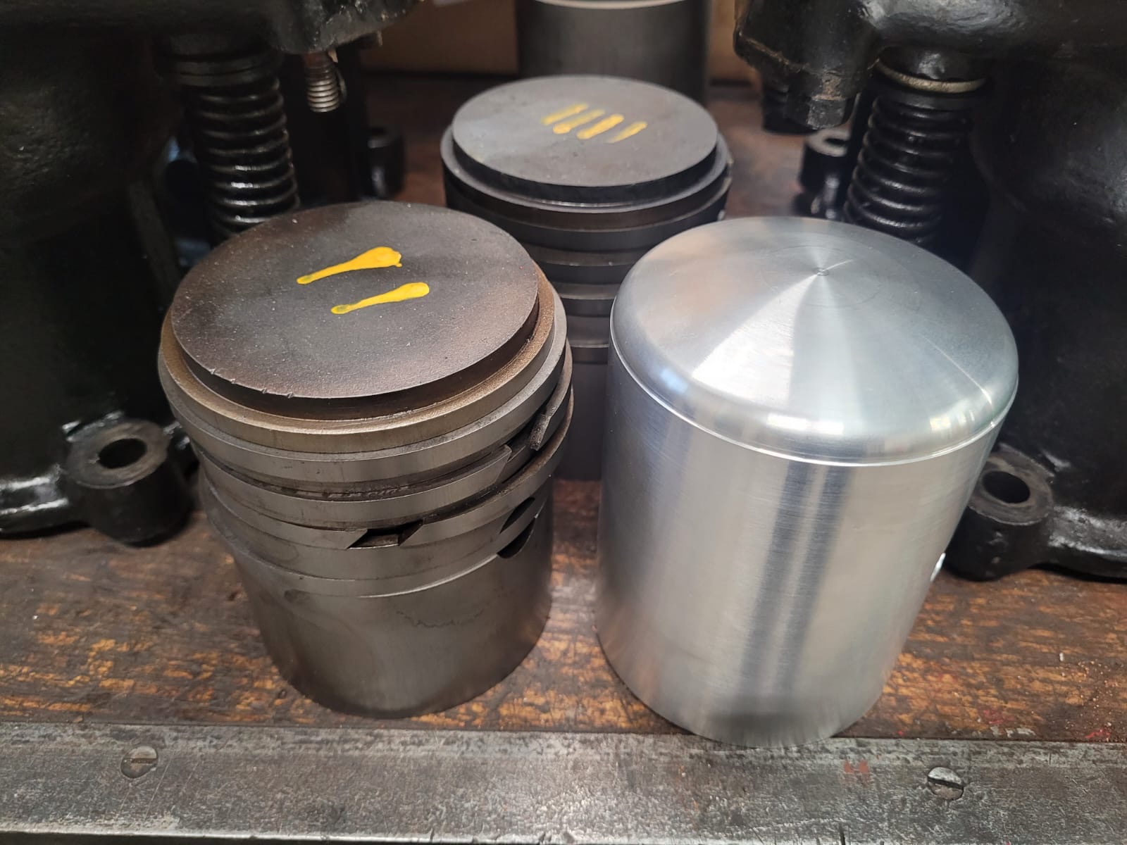
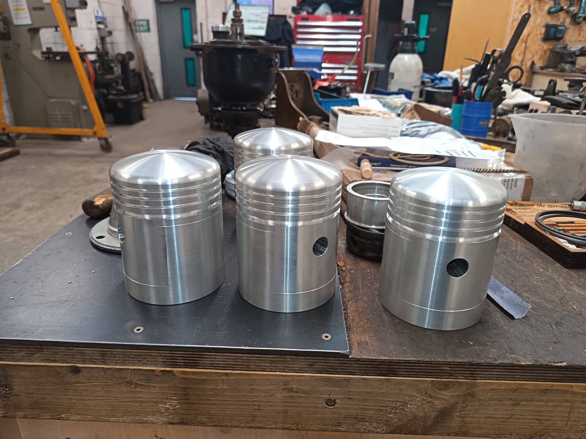
Below: The batch of new pistons has been received (seen on the right here), and await final machining and the grooves cutting in for the rings. They have been made oversize, to give a machining allowance now, and to enable the spares to accommodate any future work that entails re-boring the cylinders to a larger diameter.
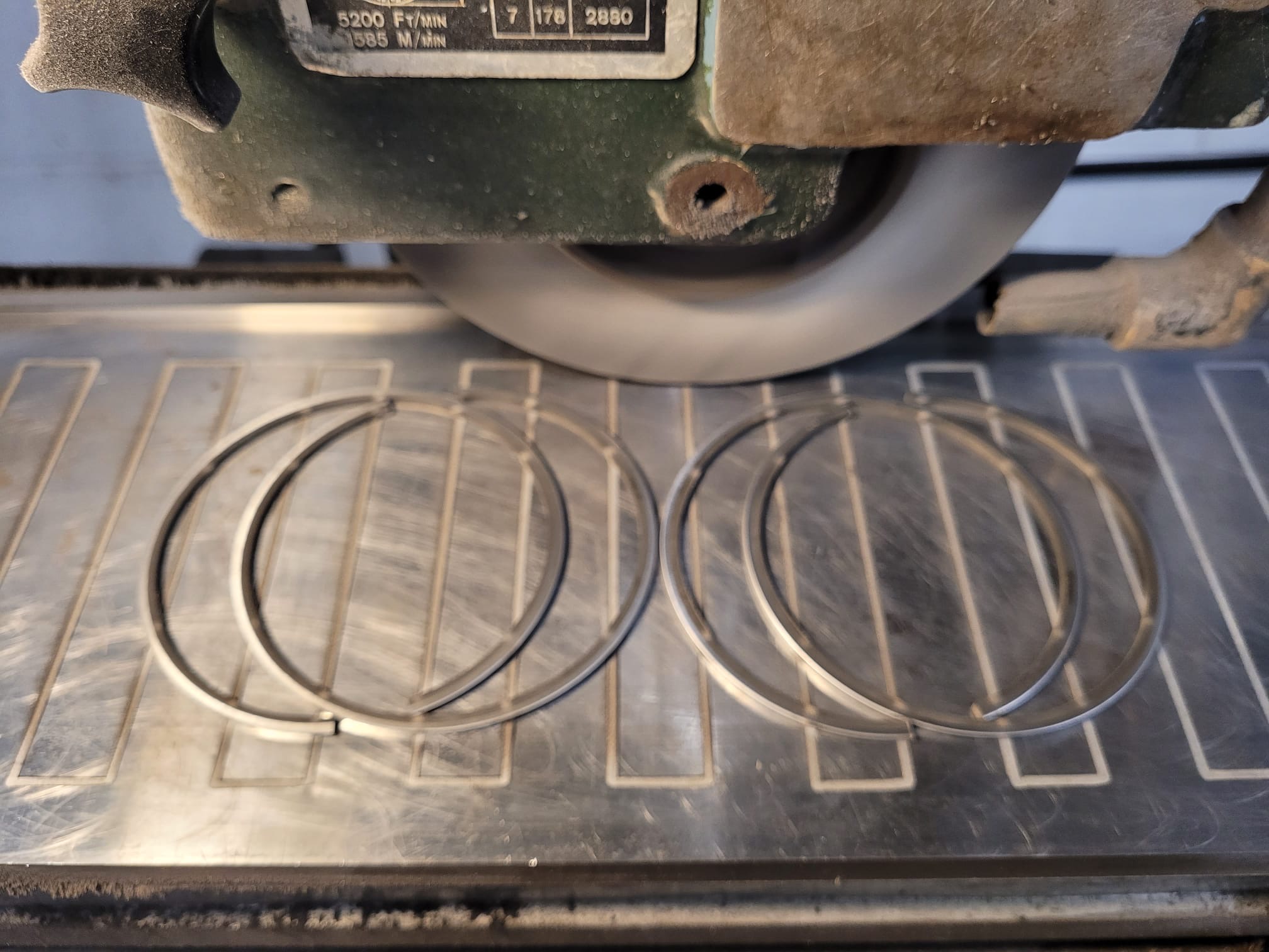
Below: Commercial diesel piston rings are being used for the Armstrong – seen here on the surface grinder being prepared for installation on the pistons.
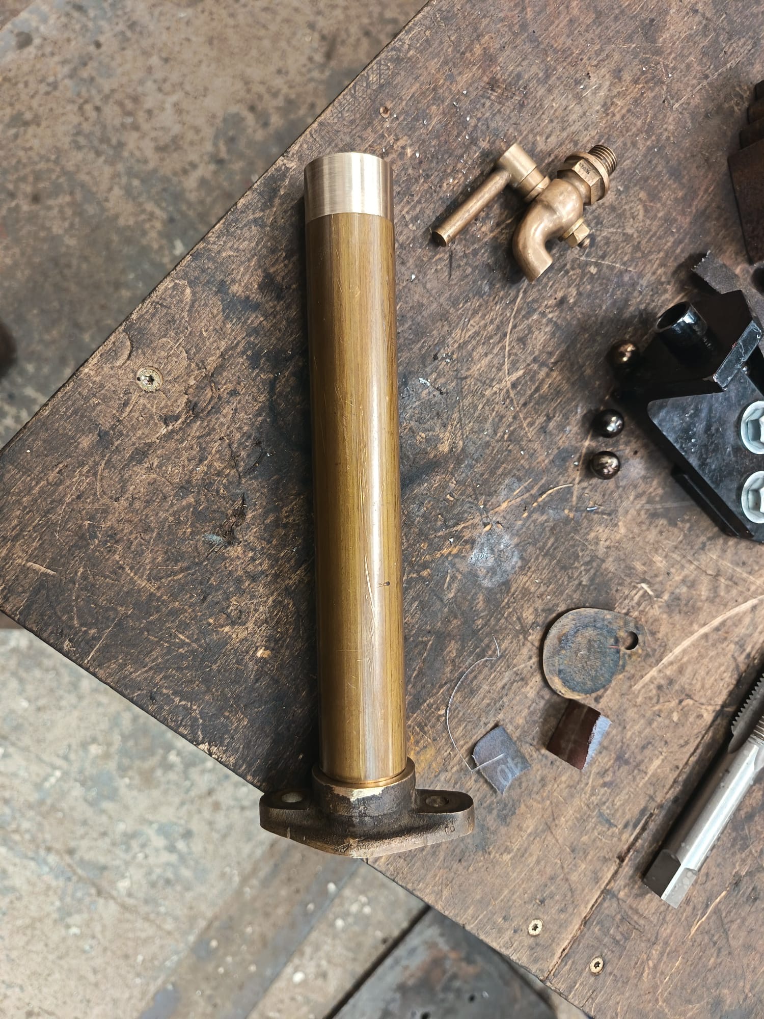
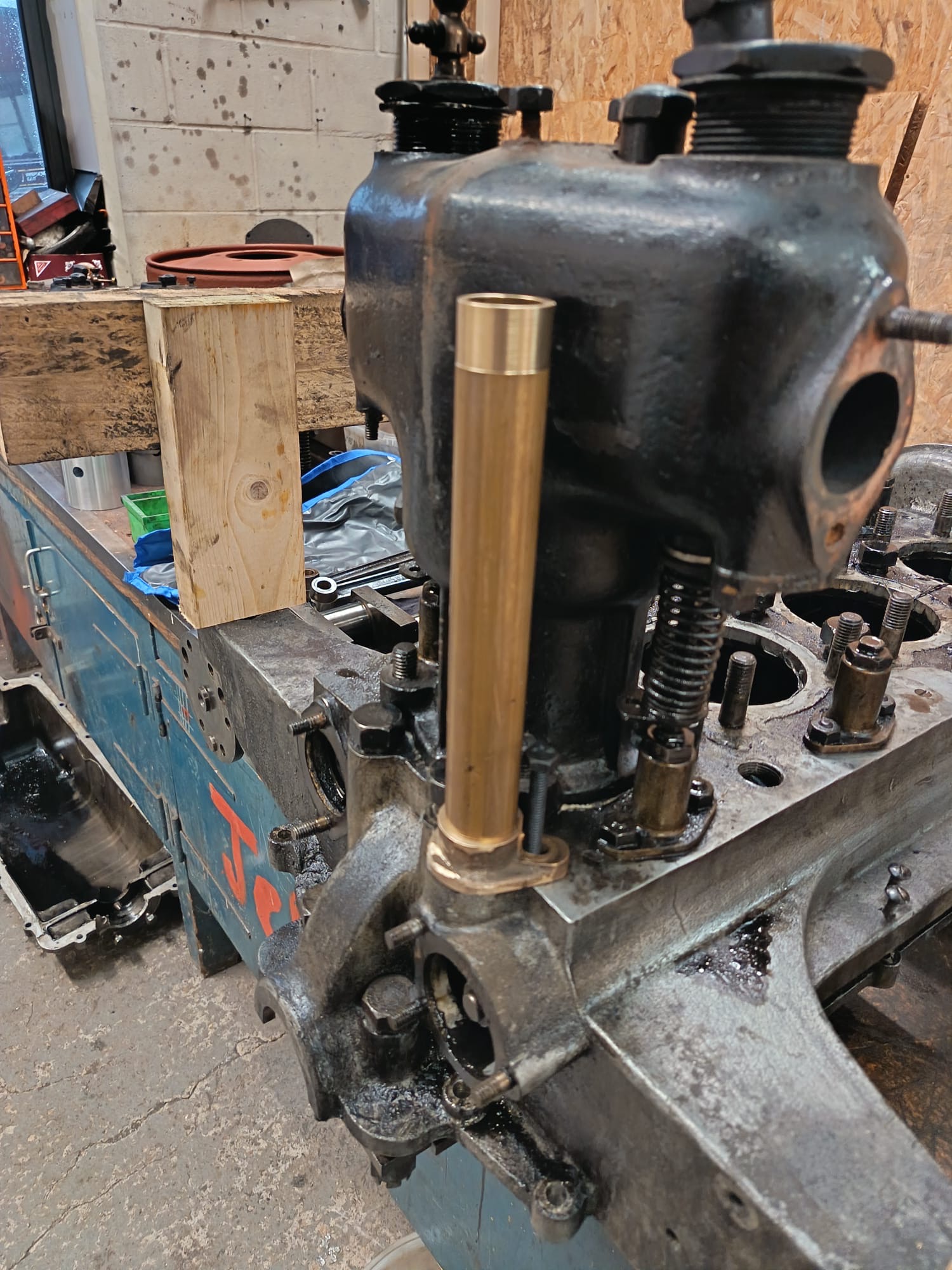
Below: This next item is the new distributor tower, which contains the drive shaft from the engine to the distributor mounted on top of it. A revised arrangement had been made, and this component was lost to the car, but study of the remaining components as well as photographs has enabled the replica item to be manufactured, with the aim of restoring this feature to operation.
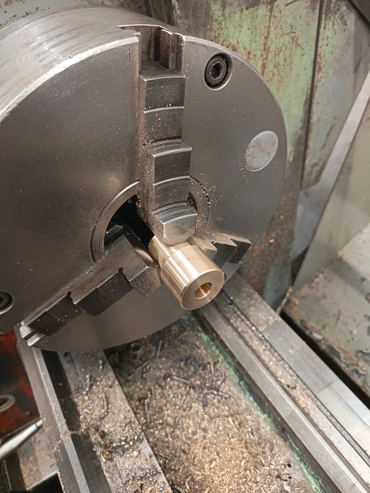
Below: Manufacturing a new flange to mount the tower on the engine and distributor on the tower. Final height to be determined once the engine has been reassembled.
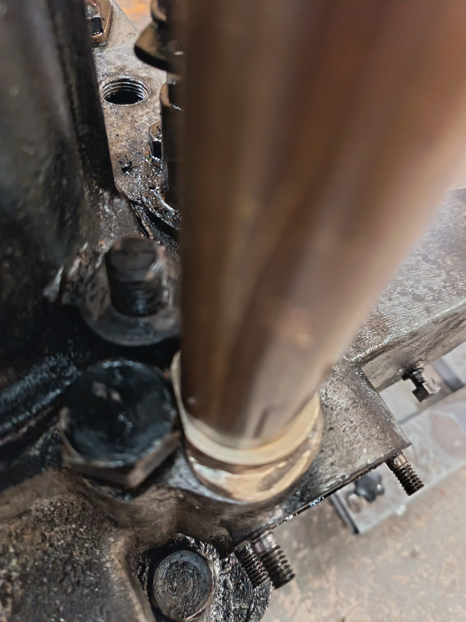
Below: Trial assembly of the tower, on top of the crankcase and with one of the cylinders fitted to check clearances.
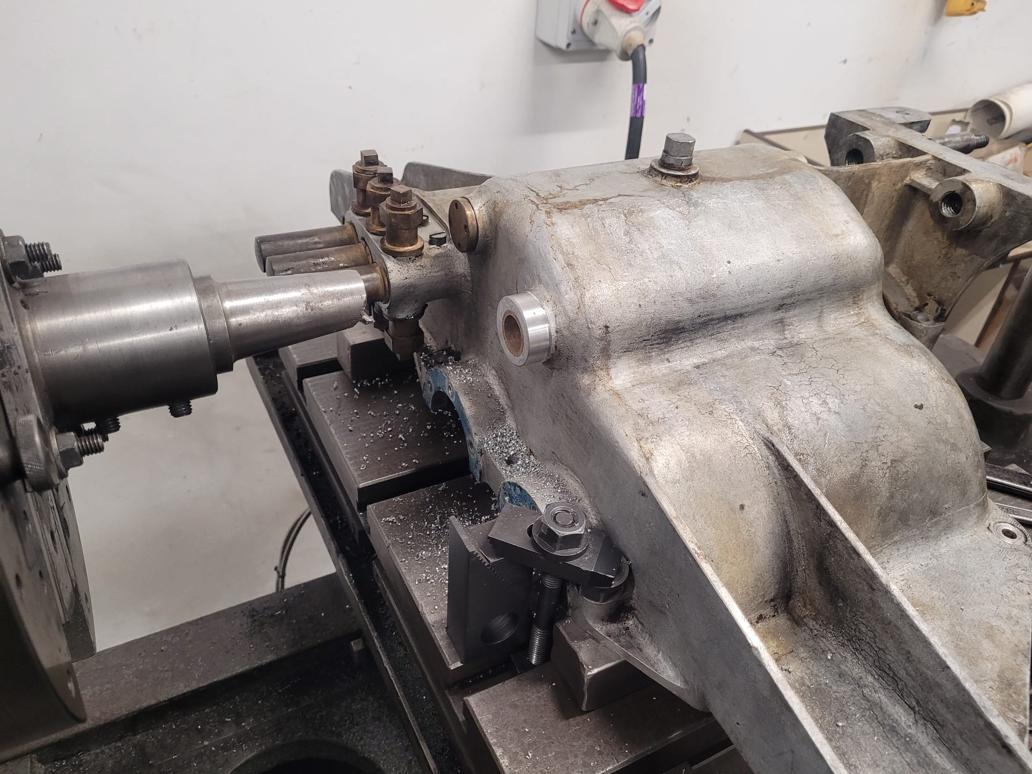
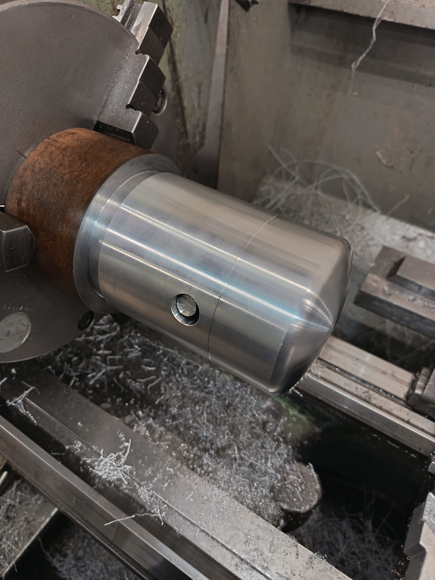
Below: Next it was time to machine the new pistons. A mandrel was made to hold these, with a drawbar through the headstock to pull the piston up against the mandrel for turning.
Below: This view shows a raw piston, with the drawbar in place and pulling up on the wrist pin. As will be recalled, these pistons were supplied a little over size (deliberately).
Below: Machining the piston ring compression grooves, plus an additional one to take an oil control ring – something not previously fitted to the engine. The original pistons will be added to the Garage display so the design/knowledge for these will not be lost.
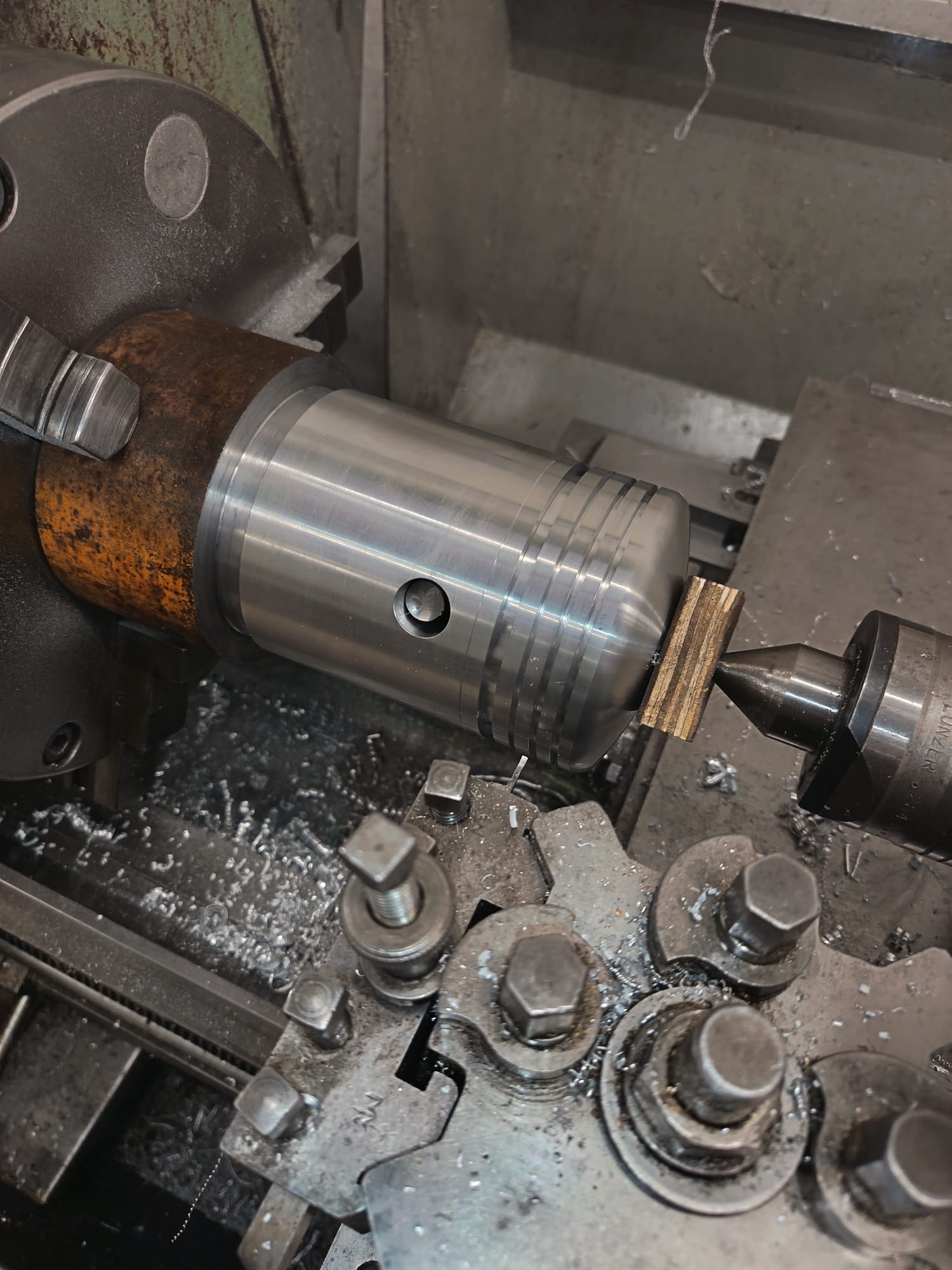
Below: Piston mandrel was off-set slightly for final turning, to create a very slight egg-shape to the piston to allow for expansion when hot (as the internal design is not equal, all around – for example where the wrist pins are located).
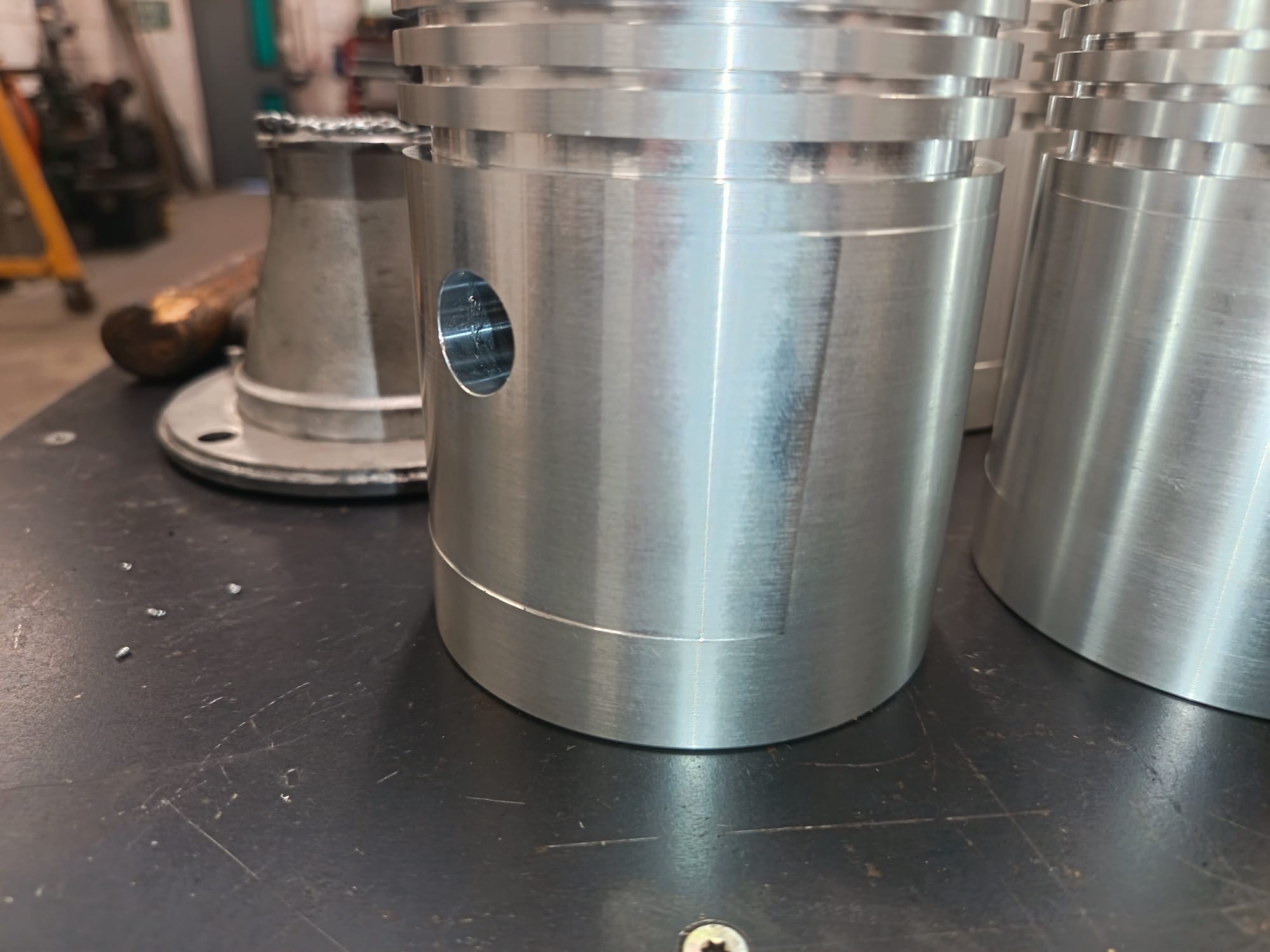
Below: Pistons complete…
Below: The cam followers were heavily pitted, so new ones have been made and are seen here on the surface grinder being ground to their final thickness.
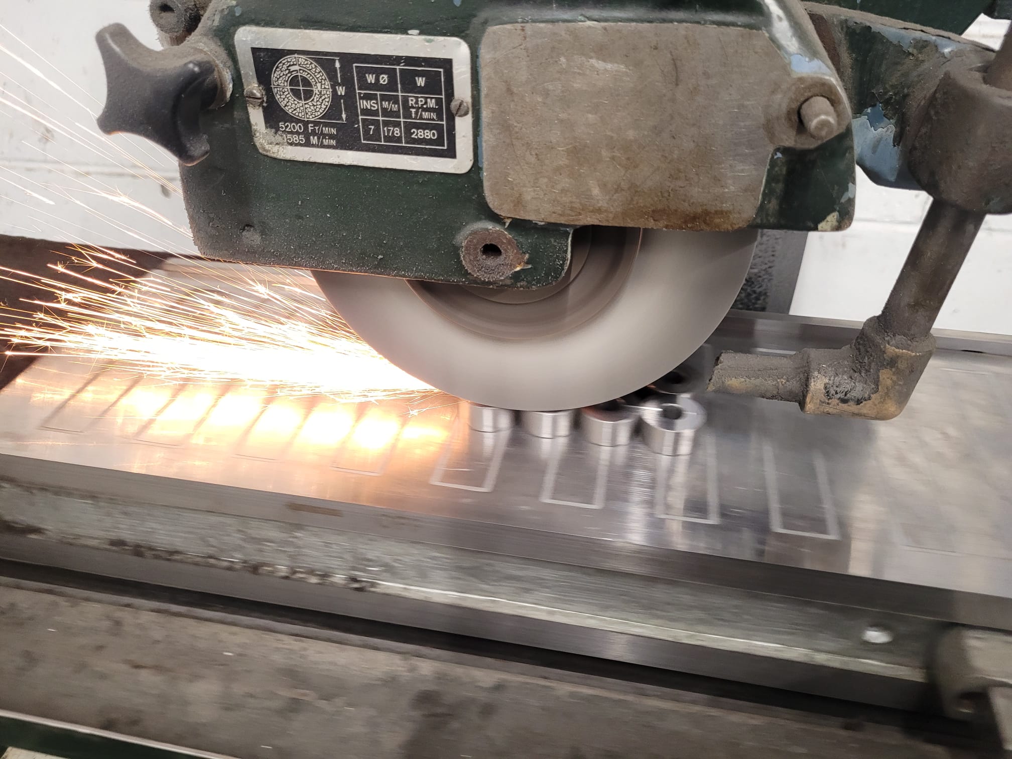
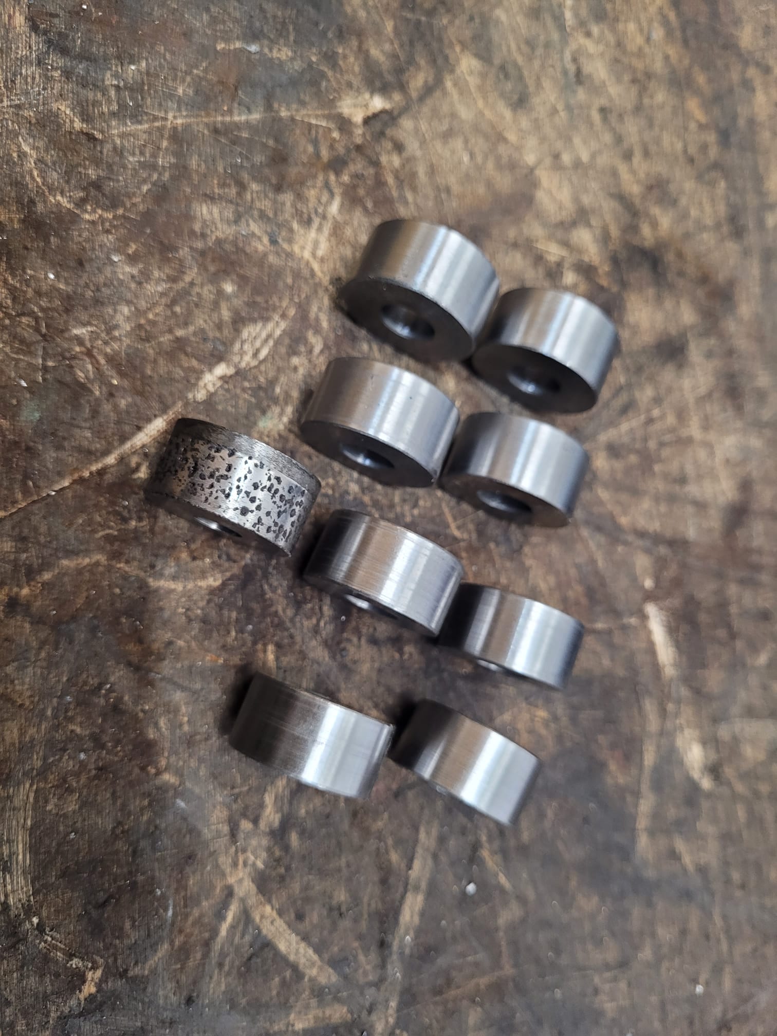
Below: Eight new followers, with one old one for comparison.
The aim remains to complete this programme of work on the Armstrong Whitworth car, along with some cosmetic work to the bulkhead and canvas roof, in time for Whit Week in May.
Photographs by Phil Doran, Paul Jarman and Phil Smith


very interesting update, thank you
Very interesting and thank you for sharing love your transport blogs.
will the steam mule run this year as it would be very interesting to see her running especially on Saturdays when im volunteering and it would add a Thame to the pit Village.
Hi Jamie
There are no plans to use the Steam Mule at present. It has been removed from the inspection cycle as preparing it each year for the surveyor, for it to only operate on very few days, was deemed to be an area we could save our resources. This is not to say this is a permanent arrangement, it is just to ensure we can focus on the other exhibits.
Best wishes
Paul