
Motoring and Motorcycling in the early years…
Last week Beamish reopened, though not without a few dramas along the way (as might be expected when waking any site from a period of dormancy I suppose!). As a result I haven’t compiled very much news for the blog yet, but have been very fortunate that Ian Bean, one of the Friends of Beamish directors, volunteer and also a member of the Town staff, has prepared an article for the blog which I am sure readers will find fascinating. He has also prepared a large number of images to illustrate this piece, so at this point I will pass over to Ian…
Motoring and Motorcycling in the early years, by Ian Bean
We take our modern, motorised world for granted. In the early years of the motor vehicle things were different. I thought I would look at the operation and management of powered, personal transport and its development, using some of the Beamish collection vehicles to illustrate the process. This is not intended as an all-encompassing technical treatise, but I hope it will help explain the attraction of vehicles from the earlier part of the last century. Many readers will be well versed in the maintenance and operation of older vehicles, but I hope this article will offer an introduction to those less familiar.

Above image Copyright 2021 Daimler AG
If we take the Carl Benz three-wheeler (above), completed in 1885, as the first “car” powered by an internal combustion engine we can examine the progress and development of powered, personal transport. The train was king in 1885 and would remain the foremost method of long-distance travel into the 1950s. In August 1888, without telling her husband, Bertha Benz completed the first long journey in automotive history. The vehicle used was an improved version of the tricycle and travelled from Mannheim to Pforzheim completing a round trip of 180km. Bertha Benz demonstrated the practicality of the motor vehicle to the entire world, but the internal combustion engine was by no means established as its default power source at this time. At this stage internal combustion engines ran relatively slowly (generally much less than 1000rpm) and were quite bulky.
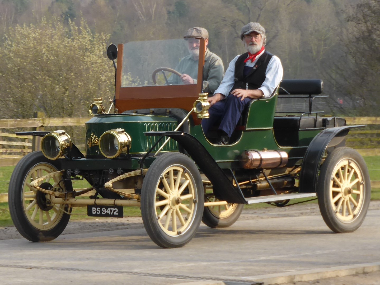
Above Stanley steam car. Image courtesy Claire Bean
Steam was a well understood power source, and the, then modern, electric motor was very appealing due to simplicity of operation. By 1900 the three power types remained equally well matched. Electric power was limited by the weight and range of the batteries available. Steam cars, like their internal combustion cousins, were generally powered by liquid fuels which could be difficult to obtain out of town and they had to stop for water every 30 miles or so.
Piloting a steam car is quite simple, managing the boiler safely and producing enough steam is much more complicated. Steam cars were extremely fast by the standards of the time and shared with the electric car the advantage of needing no gearbox due to their torque delivery. By today’s standards, the time taken to get your steam car ready, around 20 minutes from cold, seems an inordinately long time, but you were assured of successfully moving off at the end of the process. In the early 1900s the fickle internal combustion engine could be ready sooner but could equally turn its driver in to a physical wreck as they struggled to get it started!
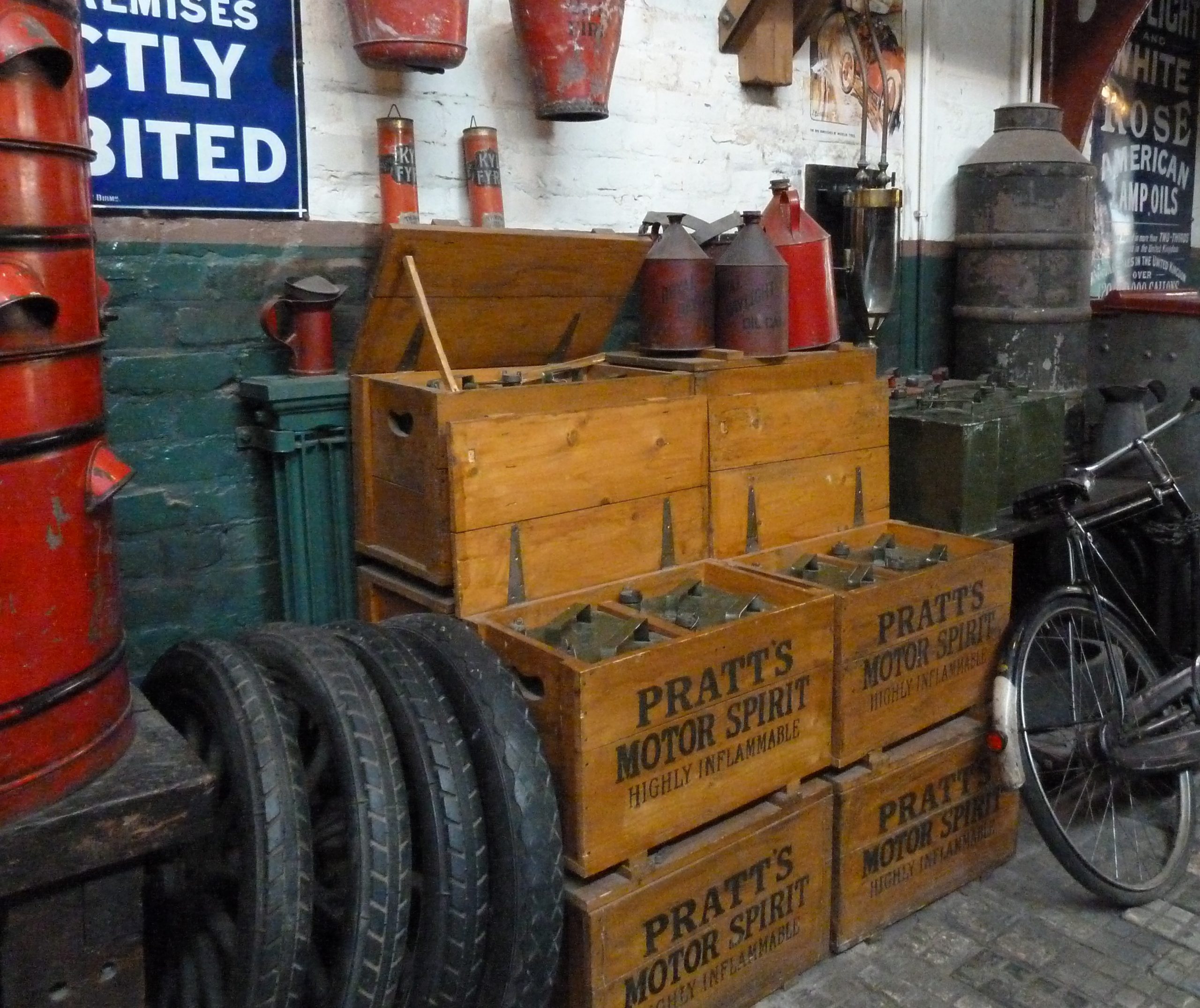
Travelling any sort of distance on the roads of the time was fraught with difficulty. Pneumatic tyres were very prone to punctures on the terrible road surfaces. Horse-shoe nails were prevalent everywhere and in wet weather the roads often became impassable. The pioneer motorist tended to be quite wealthy with the consequence that journeys became challenging, fun expeditions. Around 1900 you had the benefit of a well-developed rail service, so your luggage, fuel and spares could be sent on ahead, as indeed could your car! Spares, fuel, extra tyres, and a well-stocked tool kit were essential to include with your picnic hamper.
In 1919, the AA opened the first English filling station in Aldermarston, previously fuel came in 2-gallon cans from garages, chemists, and hardware stores. The AA was trying to promote the sale of British-made benzole fuel – a by-product of burning coal – as an alternative to imported Russian petrol – 7,000 pumps were in use in Britain by 1923. If you were disinclined to get your hands dirty a chauffeur was also a useful addition. Cars and motorcycles came with tool kits as the manufacturers expected the owners, or their employees, to carry out regular maintenance. The tool kits supplied by higher quality makers were often beautifully presented, in purpose made cases, fitting into the boot of the vehicle, or carried on the running boards.
Motorcycles started to become more viable around the turn of the twentieth century and we shall see that they brought the joys of the open road to a wider audience along with some extra challenges!
The internal combustion engine in action…
You need a fuel and a means of mixing it with air so it will burn in a cylinder. A method of igniting the mixture at the right moment is required, coupled with a means of dissipating some of the heat produced during the burning operation (roughly the same amount of petrol is wasted in the cooling process as is used to drive the car and even more disappears out of the exhaust). Lastly a method of lubrication must be provided to ensure the working parts remain free to interact with each other.
I will continue this section with a little more background information to set the scene.
For the purposes of this article, I am assuming that our internal combustion engine is fuelled with a relatively easily vaporised liquid. I will also assume that it is a four-stroke engine where the piston completes four strokes moving from the top to the bottom of the cylinder and back, twice for each cycle and the admission and exhaust of the gases is controlled by valves. The four strokes are in order (induction stroke) where the fuel/air mixture is drawn into the cylinder as the piston moves down. This mixture is then compressed (compression stroke) by the piston returning to the top at which point the mixture is ignited and the piston is pushed down the cylinder again by the expanding gases (power stroke). The final (exhaust stroke) allows the burnt gases to be expelled as the piston returns upwards.
Compression ignition engines (diesel) tended to be large, slow revving and too heavy for motor cars until the 1930s. Your modern car, if you still own an internal combustion version, relies on an electronic brain to ensure that the fuel mixture and spark timing are continuously optimised and in some cases the valve timing is also under its control. Until the 1970s much of this was left to the driver and in the eras concerning us, all of it was!
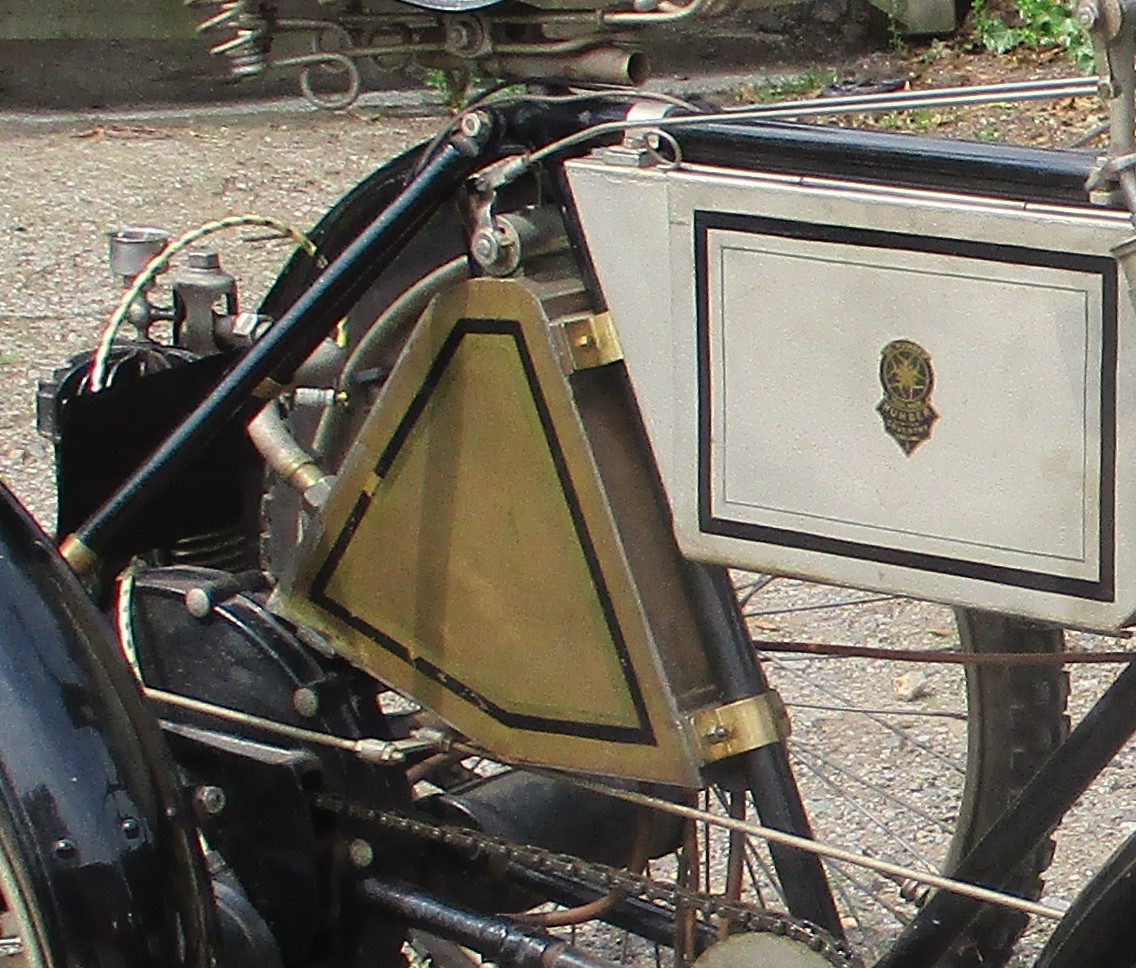
Fuel Mixture – internal combustion engines require a “rich” mixture when starting from cold. If over a certain age, you will remember using the “choke”. The variable mixture of fuel to air is often referred to as lean or rich. The ideal mixture when all the fuel is burned is called the “stoichiometric” mixture. This is difficult to achieve in practice, due to the limited time available for the combustion process. The fuel/air mixture was controlled using a carburettor device and these came in several types working in different ways. The surface carburettor as used by De Dion and Minerva was popular.
The De Dion version was basically a box which acted as a fuel tank and carburettor, but which could be supplied by an additional, long-range fuel tank. Air entering down a “chimney” was directed across the surface of the fuel which evaporated and filled the space above the liquid. The design allowed the chimney height to be adjusted as the fuel level fell, and exhaust gases were used to gently warm the mixture. An air control valve on the top provided a means of diluting the (hopefully over-rich) mixture on its way to the engine. In the De Dion version (as fitted to the Beamish Humber Quadricycle) there is also provision for a throttle valve to control the amount of mixture.
By 1904, the surface carburettor had all but disappeared, being replaced by the spray carburettor which had been around since its invention by Edward Butler in 1884. Multiple carburettor setups became common to give increased performance and development continued until they were gradually replaced by fuel injection systems from the 1960s.

Getting the fuel to the engine – Early motor vehicles relied on gravity to ensure fuel flowed to the carburettor. Motorcycles have their fuel supply taken from the rear of the tank so that the last few drops will be available on any uphill road. If you look at veteran and vintage vehicles, you will often find the fuel tank in the dashboard area. This normally entails it being above and behind the engine or directly in front of driver and passenger neither location being ideal from a safety perspective.
The Ford Model T has its tank under the front seats which became a popular location particularly on larger cars where a bigger tank was required. The Ford T still relied on gravity which can lead to embarrassment when ascending a steep hill with a tank less than half full. The consequent fuel starvation could be cured by reversing up the hill! More expensive makes, and often those of a sporting nature, used a hand pump to pressurise the fuel tank allowing fuel to flow even from a rear mounted tank. This was in some cases supplemented by an engine driven air pump once the engine was running. Cooled exhaust gases were also used to pressurise the tank in some designs.
A safer system was using a vacuum to draw fuel to the engine. One popular system was the Autovac, which used the vacuum created in the intake manifold to draw fuel from the tank. The Beamish Austin Twenty hearse uses an Autovac to draw fuel from its under-seat tank. Engine driven mechanical and electric pumps took over from the Autovac. The Wills Sainte Claire of 1924 employed an electric pump.
Ignition Systems – Hot Tube A platinum tube, passing through the cylinder wall and heated by an external flame was used by several early designers and could even vary the ignition timing slightly by increasing or decreasing the temperature of the burner flame. As engine speeds increased the deficiencies of this system became more apparent and designers moved on to Low Tension and then High Tension, Magnetos, or coil ignition systems. Low tension systems rely on the desire of an electric current to keep flowing as long as possible once started. When the circuit is broken this desire causes an arc across the ends of the break.
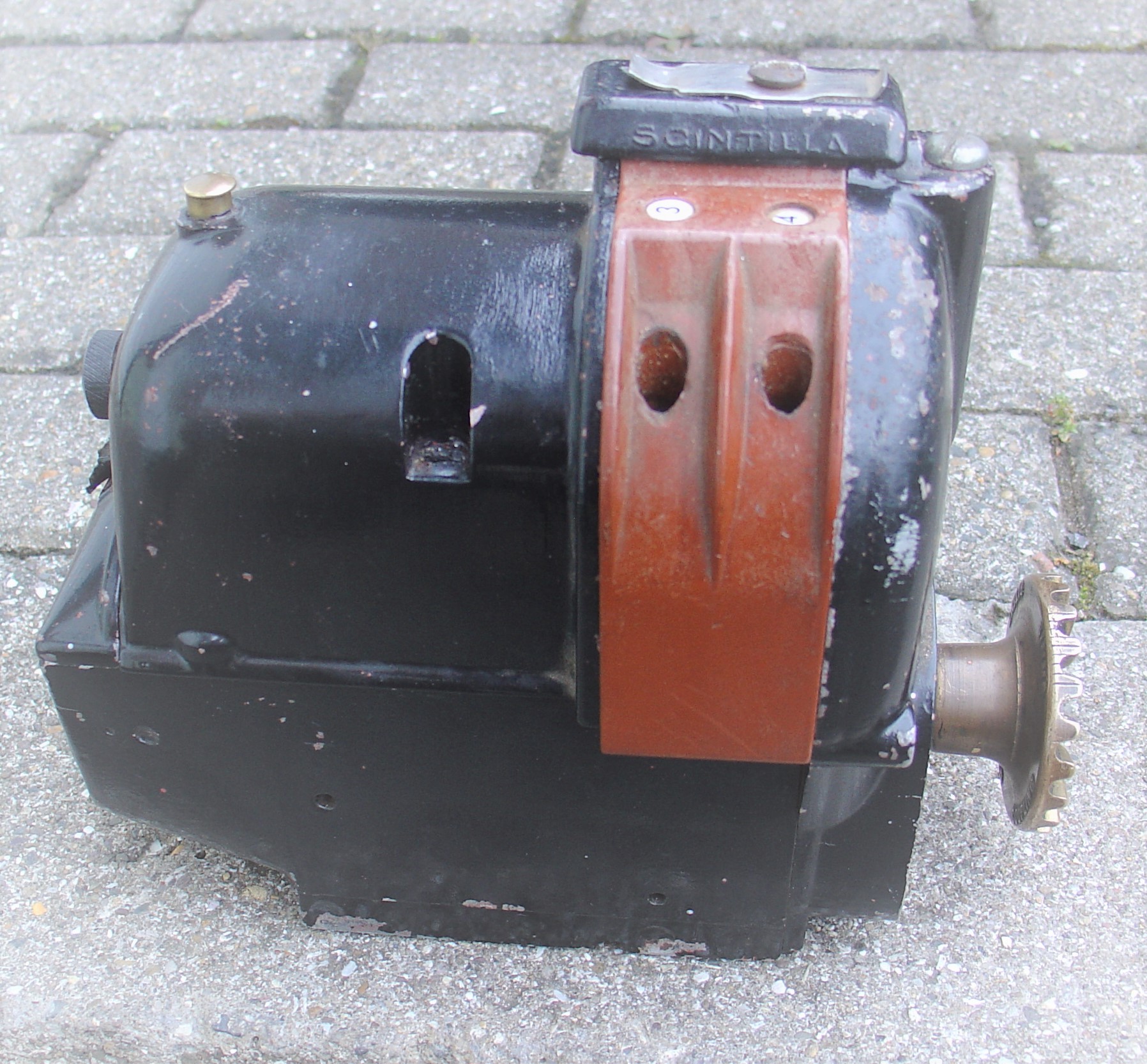
The break was made by a set of contacts which moved within the combustion space at the desired moment. The Low-Tension ignition could be powered by a battery, or by a built-in generator (the Magneto). Robert Bosch made a low-tension magneto in 1897 which provided a sparking current without the need for a battery. A year later Frederick Simms came up with several mechanisms to allow the position of the ignition cam to be varied in relation to the camshaft, providing variable ignition timing known as the Simms-Bosch L.T ignition system. Frederick Simms gave us the expressions “motor-car” in 1896 and “petrol” around 1890. Petrol was devised as a trade name for petroleums, also known as gasoline, motor-naphtha or essence refined by Carless, Capel and Leonard. He worked with Daimler and Bosch and founded the Automobile Club of Great Britain and Ireland in 1897, which later became the Royal Automobile Club. Simms magnetos are to be found on many vintage machines.
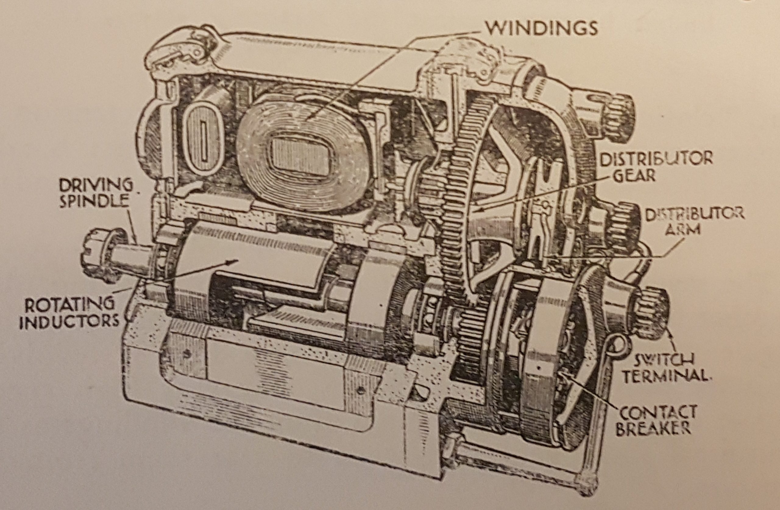
This system stayed in use, alongside the trembler coil system, until Robert Bosch produced the High-Tension magneto as a commercial proposition in 1903. The High-Tension magneto developed from the low-tension magneto combined with the induction coil. It continued to be the ignition system of choice on most European cars until the 1930s. A rotating armature produced a low voltage generator, where current flows when a contact breaker (the points) at the end of the armature is closed. The secondary winding surrounds the primary and is connected through a distributor to the sparking plugs.
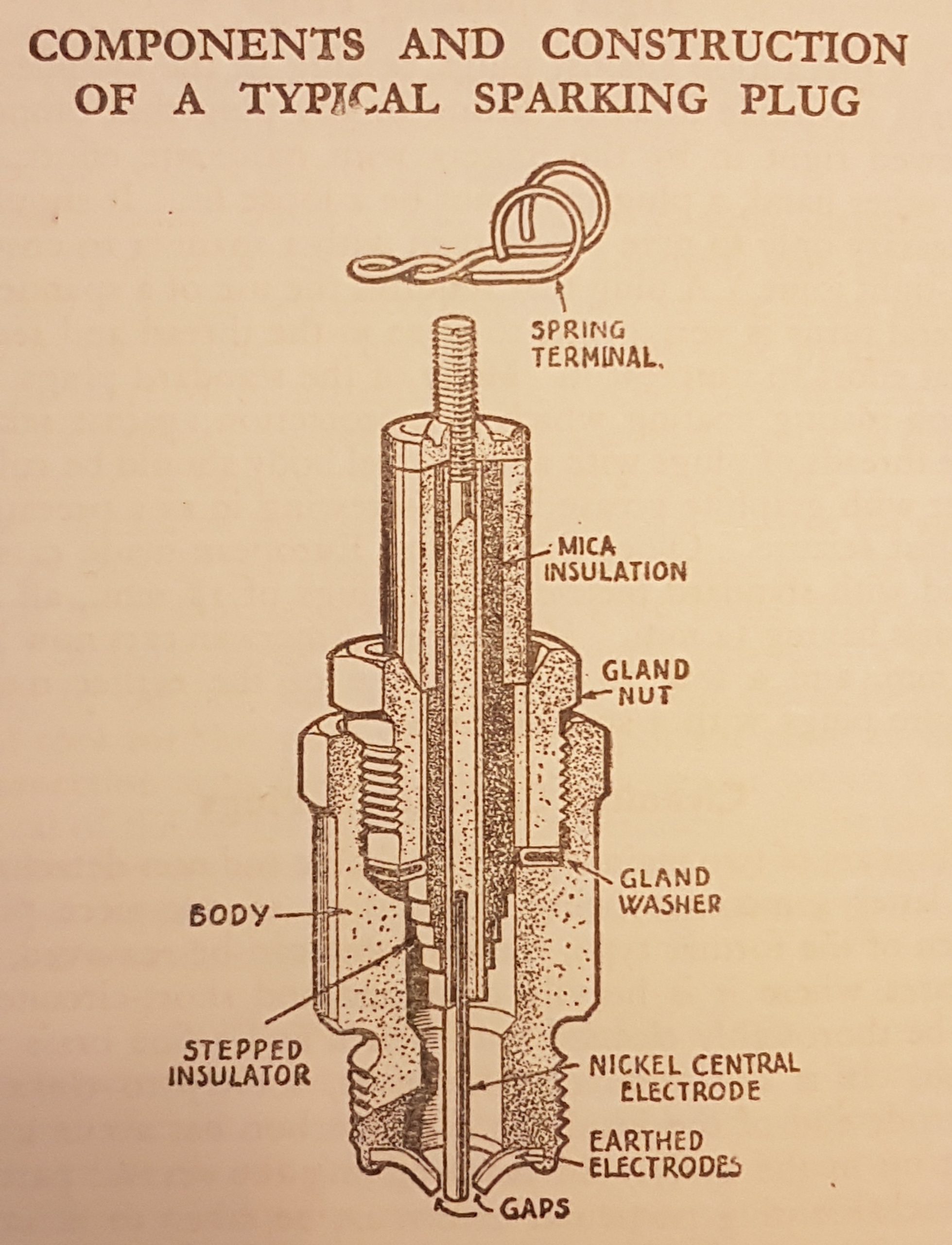
Trembler coils – the spark producing coil was commercially produced by French mechanic Ruhmkorff and used by Etienne Lenoir on his gas engine in 1860 initiating the electric ignition system and inventing the sparking plug. In the trembler coil, primary and secondary windings are wound on a bundle of soft iron wires in a similar fashion to the laminated armature of the magneto. The primary coil is connected to a battery through an interrupter or trembler. This was made of a thin spring steel blade fixed to the casing at one end and had a piece of soft iron at the other. A contact at the mid-point of the blade met an adjustable contact attached to the coil casing.
When the current is on it flows through the contacts and the primary winding. This magnetises the core attracting the soft iron to the blade causing the contacts to open and switch off the current. The magnetism then ceases, the blade springs back and the whole cycle starts again. If you think of an electric bell working, the speed is similar. The continual change in the magnetism of the core induces a high voltage current in the secondary winding. This is strong enough to produce a stream of sparks across the points of a sparking plug. The trembler coil system, first fitted to the Benz single cylinder in 1896, was quite popular. It was notably used in the Model T Ford, with the four tremblers mounted in an easily accessible box on the dashboard, one trembler for each of the four cylinders. In the Ford T the primary current is produced from a flywheel generator.
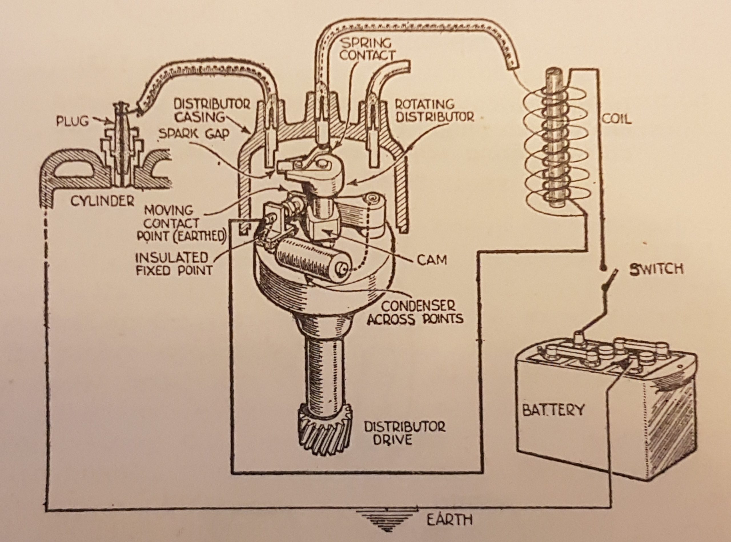
Coil systems are in principle similar to tremblers, but without the trembler contacts. A laminated iron core has the High-Tension winding of 15,000 to 30,000 turns of wire wound on it. On the outside of this, and insulated from it, is the primary winding made up of a few hundred turns of much heavier wire. One end of the primary winding is connected to a battery. The other end of the primary is attached to one end of the secondary winding and to a terminal fixed to the contact breaker. The remaining H. T. connection leads to the distributor and feeds to the relevant spark plug via a rotor arm.
Batteries were expensive and charging systems marginal, at this period, which might explain the magneto’s continued popularity as the vehicle could be started even if the battery was flat – remember the driver provided the power to turn the engine! Although the magneto has the advantage of not requiring a battery it does need to be rotated relatively quickly to produce a good spark and this can be difficult to achieve when hand cranking a large engine with good compression.
Farm tractors and industrial machines continued to use magnetos longer than most other applications and to make starting easier they employed a device called an impulse coupling which used spring loaded cams to allow the magneto to momentarily lag behind the engine and at the correct moment of firing the spring flicks the magneto, creating a good spark even if the engine is turned slowly. Listen for the audible click when vehicles so equipped are started by hand. Quality and sporting car makers often featured dual ignition systems using a coil and a magneto to provide power to two sparking plugs in each cylinder.
Lubrication – Early internal combustion engines followed steam engine lubrication practice using a total loss system often fed from glass oilers which allowed oil to be supplied to bearings and rubbing surfaces via an adjustable drip feed. As crankcases became enclosed, the moving parts such as the flywheel, could be utilised to splash the oil around and splash oiling remained an integral part of engine lubrication for many years. It was often supplemented with sets of adjustable drip feeds, with glass sight tubes, located on the dashboard (see SHEW car in Town Garage). Fresh oil was introduced regularly, and excess found its way out through the bearings or exhaust.
The Ford Ts at Beamish have had additional scoops fitted to their big ends and extra oil supply pipes to the front main bearings, a common improvement often added to the Model T during its working life.
As time progressed pumps replaced splash, picking oil up from the bottom of the crankcase and feeding it to bearings or, as employed in the Austin 7 of 1922, to jets which squirted oil into holes in the connecting rod big ends each time they came past. Oil pressure gauges were prominently positioned on dashboards so that the driver could take immediate action if a problem was indicated. Oil tell tales were also used to give a visual indication that oil was circulating, and pressure being maintained, a far cry from the modern oil warning light.

Oils were not as technically advanced as the products available today and were generally of monograde varieties. Oil viscosity can change considerably with temperature and thin oils were used in winter when the engine would be harder to turn over in cold conditions. A thicker grade would be used in the summer months to avoid the oil becoming too thin in the warmer weather. A multi grade oil is designed to offer the best of both worlds.
Modern oils have detergent additives in them removing waste products from the engine which are collected in the oil filter. Oil filters were not used in older vehicles, a metal gauze was generally fitted to collect the larger pieces of debris, so detergent oils can cause more harm than good in older engines, loosening impurities without any filter to remove them from the system. Oil changes would be carried out every 500 – 1000 miles depending on the severity of driving. The image below shows the oil filtering system in the garage display at Beamish.

Motorcycles continued to use total loss lubrication into the 1930s using manual oil pumps and mechanical ones to supply oil often via a sight glass allowing the rider to see oil being delivered.
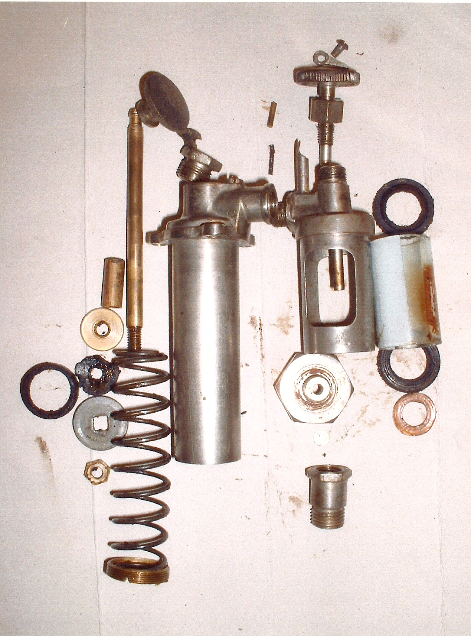
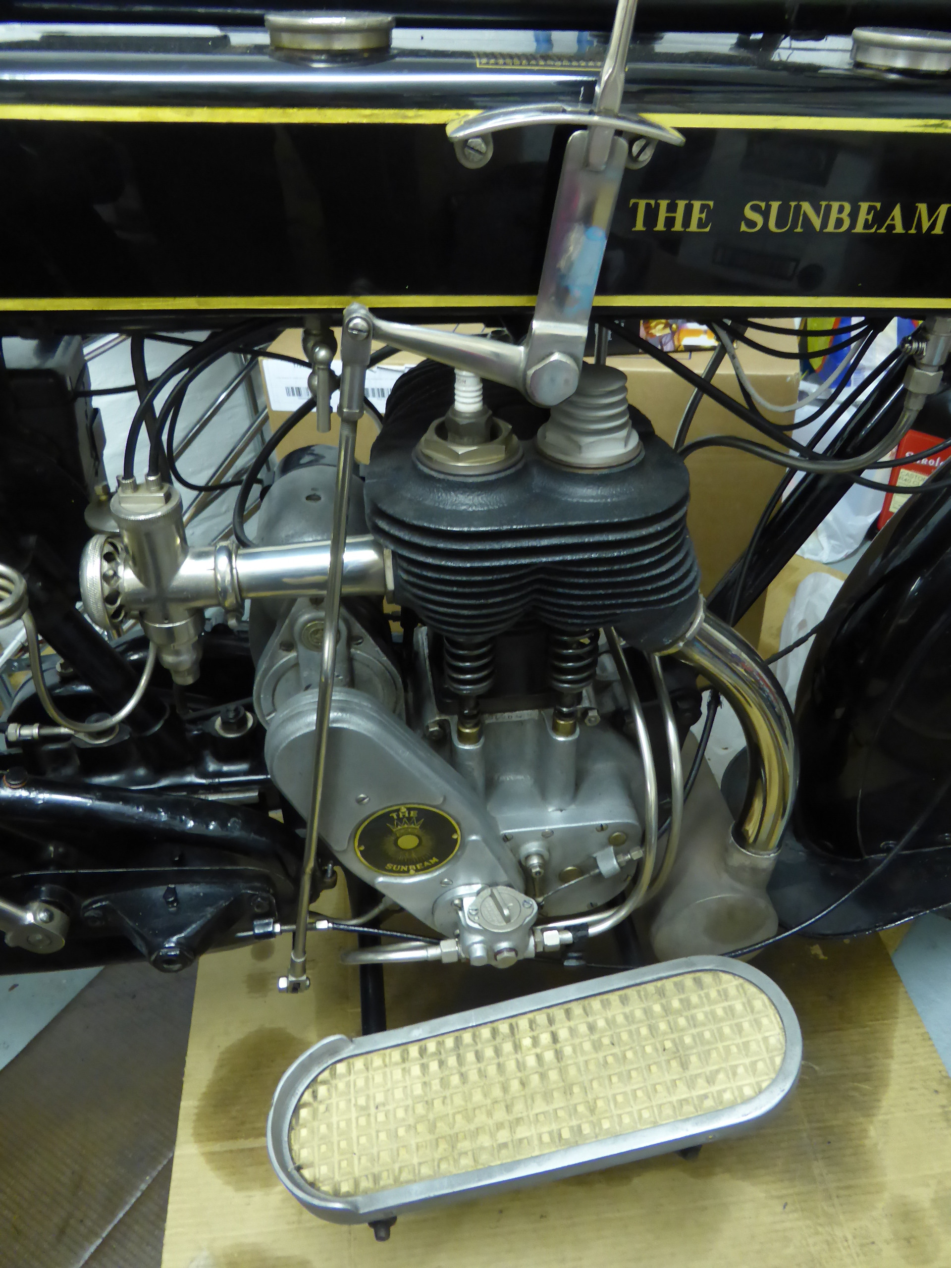
Above: These images show the Excelsior motorcycle manual oil pump components and the Best & Lloyd Mechanical oil pump on a 1926 Sunbeam.
Low maintenance was not an option to the motorist at this time with most vehicles being covered with oil and greasing points requiring daily, weekly, and monthly attention. As technology improved centralised lubrication points were fitted to assist the driver. In these systems oil, or grease, could be applied from one place either by hand, or by powered means, being distributed to the required area via a multitude of pipes.
Oil seals, if fitted, were generally made of felt or leather and were nowhere near as effective as today’s seals. Axle end seals often leaked requiring brake linings to be regularly cleaned in petrol to maintain efficiency. Often grease points were equipped with Stauffer caps which can be given a quarter, or half turn, each time forcing the grease into the moving part. If your vehicle had a water pump fitted you also needed to refill it with special water-proof grease.
Cooling Systems – Early engines, generally of single or twin cylinder configuration, could use the passing air current to provide cooling and indeed air cooling has had many advocates, none more so than Ferdinand Porsche responsible for designing the V.W. Beetle. Surrounding the cylinders with water jackets also proved effective and the water could be led through tubes to facilitate cooling often in conjunction with a pump to circulate the water. Hot water is less dense than cold water so sets up a natural circulation known as thermo-syphon cooling which works well, provided the hot, top, part of the radiator is as high as possible above the cylinder jacket.
As body designs began to feature lower radiators, engine driven pumps and fans were added. Edwardian cars often featured open flywheels fitted with vanes drawing air through the radiator. Engines work more efficiently when hot, so shutters and blinds were fitted to restrict the air flowing through the radiator, speeding up the attainment of working temperature. Some were operated manually and others by thermostatic means.
The Rolls-Royce 20 hp is easily distinguished from its larger siblings by its horizontally arranged radiator shutters (just to confuse the last series of 20HP sported vertical shutters!). Leyland used a thermostat in 1914 and this practice continues today. The normal boiling point of water is lower than the ideal operating temperature for the internal combustion engine and in 1954 General Motors used a filler cap with a spring-loaded valve to increase the boiling point of the coolant to a more suitable temperature.
In the eras portrayed at Beamish, bus depots and garages would have a watering can ready to replenish radiators once they had been allowed to cool slightly – pouring cold water into a red-hot system can be very harmful. For the same reason it is better to drive over the top of a hill and some way down the other side allowing the faster moving air to have a cooling effect on the easier working engine, rather than stopping at the summit with a fiercely hot engine! Quite often the radiator cap has a temperature gauge built in, being always in the driver’s vision, any overheating tendency is easily spotted.
Maintenance – We expect an engine to run reliably for long periods today, but much intervention was needed in years gone by. Ignition and carburation needed frequent maintenance and de-coking was a regular task due to the poorer quality fuels. This was the removal of the cylinder head to clean away carbon deposits from the head and valve stems. The valves would be lapped in, using grinding paste on re-assembly, to ensure good compression was maintained. Check the display cabinets in the Town Garage for valve grinding sticks and the double ended tins containing course and smooth grinding paste.

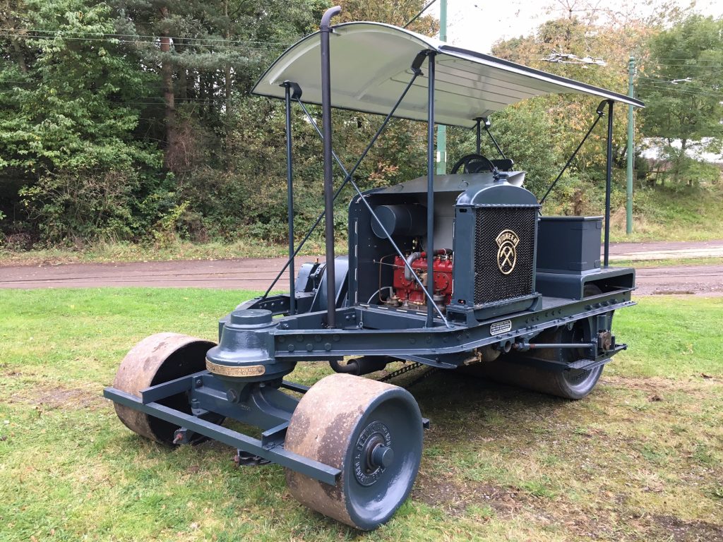
Above: Barford & Perkins motor, R025, roller four-cylinder Albion petrol engine, with the head removed.
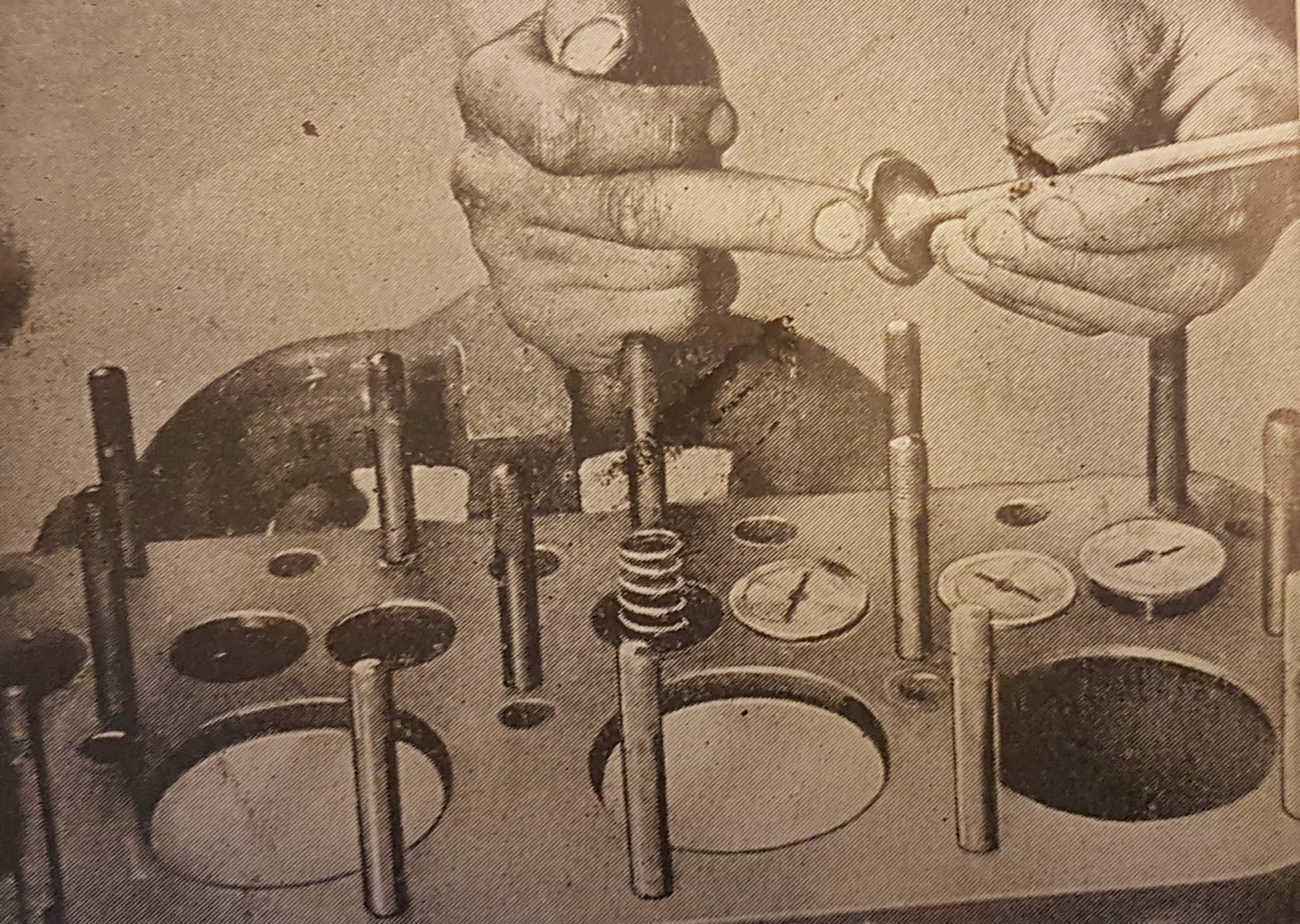
Above: Valve Grinding.
Getting the Power to the wheels
Transmission – At first flat belts were used as a primary transmission. The belt could be used to multiply the torque of the engine and by utilising a fast and loose pulley system this could provide a clutch, enabling the engine to run when not driving the car as well as allowing the drive to be engaged gradually. Additional pulleys and belts could be fitted providing a choice of speeds and this type of drive was good at absorbing shock loads. Final drive could be by gear or chain. Chain final drive made the accommodation of axle movement more easily achieved. Belts were not suitable for higher power outputs and took up valuable space.
Emile Levassor ran a woodworking machinery business with René Panhard and was a skilled engineer. He drew on familiar technology when their firm moved into making cars, taking the cone clutch, and sliding gear speed change, from machine tools, to replace the belt drive. He also placed the power unit in the front under a cover, with the crankshaft longitudinally arranged on the centre line of the chassis driving a transverse intermediate shaft through forward and reverse bevel gears.
The intermediate shaft was still connected to the rear wheels via chains. Twelve months later in 1895, they put the gears in a box to keep the oil in and the dirt out. The final step towards a modern transmission was taken by Louis Renault when in 1899 he changed from an intermediate shaft and chain final drive to use a propellor shaft, complete with universal joints driving a bevel pinion meshed to a crown wheel carrying a differential on the rear axle.

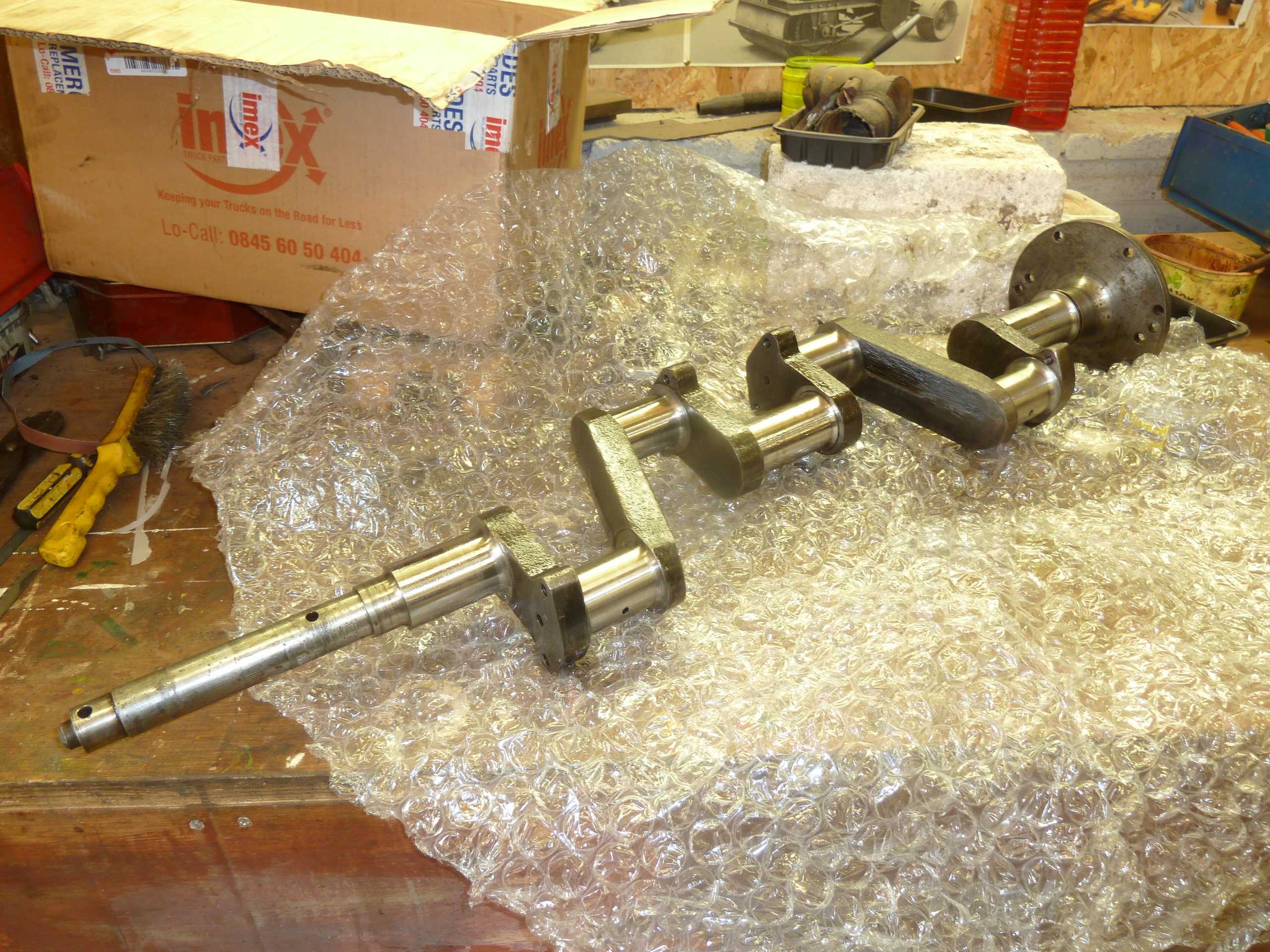
Above: A machined crankshaft (for the Albion engine in R025)
With this drive layout, where the crankshaft and gearbox input shaft are in line, a cone clutch could be fitted to the flywheel. This consisted of a tapered recess in the back of the flywheel into which a correspondingly taper rimmed disc could be forced by moving the gear shaft forwards. The tapered face of the disc was covered in leather which engaged sweetly when lubricated with neat’s foot oil and jammed home for full power delivery.
This type of clutch was large for a given power transmission and increased the weight of the flywheel, which inhibited gear changing. To overcome these disadvantages the multi-plate clutch of the Weston or Hele-Shaw types was developed. These featured several interleaved cast iron and phosphor bronze discs. The Hele-Shaw type was part plate and part cone. The multi plate clutch worked well with little momentum when released but it was prone to drag, particularly as it was run in oil to maintain sweetness.
Bugattis of the early 1920s used multi plate clutches as did the 1920 Armstrong Siddeley which was on loan to Beamish some years ago. It had a Hele-Shaw multi plate clutch which dragged with a vengeance – so much so that once on the move the only way to achieve silent changes was to leave the clutch engaged! Clutch stops could be fitted to stop the clutch revolving when released which also allowed gears to be selected silently when stationery.
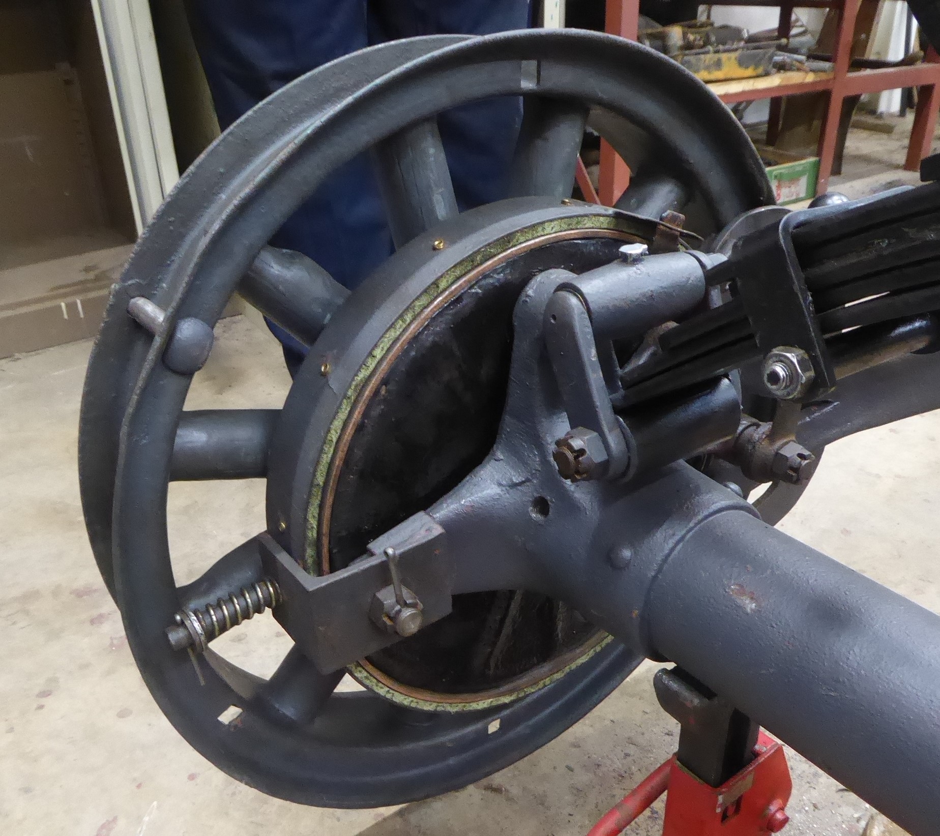
Above: The SOS clutch.
Friction material improvements, as pioneered by Herbert Frood, became available in 1921 meaning that the problem of sticking multi-plate clutches could be overcome using a single plate dry version. Clutches fitted with corks, often multi-plate, were used in motorcycles into the 1930s and belt final drives remained in favour, in fact the military often specified belt final drive for motorcycles. Many veteran motorcycles are fitted with Sturmey-Archer 3 speed hub gears incorporating a free engine position in essence a larger version of their bicycle hub gear.

Above: The Sturmey Archer 3 speed selector on Beamish’s 1912 Dene motorcycle.
The 1912 Dene at Beamish is fitted with such a hub gear with a separate pedal to control the free engine clutch. Smaller capacity motorcycles and small capacity cyclecars were sometimes single speed without a clutch. The rider simply pedalled away, or ran alongside, until the engine fired up at which point a swift step onto the foot board allowed the rider to take their place on the saddle. To slow down an engine decompressor could be used to lift the exhaust valve off its seat and to stop, the ignition could be turned off. The 1900 Humber Quadricycle (below) is of this design.
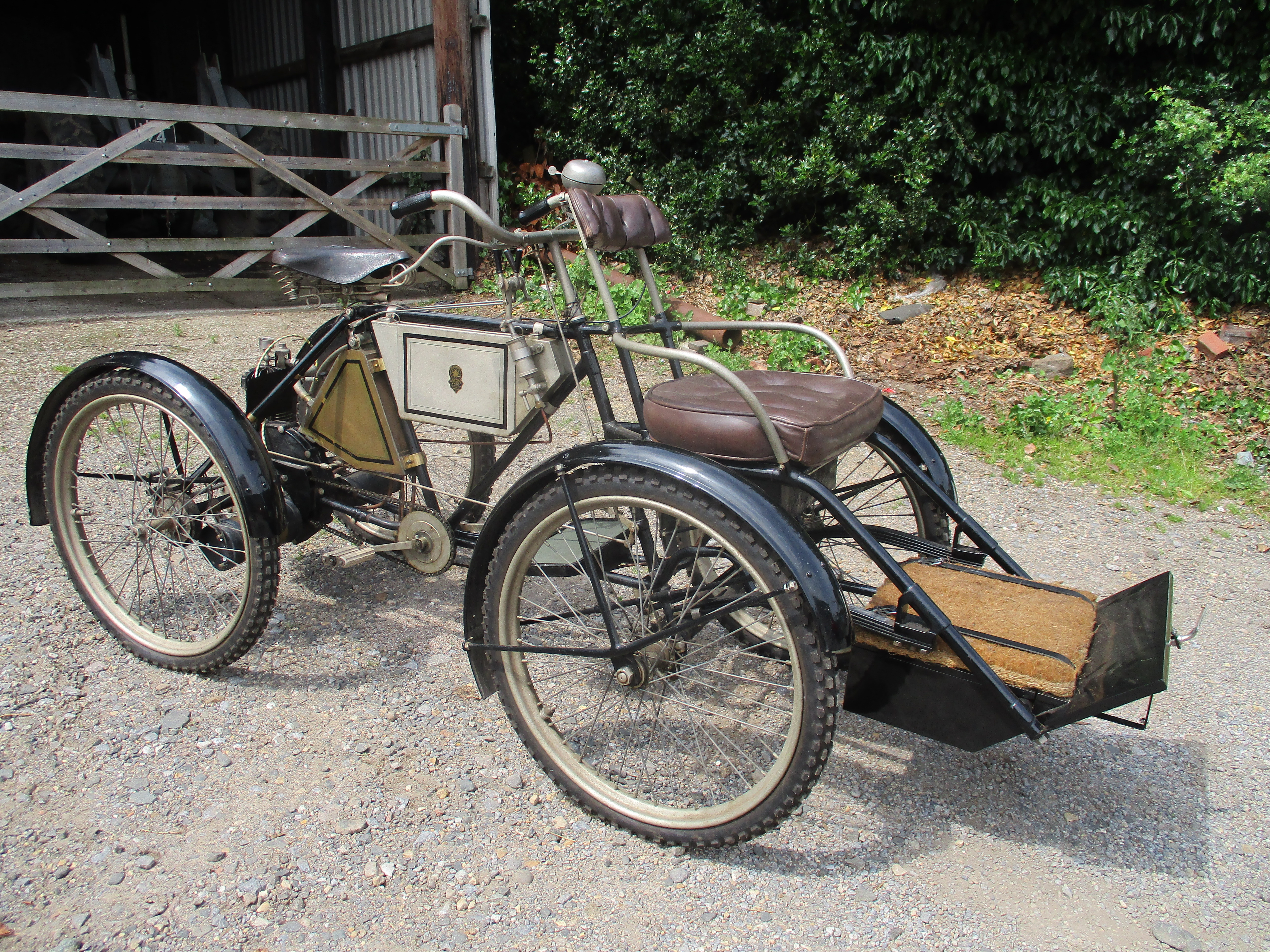
Above: Humber Quadricycle
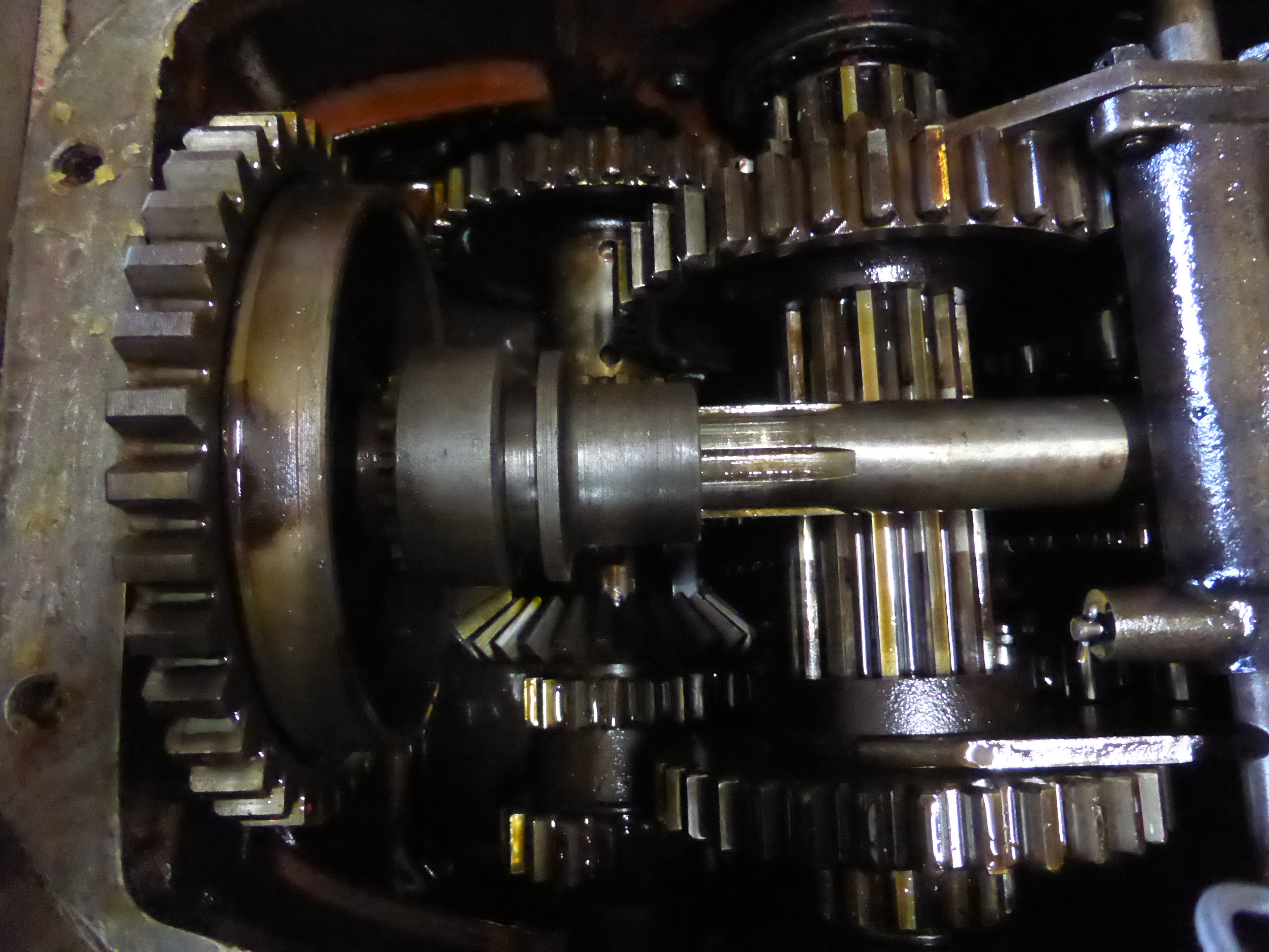
Above: An internal view of the Case Tractor gearbox
Countershaft gearboxes – Several chains with different sized sprockets, could be clutched in or out to provide a choice of ratios, but chains stretch and are difficult to lubricate if uncovered. Frazer-Nash successfully used a chain speed gear in their sporting cars in to the 1930s. In 1894, the countershaft (layshaft) gearbox came into common use in the Daimler engined Panhard-Levassor. In this type of arrangement there are two or three parallel shafts depending, whether the input and output shafts needed to be in the same line. Three shafts are used when input and output shafts are aligned and at opposite ends of the gearbox. Older vehicles tended to have clutches and gearboxes as separate units fixed to the chassis. The two-shaft gearbox has several gears rigidly fixed to the input shaft.
The gears correspond to the number of speeds, or ratios, to be employed. The other shaft, parallel to the input shaft, carries the same number of gears. These can move axially, whilst still in driving connection with the shaft or can be clutched individually to drive the shaft. In the first case, the gears are usually in pairs (clusters) and arranged so that only one pair can be meshed at one time. In the second scenario, the input and output gears are always in mesh (constant mesh) and the requisite gear on the output shaft can be coupled, or clutched, to the shaft.
Several sorts of clutches have been used with the most usual being a dog clutch. This is a sleeve with axial projections which can be slid along the shaft engaging with matching projections on the side of a gear. With this type of dog clutch, it is possible to use a synchronizing (synchromesh) mechanism to ensure that the two parts of the clutch are aligned and moving at the same speed. With other types, obtaining a smooth and quiet change is entirely down to the skill of the driver to adjust the relative speeds of the parts by double declutching. This is achieved by adjusting the speed of the driven shaft by throttle movement while the transmission is in neutral. Gears with straight cut teeth were used at first but helical teeth became common through the late 20s as they are stronger for a given size and much quieter.
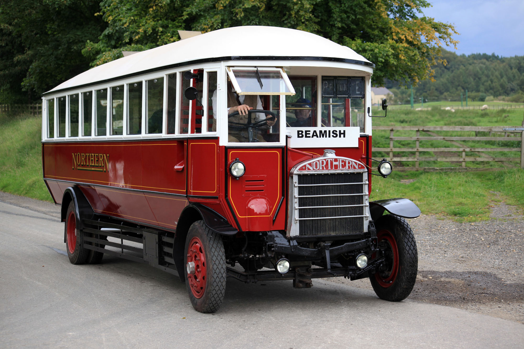
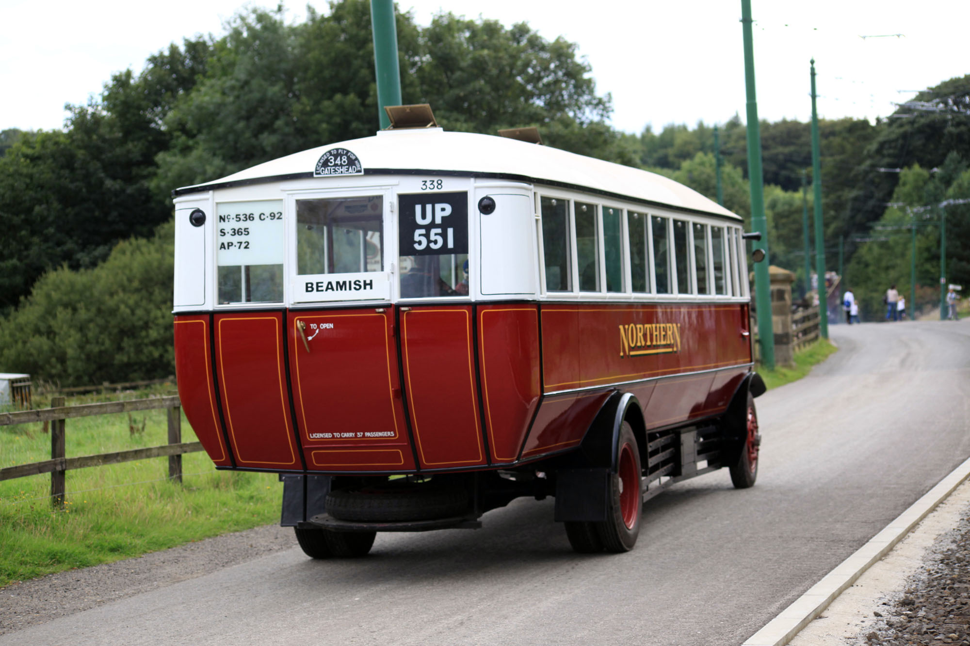
Did you know the Citroen double chevron trademark represents the double helical gear – the invention of which is credited to Andre Citroen? Straight cut gears are still used in racing cars as they can be used to reduce weight and produce no axial thrust. The Beamish SOS bus, features straight cut gears, producing a wonderful sound, and collected reminiscences suggest keen Northern drivers often dispensed with the use of the clutch, relying on getting the engine to road speed exactly right, for fast and silent changes.
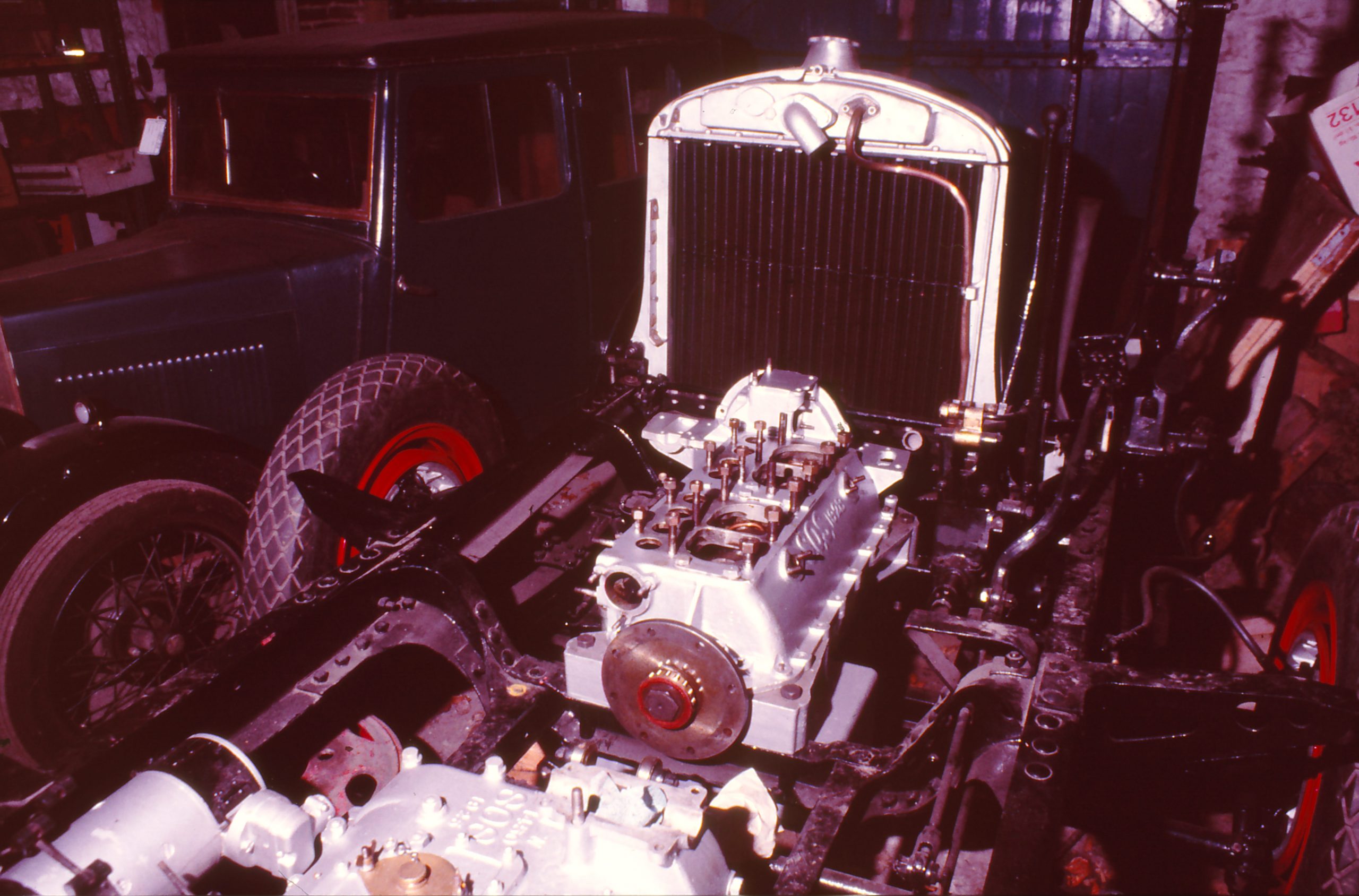
Above: The SOS Engine and Gearbox
Automatic systems don’t really concern us, but one other type of transmission which does feature at Beamish is the epicyclic system. This features on bus pre-selector gearboxes and of course in the Model T Fords. Epicyclic gear chains normally consist of a central sun gear, an outer gear with internal teeth – the annulus and one or more planet gears between them and held on a planet carrier. By holding differing parts of the system, the direction and ratio can be varied. In the Ford T two forward speeds, a reverse gear and a transmission brake are combined in the transmission.
![]()
Above: Model T transmission.
Gear selection – The early Panhard gearbox had a single shift rod and moving this rod moved all the gears into successive positions giving one gear ratio after another. All the ratios must be engaged in order, either changing up or down. This could be an inconvenience, but not a massive one – motor cycle gearboxes still work on similar systems. The next development was the gate change employing two or three selector rods are employed with selector forks engaging in grooves on the gear hubs. Spring loaded balls maintain the selectors in the correct position. Early mechanisms moved in a H shaped gate and this was superseded by a spherically mounted lever allowing any gear to be engaged from neutral.

Wheels and Tyres – At the dawn of motoring, solid tyres were fitted in a similar fashion to bicycles and some horse drawn vehicles. 1890 saw the development of both the wired bead tyre, the basic design of which is still used today, and the “clincher” or beaded edge tyre which became popular remaining in use till the middle 1920s. Beaded edge tyres have an outwardly projecting bead which engages with a matching inward bead on the rim clinching under the rim when inflated. As they have no wire in the bead, they can be stretched on to the rim using tyre levers, but this also means they can leave the rim easily when deflated and revolve on the rim under load or when under inflated.
If you look at the rear wheels of a car or motorcycle fitted with beaded edge tyres you may think they have more than one valve for inflation. One will be a valve, but the others are most likely Security Bolts used to provide additional location of the tyre. The wired bead tyre, as its name suggests has a non-extending steel wire making it difficult to fit to the rim. In 1891 Dunlop produced a rim with a well in its centre. This permitted one side of the bead to be placed in the well, giving space for the opposite side to be forced over the rim. Cord reinforcing was first used in car tyres around 1900.
Layers of overlapping cords were used and in time these plies were made into complete diagonal cords rather than strips and this design became known as the “crossply”. The same inventors, C.H. Gray and T. Sloper, suggested using non stretchable fabric cords set radially to the tyre with circumferential belts of fabric or wire – this design was revived by Michelin in the late 1940s and became the tyre we all use now the “radial”. Prior to 1904, tyres generally had a round tread section, from then manufacturers started to offer raised flat treads and soon corrugated ribs were added to provide non-skid properties.
The avoidance of the “dreaded side-slip” led to tyres with metal studs embedded in the tread. Rubber or leather clip-on protectors could be fitted over the tyre like an overshoe, chains or sash cord would be used in slippery conditions. Tread patterns were not scientifically designed and manufactures often cast their names as a tread. Firestone produced one of the more memorable patterns moulding in the words “non-skid” diagonally across the tread area. Many examples of these early tyre designs can be seen on the vehicles at Beamish and on display in the Town Garage.
Brakes – Being generous to the early motoring designers, it would be fair to say they spent much more time perfecting the technology of “going” as opposed to stopping! The front wheels of cars were left unbraked in the fear that this would affect steering. Spoon brakes were used at first, applied to the outside of the wheel rims and a “sprag” was often fitted. The sprag was a metal spike fixed to the chassis which could have its free end dropped on to the road where it would dig in to prevent the car running backwards on a hill.
Another, option was to apply a brake block or band to a part of the drive train. This type was known as a transmission brake and stayed popular for many years. The Model T Ford has a foot operated transmission brake and hand operated brakes on the rear wheels. This does give two independent means of braking but has the disadvantage of all braking being applied through the rear wheels. If a component failed in the transmission you could be left with only one system. Model T hub brakes are not renowned for their performance and in addition are much less effective in reverse, which can, at the very least, be embarrassing!
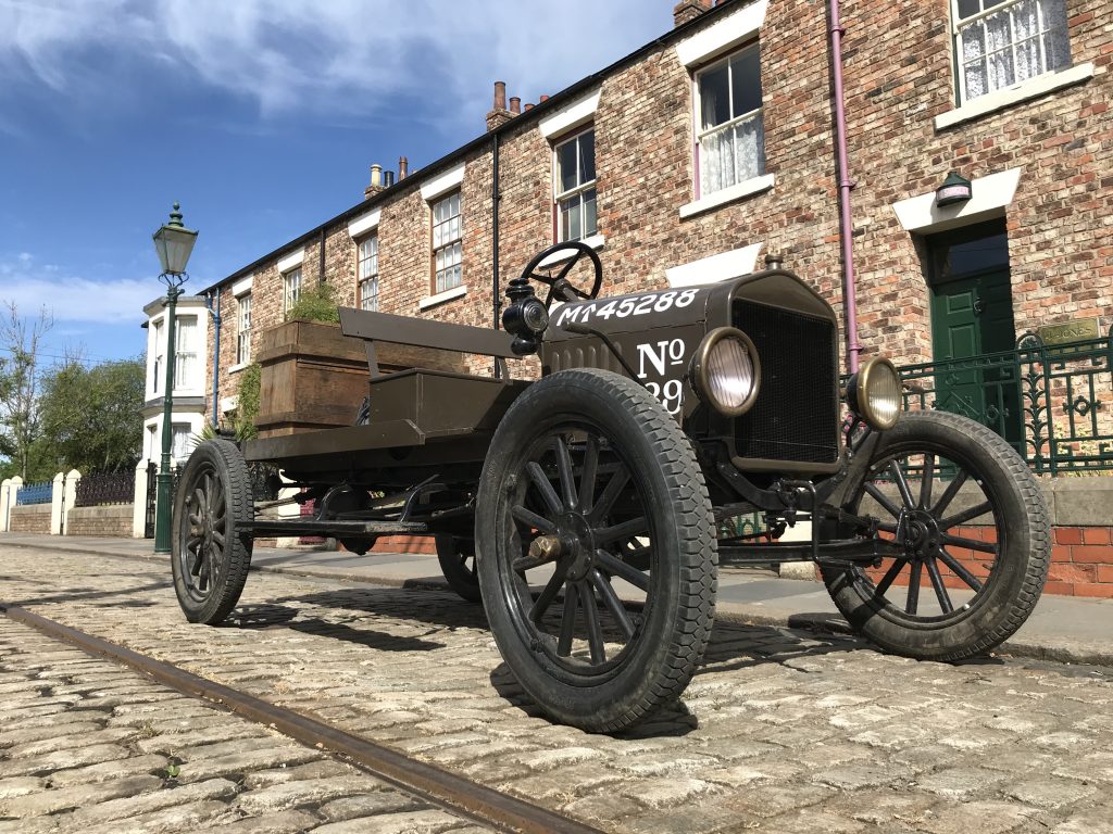
Above: Model T brake. Located on the rear axle of Beamish’s Model T Ton Truck.
As a vehicle is braked, weight tends to be transferred from the rear wheels to the front, so as vehicles got faster it became necessary to apply braking to the front wheels as well. This caused many problems especially with mechanical rather than hydraulic actuation. It was difficult to combine the brake operating linkage with the front wheels need to turn. Four-wheel braking systems ideally need a proportioning ability so that during braking, the more lightly laden rear wheels do not lock up.
There was such paranoia regarding front wheels locking and losing steering control, that the opposite bias was aspired to, even by Rolls Royce. The renowned manufacturer Crossley got into difficulty over their adoption of front wheel braking largely due to their system using the foot pedal to operate the front brakes only, with the rears being operated by a hand lever. As a service-brake, the fronts proved too effective resulting in uneven braking and a loss of steering.
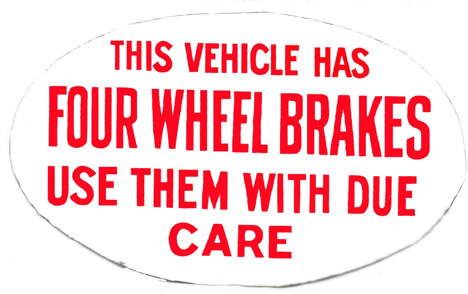
Vehicles equipped with four-wheel brakes were frequently fitted with warning signs to warn following vehicles of their superior stopping ability. Our SOS bus was one of the first commercial chassis to be so fitted using a hybrid hydraulic/mechanical system and the driver is provided with a warning sign in the cab to advise caution.
Steering – Early cars used a single front wheel, or a centre pivoted, turning front axle as used on horse drawn or steam vehicles to allow the front wheels to turn in arcs which have the same centre but of different diameters. It was easy to design steering with a centre pivoted axle and simply attach it to a tiller, but this was difficult to use at anything above walking pace. If a wheel met an obstruction the driver could be ejected from his seat!
To help alleviate this issue gears or chains were placed between the axle and the tiller. George Lenkensberger had produced a mechanism which allowed the wheels to swivel through different angles back in 1818. This became known as Ackermann steering because Lenkensberger passed the sole rights of his invention to Rudolph Ackermann a London bookseller and publisher. By the early 1900s designers such as C. E. Duryea and E. H. Gordon amongst others worked out that by angling the front stub axles away from the vertical in both camber and castor the steering could be made less sensitive to road shocks and given a degree of self-centring.
Even with the Ackermann system the steering could be snatched from the driver’s control by road-shocks, and it was soon realised that it would be better to have some irreversibility in the system. A screw and nut system later developed into the steering box, supplied this requirement. As several turns where required to go from lock to lock a steering wheel became a useful amendment.
Controls – There was little standardisation of control position in to the 1930s with the position of foot pedals and hand controls varying enormously from maker to maker. Many vehicles had the accelerator pedal in the centre as used in the 1928 SOS bus found at Beamish. Hand accelerator and ignition timing controls were generally fitted. American tractor manufacturers were very fond of hand operated clutches as seen on the Beamish Case Model C of 1937.
Gear change patterns varied, and motorcycles had brakes, clutch and gear controls fitted wherever the manufacturers felt best suited them. As an example, vintage Sunbeam motorcycles had the front brake operated from the left handlebar end as this was the same arrangement used on their bicycles. Often, gearchange and clutch were combined particularly on two speed motorcycle transmissions as in the “coffee grinder” control on the Beamish Royal Enfield. At first glance the Ford Model T pedal layout looks like a modern car but, looks can be deceiving!
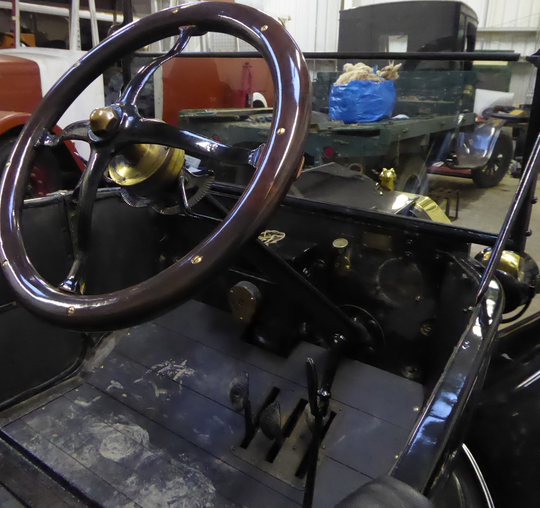
Above: Model T controls. Looking forward the left-hand pedal is a change speed High/Low pedal used in conjunction with the handbrake lever to control forward motion. The centre pedal is used to select reverse, and the right-hand pedal operates the transmission brake. Two hand levers on the steering column act as accelerator and ignition timing controls. You will often find a choke control fitted at the front of the vehicle conveniently close to the starting handle.
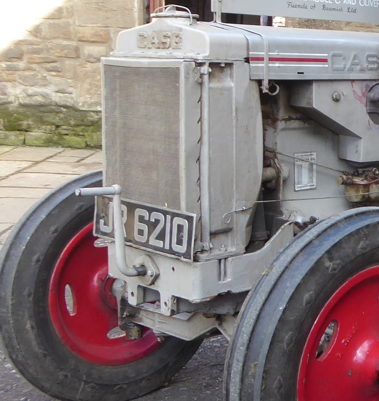
Above: The Case tractor starting handle and choke control accessible from the front.
Most items could be accessed from under the bonnet as before electric starters the driver would be at the front operating the starting handle. Heating and ventilation systems were considered unnecessary or as optional accessories in to the 1960s. Ventilators and opening windscreens allowed fresh air to be admitted and car coats and gloves kept the driver warm. Passengers could be supplied with hot water bottles and blankets during cold weather.
If you wondered why early cars were not always fitted with windscreens there are several reasons. A large screen added considerable weight and wind resistance to the often underpowered early car and before safety glass became standard you are sitting behind a large plate glass window with all the associated risks! Windscreen wipers were operated manually at first and then vacuum operated units were fitted. Their disadvantage was that the vacuum is drawn from the inlet manifold and tends to be greater when the engine is working hard with the throttle well open, generally this is at slower speeds. When cruising, in top gear at higher speeds, the wipers worked slowly due to the reduced vacuum!
Visible and audible warnings – Your new motor vehicle needed an audible warning system to alert other road users of your presence. Gongs or bells operated by the driver’s foot were used as they were less likely to frighten horses. Bulb horns and Klaxons provided more volume, and your car could be fitted with an exhaust driven whistle sounding like those fitted to steam vehicles. Lighting was at first provided by candle or oil lamps, although these were more effective for alerting people to your vehicle than allowing you to see the road! As road speeds increased, and night driving became more common, head lights progressed to using acetylene gas.
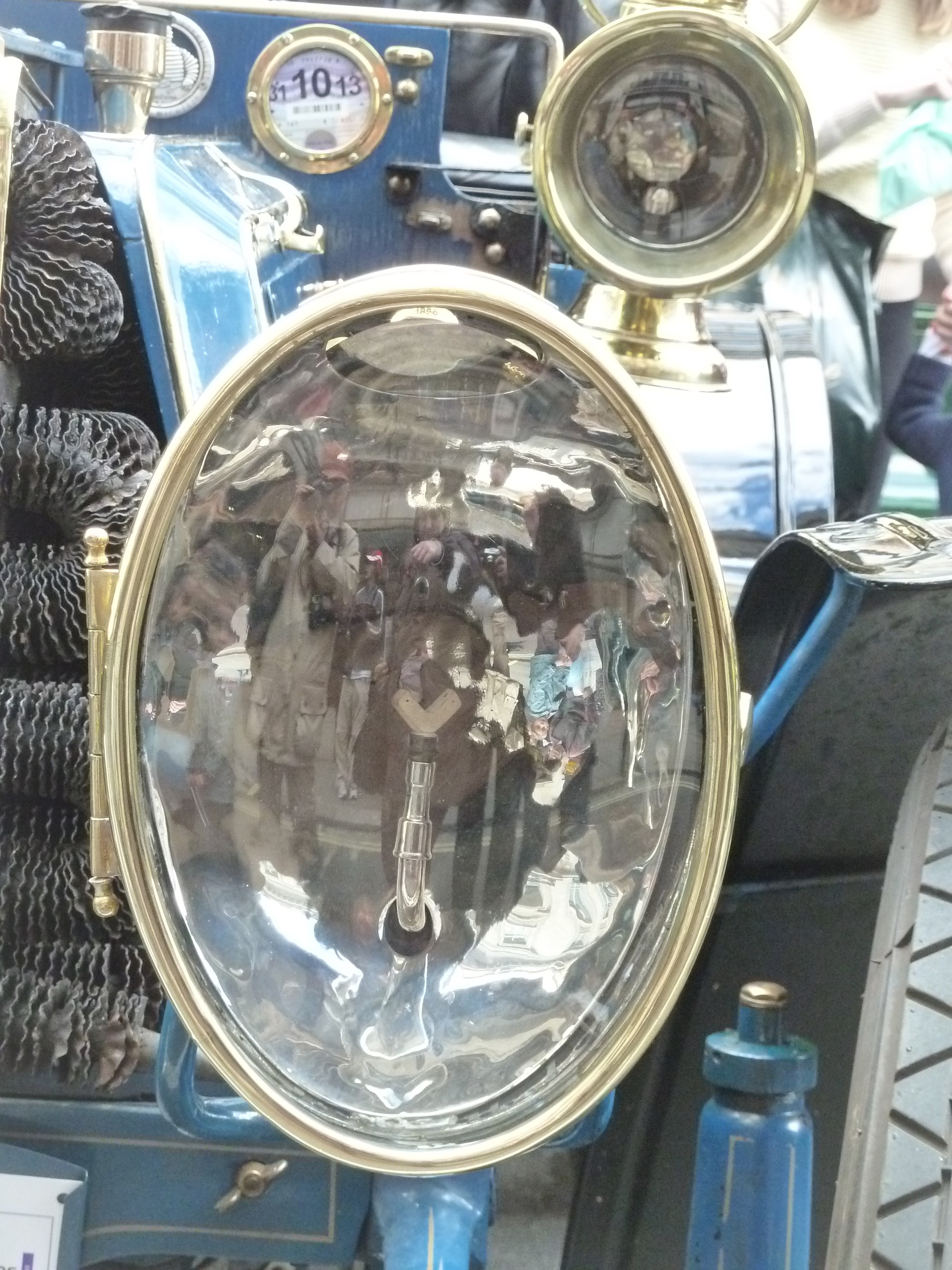
Above: An acetylene headlamp.
This was produced by dripping water on to calcium carbide. The gas generator could be a separate assembly or built into the lamp and the gas was burned in ceramic burners often with two flames facing each other giving a very bright clean flame. Good acetylene lamps were quite effective and provided reasonable road illumination, particularly when the light emitted was reflected of the, generally, dusty road surface.
The petrol-oxygen lamp was also used. In this system oxygen was passed through a mixing device containing petrol. The resultant flammable gas was passed to a burner where the flame played on a thorium oxide disc, which incandesced giving a brilliant light. Oncoming drivers complained of being dazzled by these bright lights leading to the invention of several anti-dazzle systems. By the outbreak of World War 1 electric lamps were becoming more common as motor cars started to be fitted with batteries and generators.
The change from delicate carbon filaments, to the much more robust tungsten type, made electric systems much more reliable and as it was no longer necessary to provide an escape path for hot gasses the reflector could be a more effective shape. Lamps could be dipped by physically moving them or a mechanism inside the lamp could move the reflector inside its shell using pneumatic or electromagnetic means. Local maker of high-quality motorcycles, N.U.T. adopted a Lucas electric lighting and horn system for their machines with the lighting control fitted to the rear of the fuel tank as seen on the 1925 machine in the Beamish collection. Hand signals were the order of the day at this period.

Actually Starting – Armed with all this background knowledge we are now ready to go for a drive in our motor vehicle or ride on our motorcycle. Having checked for fuel, oil, and water we need a rich mixture to start from cold. This is achieved by tickling the carburettor. This may sound odd, but a tickler fitted in the float chamber lid allows the fuel level to be raised well above its normal position.
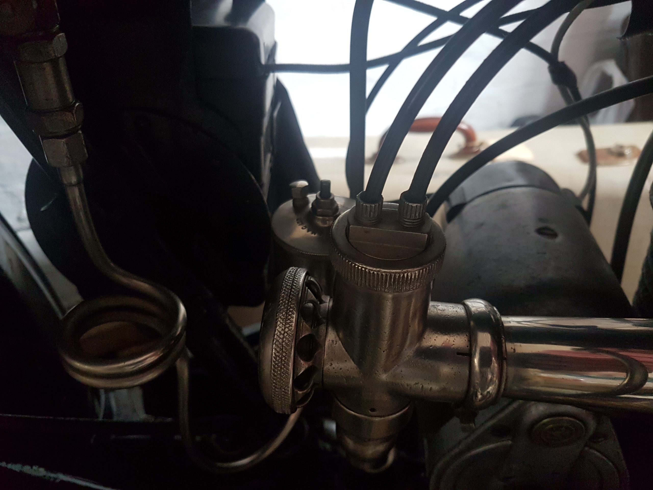
Above: The AMAC motorcycle carburettor with tickler in float chamber lid.
The engine can be turned over a couple of turns with the ignition off to ensure that the rich mixture has been drawn into the cylinder(s). Many early engines have priming taps fitted to allow a small amount of neat petrol to be added directly to the cylinder combustion chamber. With primitive oils this also helped clear sticky lubricant from the cylinder walls allowing the engine to turn more easily particularly in cold weather.
A choke control can be applied in addition to using the tickler, or instead of, if one is not fitted. The ignition control should be set towards its retarded position to prevent the engine “kicking back” when the starting handle is used. Every engine has its own preferred settings which the operator must learn! It is wise to keep your thumb out of the way and avoid pushing down on a starting handle as in the event of a backfire you want the handle to be thrown out of your grip and hopefully this will stop you experiencing a broken finger or wrist! The starting handle is then used to turn the engine over compression, and with luck and the correct settings it will burst into life.
The accelerator and ignition timing can then be adjusted to achieve smooth running. An electric starter was first fitted to the Arnold in 1898 but it wasn’t until 1912 that Cadillac really began its use. On smaller cars, and particularly 6 volt equipped systems, it was often the manufacturer’s recommendation not to use the electric starter when the engine was cold.
Above: Synchronized Kick Starting!
Motorcycles generally have a decompressor/valve lifter fitted and this can be used to assist the rider when they use the kick starter. The decompressor lever is released once the engine starts to turn allowing the flywheel to help carry the engine over compression. Kick starter is a slight misnomer as you apply a long swinging push with your foot, not a kick.
Above: The use of goggles is a sensible precaution when driving at anything above ‘very slow’ speeds.
Driving – Now that the engine is running, we can allow everything to warm through before setting out on our journey. If the weather is cold a warm coat and gloves will be required as previously mentioned heaters and demisters are many years in the future. Anticipation is vitally important when driving older vehicles as things tend to happen at a slower pace than those around you, especially acceleration and braking! However, there is no distracting radio, CD or MP3 player to worry about.
Having familiarised yourself with the controls you can now start to move off and at this point you will realise that the controls can be much less forgiving compared to a modern vehicle. If your vehicle does not have an electric starter try to avoid stalling as running round to the front can be embarrassing in heavy traffic! Gear changing on a crash box needs concentration and the adage of going down a hill in the same gear needed to climb it, is wisely remembered with the braking systems fitted to older vehicles. Narrow tyres and primitive suspension require careful piloting, but it is worth remembering the atrocious road conditions that older vehicles will tackle with comparative ease. Along with the actual driving you need to keep an eye on temperature, oil pressure, oil feeds and manage fuel mixture and ignition timing.
However, before long, you will have adapted your driving style to that of a more relaxed age. You may have mastered “heel and toeing” using one foot on accelerator and brake pedals simultaneously to achieve good gear changes and hopefully, the experience of driving an early vehicle will be causing a broad smile to spread across your face. Enjoy the moment before you get back to the maintenance!
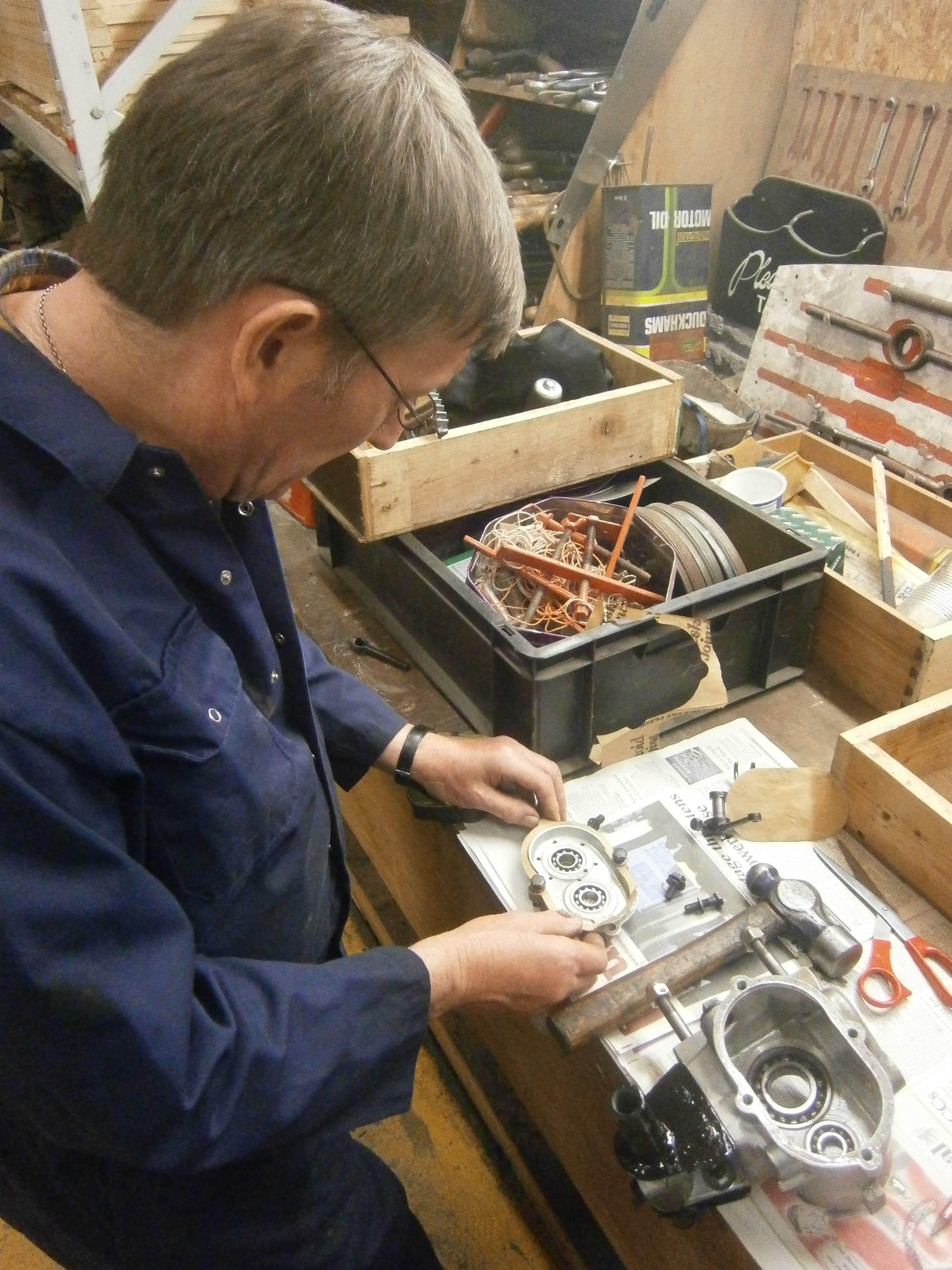
Above: AJS gearbox overhaul.
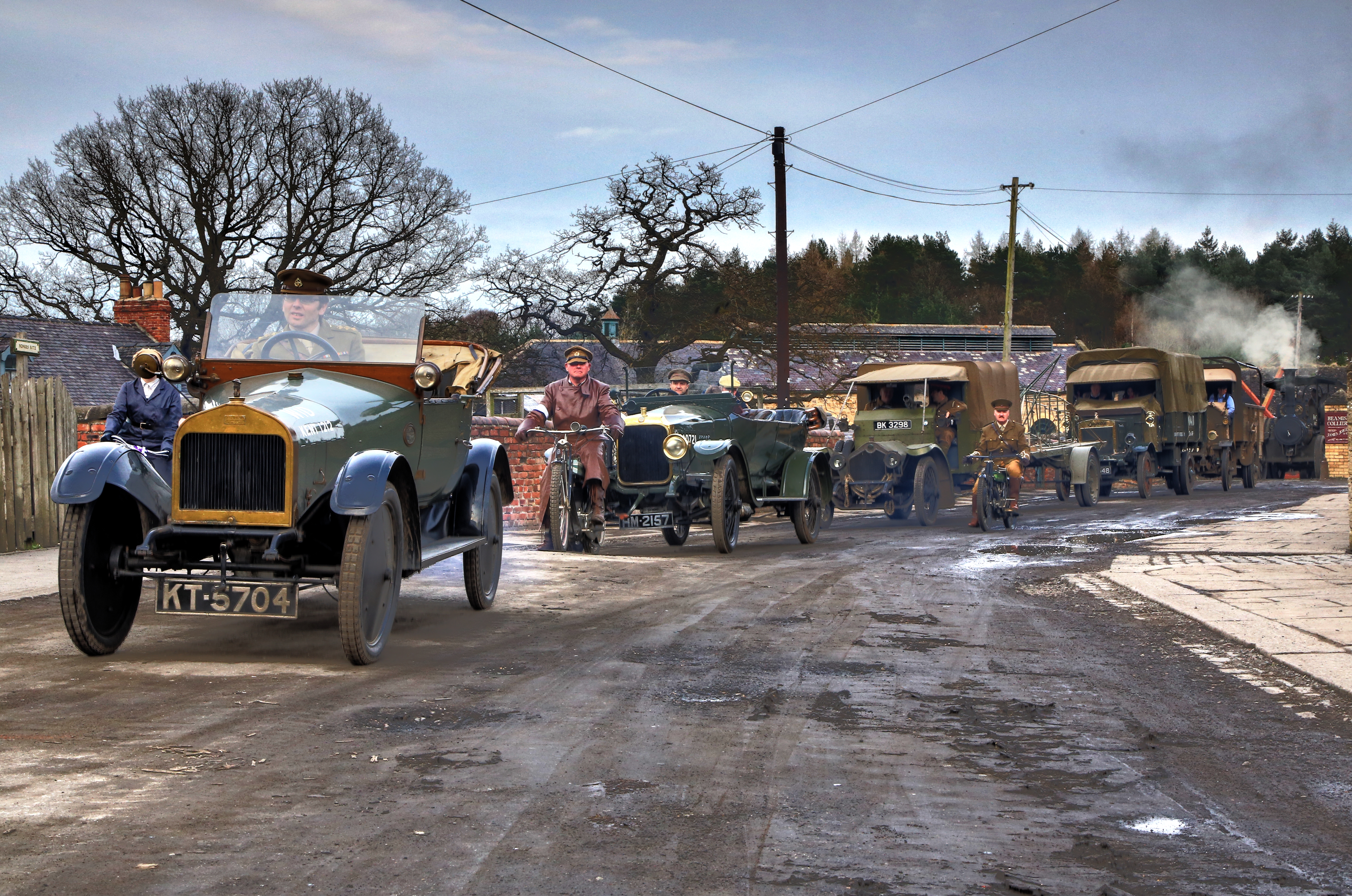
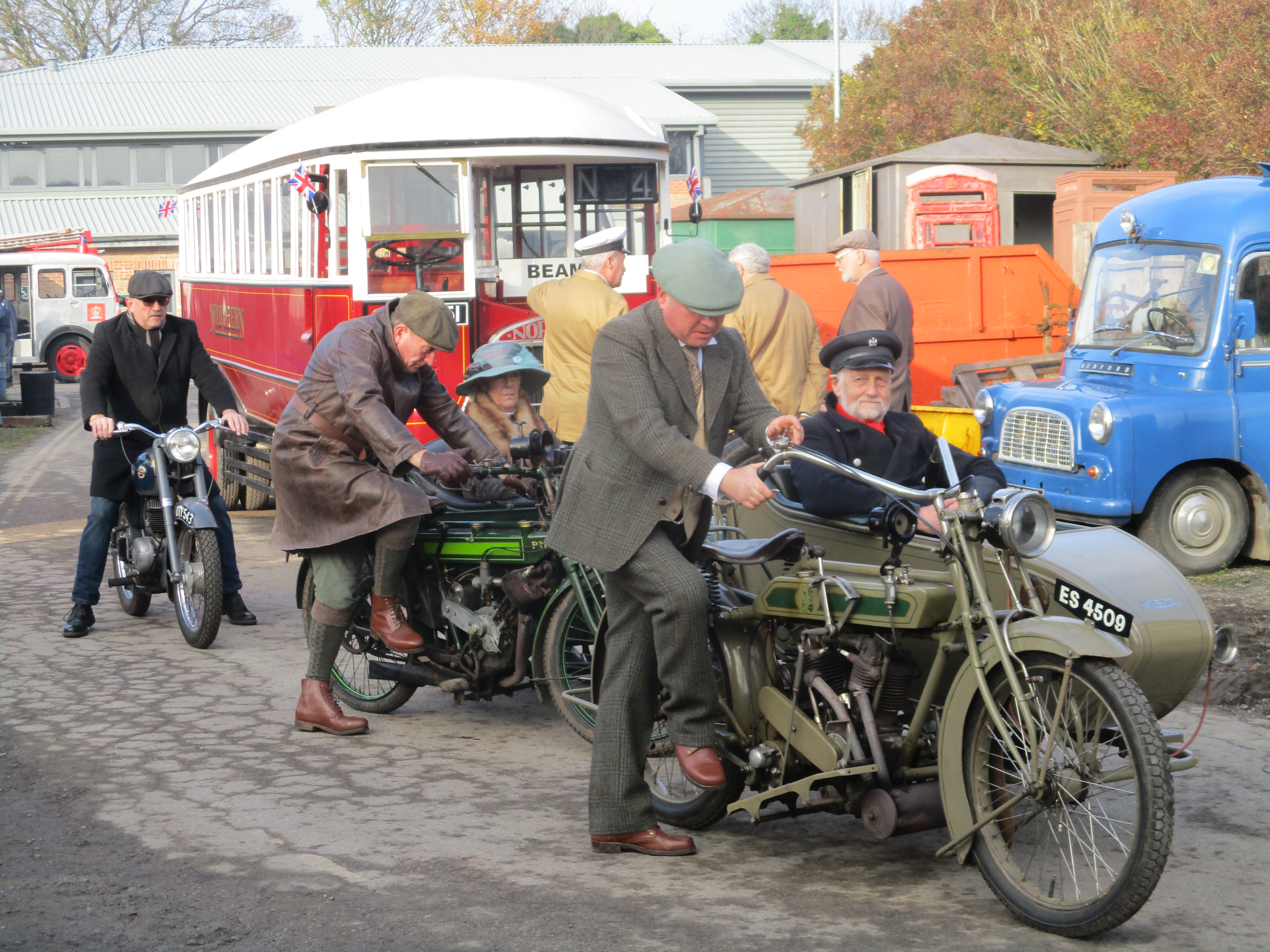
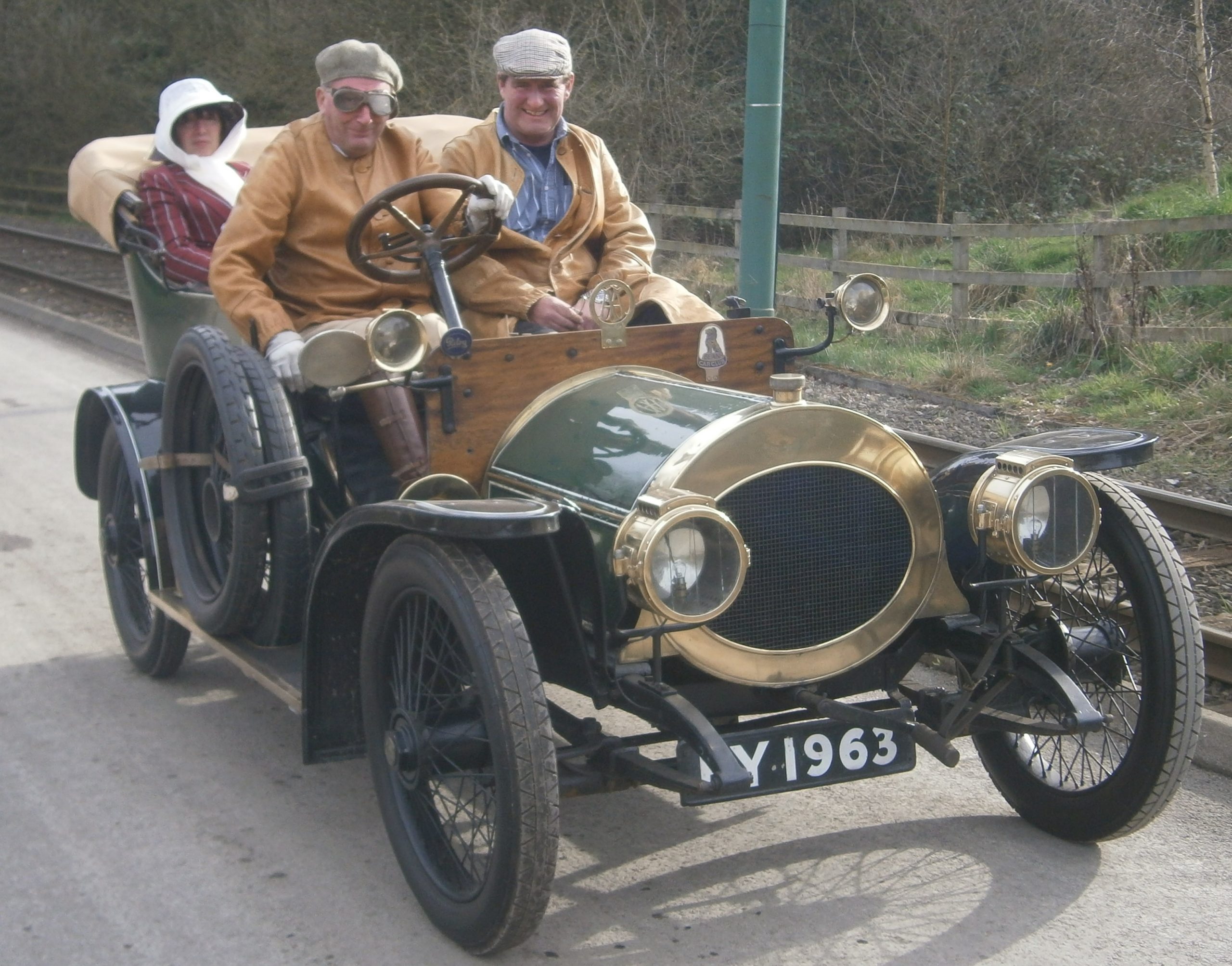
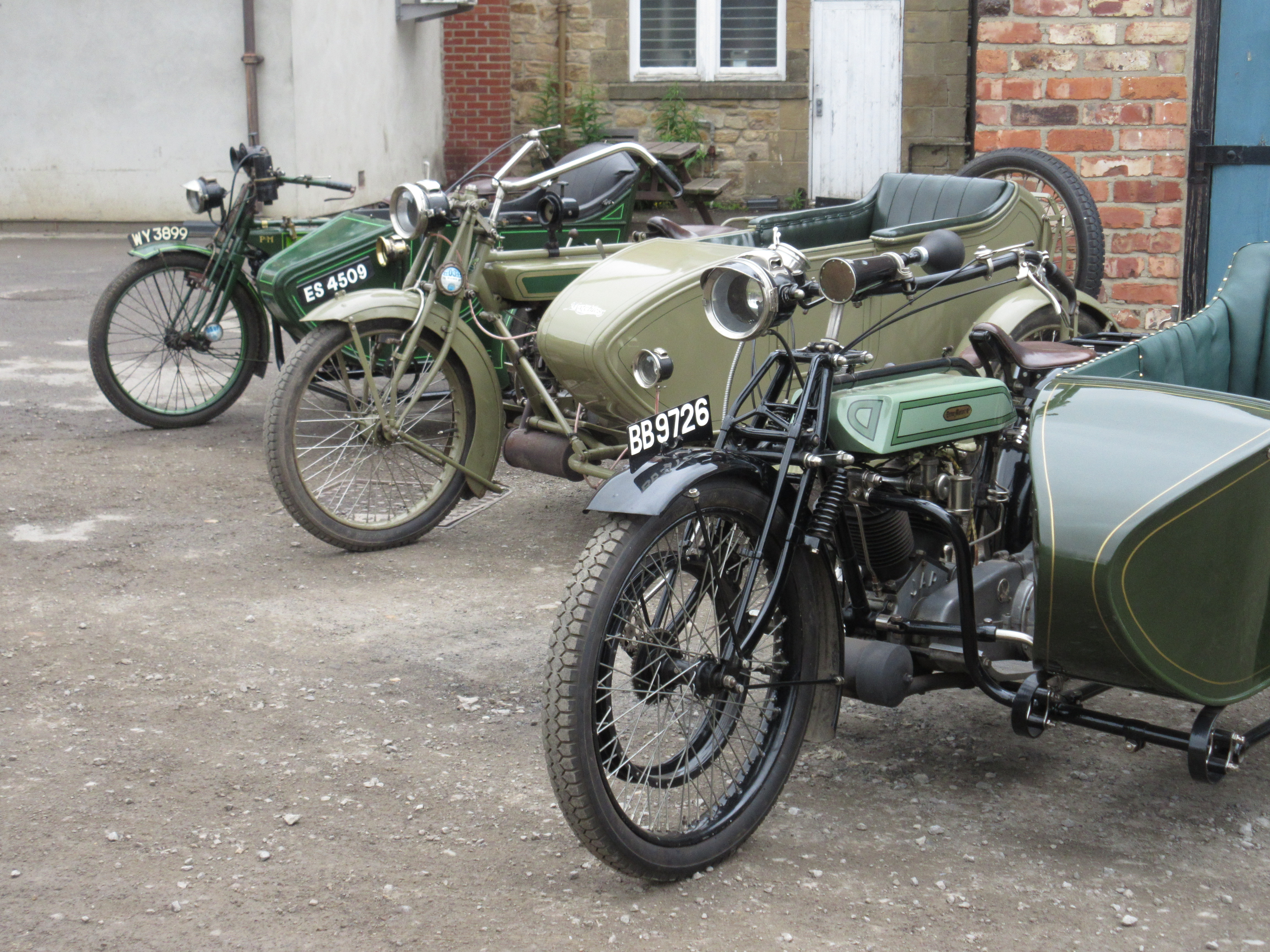
Some of the vehicles that visitors can enjoy seeing (and hearing!) operating around the museum have been fully restored from very poor and incomplete condition. The skills of the volunteers who have restored them are clearly evident in the results, so we conclude this feature with a small gallery of photographs showing them out and running around the site.


I am very pleased to receive the bulletins and the work people have gone to.
This one answered some questions that I didn’t know about so helpful in detail.
Keep up the good work and hope the year is a good one.
Dave