Dunrobin Developments 6
12th September 2011
Below: The final stage of Dunrobin’s exploratory work is now all but complete with the inner firebox having been removed last week. This is now being cleaned up to enable thorough inspection which is due to take place later this month. I am presently writing a Conservation Management Plan and preparing tender documents as, this being a significant capital project, we will have to work through the channels laid down by Sunderland Council for procurement of such work. The first stage of this, a Pre-Qualification-Questionnaire, has been completed (a PQQ being a scoping document prepared for us to determine the suitability of potential contractors, it is not the tendering document which is a separate and later stage in the process and will deal with the locomotive specifically). We have received board support for the project so I hope to begin the next stage of the paperwork process later this month. Meanwhile a site inspection is due on Wednesday to view what has been revealed by this latest stage of dismantling…
Latest Photos following visit…
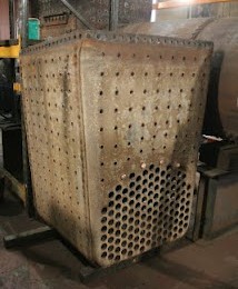
Below: The upturned inner firebox following removal. Clearly visible are all the threaded holes into which the stays are screwed. The lower half of the side facing the camera reveals the tube nest.

Below: Dunrobin’s boiler, inverted, to enable removal of the inner box.

Below: The foundation ring, which is located at the base of the firebox between the inner and outer boxes.

Below: These are the six girder stays which are fitted to the top of the inner firebox (crown) and which provide stiffness against the downward pressure inside the boiler. These are probably cast and are considered life expired. The one nearest the camera has been cleaned up for inspection.

Below: A view inside the boiler barrel. This is looking from the front (where the tubeplate has been removed) and the cavity to the rear where the inner firebox has been withdrawn is readily apparent, likewise the firehole door and removed stays through which the light can be seen. In the bottom (but actually the top of the boiler!) are the longitudinal stays, which do exactly what their description suggests, the copper take off pipes to the dome (where steam is collected at the highest point of the boiler for items such as blower, injector steam supply etc.) and the feed water delivery pipes from the injectors, which come from the backhead (where the injectors are located) and deliver cold water to the coolest part of the boiler (i.e. furthest away from the firebox) to reduce the thermal shock of delivering water at less than boiler temperature (though remember the water is hot from the process by which it is delivered using live steam).


Great to see ‘Dunrobin’s’ boiler disassembled and under expert review for rebuild, or replacement?
We once took the steam dome cover off, heavy, and looked at the throttle valve and down inside.
Here is another ‘Dunrobin’ adventure from 15 or so years ago.
I was not working on the footplate that day, but, was cleaning up the larger locomotive shop nearby.
That morning the Engineer ( Driver ) and the Fireman had cleaned out the ashes and clinker in the firebox left from the day before, emptied the cinders from the smoke box floor and the clumsy sharp-edged netting device around the exhaust nozzle and had then lit the fire to make steam for the day’s runs.
Coal was taken at night.
They were polishing the boiler jacket and tanks, cleaning the windows and adding valve and lubricating oil to the various oil location.
Those Vee-shaped oil trays under the front of the boiler ahead of the water tanks were definitely ‘Mickey Mouse’ and collected water, too.
Anyway, it was known that the right-hand boiler blow down valve above the mud ring would stick open, and it was not to be used.
( Should have been wired closed, in hindsight. )
What ever can go wrong, will.
Someone forgot, and opened the right blow down at 150 PSI steam pressure.
( There was idle talk to reduce the operating boiler pressure to 120 PSI and adjust the opening pressures concomitantly on the two safety valves, but, that would have affected the air pressure able to be produced by the single-stage Westinghouse air pump for the 6ET engine and train air brakes.
‘Dunrobin’ would not have been able to pull to the summit with the 1954 8-wheel British coach on 2.5 % at 120 PSI. )
The blow down valve stuck open.
I heard this sustained ROAR of escaping steam and could visualize the water level going down, down, down inexorably in the glasses with a hot fire burning.
I dashed over and found the Fireman in the cab frantically tryig to pull the fire out onto the deck, as the grates were not of the dumping type.
( Years ago, ‘Dunrobin’ had had a wooden-grate-type floor atop the metal deck, but, it was burned up by pulling hot coals and clinker out thru the firedoor.
That jagged hole, ouch!, in the deck had been drilled out years before to get at the top of the centre pin on the rear truck.
Those small copper pipes to carry oil the swiviling surfaces of the top of the rear truck are very floppy, and I would use the oiler from time to time to oil the top surface of the rear truck where it rotated in track curves. )
The Fireman managed to remove some of the burning coal from the firebox and we hosed it down on the deck. We then, the water now gone down from sight in the glasses, carefully aimed the water hose into the firebox to quench the fire left, trying to not get the cold water on the side or end firebox sheets, figuring it better to take a chance with the hose than to let the firebox sheets and crownsheet get too hot.
The blowdown roared on, and on, and on until all the water in the boiler was gone.
Then Silence reigned.
‘Dunrobin’ still lived, and so did we.
Later, two ball valves with pipe plugs on chains were applied, one on each blowdown, the plugs inserted to prevent an incident if some curious George opened the valve while under steam, the pressure would blow out past the cotters thru the plug bodies and indicate there was pressure.
Poor ‘Dunrobin’, survived it’s use and abuse in the ‘Dominions’, to return home to loving care once again.
Thank You.