
Samson’s crankshaft…
Work on Samson has seen a major accomplishment over the last week, with David trial fitting the new crankshaft and then spending a great deal of time on making it fit correctly and rotate smoothly. He had promised this by Christmas, and so, the project might now be seen to be ahead of schedule!!! We have also had some very good news from a supporter of the project, who has very kindly offered to take our coupled wheel centre castings and turn these into fully machined and tyred wheelsets, fitted to axles and complete with crankpins. The final two wheels are being cast this week and David has completed the axlebox pattern – this will be cast over the winter and will be machined to fit the wheelsets upon their return – a very exciting step and one for which we are immensely grateful to our supporter for. Thought is also being given to the gears and how these will be produced. Meanwhile, Graham Morris has a commission for the boiler design and hopes to progress this over the coming months. There is still a very long way to go, but these are fantastic milestones – we would love to have the wheeled chassis on display at next year’s Great North Festival of Transport – this being the first anniversary of the arrival of the frame plates and the commencement of the build itself.
The work on the crankshaft has been a complex and time consuming one, but as this sequence of photographs show, the result is certainly impressive and very pleasing to gaze at – the engine seems quite real now.
Below: A couple of views showing the first trial fitting of the crankshaft into the pedestal bearings. This was a major step in the project and revealed relatively little fettling to be required. The left hand side bracket has two bolts in place to locate it accurately, enabling the shaft and second pedestal to be set up around this.


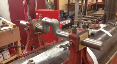
Below: A close up of the bearings, pedestal and cap – to which a lubricator will be fitted. The caps are lock-nutted and also pinned to ensure they stay put. Note the collar against the ‘brass’ – shrunk into position and then machined, this, and a corresponding collar on the other side, provide a reaction against any lateral thrust on the crankshaft.

Below: With the crankshaft now positioned, Dave set about lining up the pump (mounted on the reverser/regulator stand). This will be driven from a third eccentric on the crankshaft, the drive rod being joggled to give the required alignment. The crankshaft, with the knuckles painted, certainly looks like a forged example and amply repays the vast amount of time spent by Dave on getting it to look right.


Below: A near-drivers eye view, clearly showing the reverser/pump/regulator pedestal in position.


Recent Comments