T&I News Week 42 2015…
Dare I say we’ve been very busy lately?! It seems to be a repetition that hardly need occur, but in recent weeks has been particularly true! So I apologise for lumping so much into one post, but hopefully it will bring readers up to date with activities within the Transport & Industry team. We also take a look at one of the less romantic jobs which is undertaken by the staff maintaining the heritage traction we perhaps take for granted at times but is such an important part of the ‘offer’ which sets Beamish apart.
RHEC
The travails of the Bedford CA gearbox were described last time. Further investigation revealed a number of additional factors within the gearbox itself which Alan and Chris set about repairing. This was assisted by the transference of the CA manual from a shelf in my office (where I’d forgotten about it after seeing it on eBay) to the workshop bench!
Below: Close inspection of the main gearbox shaft revealed that the roller bearing pins had collapsed, imprinting the shaft with their presence and causing a stiff spot in the rotation of the gearbox.

Below: A potentially alarming scene!

Below: Chris set the shaft up in the lathe, clocked it then dressed the journal face.

Below: A close up of the tidied journal.

Below: The journal was reduced in order to take a bush…

Below: Chris then parted the bush from its bar, ready to fit to the shaft.

Below: This was then pressed onto the shaft, returning the original outside diameter, sans imperfections/defects.

Below: Alan then reassembled the gearbox having carefully committed to memory (!) the exact location of each component. No problems here! The shaft was reassembled into the gearbox, as seen in the second and third views below.


Steam Locomotive Maintenance
Every one of our pressure systems (boilers) has to undergo an annual inspection – spaced on paper at 14 months but for convenience usually arranged every 12 months to coincide with the winter maintenance period. As well as the statutory work, it is a chance to carry out more intrusive maintenance, once such job being work to remedy the passing of steam around No.18’s regulator. Matt and Dave G set about stripping this – removing the whole valve to the workshop, as we shall see below.
Below: We begin with the complete regulator assembly, consisting of two valves, the mechanism for opening and closing them, a spring and the main steam pipe union, the regulator end of the pipe which carries steam from the regulator (in a controlled amount) to the valve chests and cylinders.

Below: A side view of the assembly, which normally stands such that the pipe entering from the right of this view is vertical. Steam is collected at the highest (i.e. driest) point of the boiler – usually within the dome or another raised chamber on the boiler. Regulators such as this are mounted within the dome (some are to be found in the smokebox) and control entry of steam into the main steam pipe. By placing them at the highest point, the risk of priming is mitigated (where water is lifted through the regulator and carried into the cylinders – water being incompressible this can cause extensive damage). No.18’s boiler design is actually such that priming is quite common – the high-topped firebox contributing to this tendency – it is not a well designed boiler! The tube nest is also such that the tubes are arranged in vertical rows, not alternate rows, so water surging or lifting is not interrupted by the tubes and can therefore find its way to the regulator valve.

Below: In this view the spring has been removed – this holds the pilot valve closed when no steam pressure is available to do the same – remember that the valve is within the steam space of the boiler and therefore subject to the applicable boiler pressure against the plates.

Below: When the regulator is opened, the pilot valve is the first section to move – an oblong slot enabling the link at the end of the regulator rod to move the pilot valve before the secondary (main) valve is collected by the link. The pilot valve is well worn and will be re-machined to ensure the valve faces close tightly against the face of the main valve.

Below: This is the secondary ‘main’ valve removed from the assembly (and which we anticipate renewing). It has also been inverted in this view. Note the oblong slot, which enables the link pin from the regulator rod to move the pilot valve before moving the secondary valve. The slots are the means by which steam passes from the boiler into the main steam pipe.

Below: The passing steam suffered by No.18 is almost certainly caused by the poor fit of the main valve to the valve face – which as can be seen here, is in poor condition and suffers numerous surface irregularities (an alternative cause could be a perforated main steam pipe – which is a major problem on any locomotive). This area was not tackled during the restoration as it was not believed to be cause of any problems in the brief 1970s operation and there was insufficient funding to do anything other than service this component in situ. This surface will require grinding and the slots which retain the valve will also be squared up as part of the work.

Below: Moving on to Locomotion No.1 – this has now been fully de-tubed and moved to the Colliery Engine Works for winter maintenance and re-tubing. Note the layout of the tube nest – particularly how each tube above or below its neighbour is not in vertical alignment. No.18’s are vertically aligned, creating tall vertical avenues for the water to surge through. Not desirable!

A day with Dave G
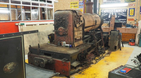
Below: Dave Grindley is our Steam Technician, carrying out the day to day maintenance on all of our steam locomotives and steam plant. One of his more unpleasant tasks is the cleaning of the Gallopers centre engine flue tube. As this engine does not have a conventional chimney, the gases (and draft for drawing the fire) are routed sideways into a box section flue, then into the centre column of the ride itself, passing upwards and out of the chimney at the very top. As a result of this indirect route, deposition of soot is quite pronounced. Add to this the exhaust steam from the centre and organ engines, which contains oil, and a sticky cocktail is the result. This can vastly impair the draft on the fire, the chimney becoming choked and also insulated against becoming hot (hot chimneys draw better), slowing the flow and further adding to the problem. In due course we aim to fit an oil trap on the steam exhaust side, but meanwhile the very unpleasant job of cleaning the flue falls to Dave at regular intervals. Once a year, with everything dismantled and under controlled conditions, the flue is ‘fired’ and the debris burned out and ejected out of the top!

Below: The view above shows the first section of flue, whilst the view below shows Dave rodding this out from ground level.


Below: A note entirely happy chap – and suspiciously clean! Within minutes the horrible glue like black soot will be attached to everything it can find to stick to.

Below: We are now looking into the vertical flue – the centre pole of the ride.

Below: The centre flue is accessed from within the centre rotating section of the ride on top of the centre truck (behind the engine) – Dave disappears into the shadows to carry out the rodding of the flue. This is also the way in which access to the gears which drive the cranks (on which the horses hang) is gained. Our ride works far harder now than it ever did, operating for so many days a year when compared to its original life travelling from show to show. As a result, accumulation of soot is perhaps inevitable, but this particular job does explain why a changeover to electric motor traction was favoured!

Glyder strip starts…
Below: Graham Morris was in the area so made a start stripping his Barclay o-4-0WT ‘Glyder’ – a project we will get stuck into once the preparation for the Christmas festival has been completed and Matt and I can dedicate a bit more of our time to the project. A number of other narrow gauge projects are also in the offing, once Samson is complete, the FR granite waggons are progressing and we have a bit more track laid in the Colliery…


N&G 49 Progress
Below: Two views showing the interior of No.49, the Newcastle & Gosforth horse tram that a team of volunteers are restoring. They are currently concentrating on the interior of the lower saloon – gallons of varnish being applied!


Christmas is coming…
Below: It seems to happen sooner and sooner each year doesn’t it?! Christmas at Beamish begins on the 14th November, preceded by the opening of St Helens Church, half term, a number of Halloween evenings and a couple of bonfire nights. For the grottos (at the Waggonway) a new frieze is being created showing a seasonal scene (of Georgian vintage). Sarah Jarman is carrying out this work, amongst the varied painting projects in the Finishing Shop – I had hopes of a spacious progression for Samson – no such luck on this painting front yet!!!

Outside Works
Below: It is possible the novelty of the hired in ‘big yellow machines’ is wearing off for Darren and Mark, who have tackled the enormous job of preparing the ground for a new collections storage barn at the north west part of the site, well beyond the usual public areas of the Museum. The have removed a huge mound of earth, then carried on downwards. This is being back-filled with stone, to provide a stable base for the new building and its concrete floor. It has opened up a temporary new view of the Regional Museum Store building from the western end. This ‘enabling’ work will be completed this week, enabling the barn builders to start work next week. All that soil had to go somewhere, and the next job for the big machine is tidying up the arisings in various locations they have been tipped in.


Site Moves
Below: Locomotion No.1 has moved from the Waggonway to the Colliery for winter maintenance – including re-tubing (as we saw earlier, the tubes have now been removed).

Below: Locomotion is seen inside the engine shed – No.18 and No.1 have also been stripped for their annual boiler inspections. Note No.18’s dome cover removed – to release the regulator (seen above).

Below: We also saw the departure of ‘William Finlay’ a 3′ 2.25″ Fletcher Jennings locomotive that had been in store in a hidden location at Beamish for several years. It is now in Lancashire for cosmetic restoration following sale to the Narrow Gauge Museum Trust, its ultimate destination being their museum at Tywyn in Mid-Wales.


Recent Comments