
Transport & Engineering Diary December 2025
Here is some light Christmas reading, in the form of an extended post for December…
Where did 2025 go?! We reach the December post with plenty taking place and hopefully still an enjoyable and informative read for blog followers. This is rather a long post, and normally I’d split this length of post into two, across the month. But with Christmas holidays looming, it would have meant a long post then quite a short one – and I’m sure this will be of little consequence to those reading it anyway. That said, as the post has evolved, I might have separated out the Samson news update into a separate post.
I do tag the themes within each post, which makes it more appealing to search engines, and it is always interesting to see where ‘Beamish Transport Online’ pops up when I’m looking for other things!
I have prepared an end of year review, with a look ahead to 2026, as has become traditional on here, though I don’t think I’ll have time to write any articles in time for the holiday period. I am working on a new guide to the transport collection, probably in two-parts, and am also trying to keep a little of my powder dry in terms of potential contents for this as it is becoming a work of increasing magnitude – but hopefully once written and published, it will serve its purpose for very many years to come.
Rowley Station
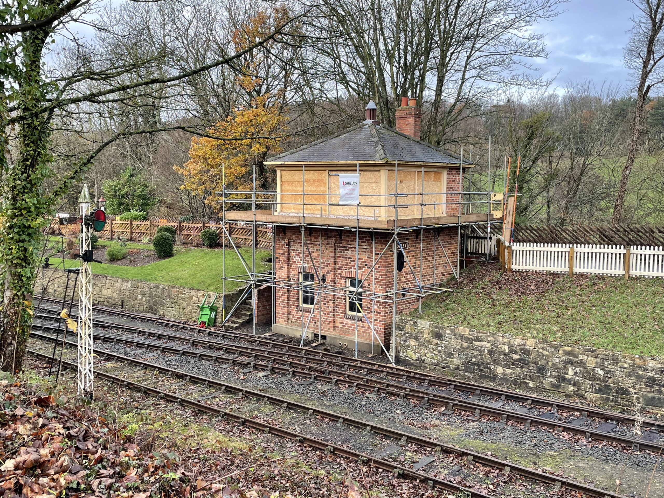
Below: The sliding windows from the signalbox have now been removed for repair/renewal. The effect of the boarded up apertures is rather gloomy, but the result will be worthwhile as this building is something of a focal point for the station and view from the Town.
Samson
Work is underway on Samson’s retube, which is being carried out by Matt Ellis and some of his colleagues in their spare time at the Ffestiniog & Welsh Highland Railway works at Boston Lodge. Blog readers will recall that Matt was the Keeper of Transport at Beamish for several years before moving to the F&WHR to take on the role of Operations Manager. He has sent some detailed reports back on progress, so I’ll hand over to Matt for the update on Samson:
Below: With the locomotive being partially dismantled to gain access to the the first round of stored bits. The intention is to clean as much as we can when it’s removed then Vaseline/oil/grease to protect, then assembly is a nice job!
Below: Tube removal – the method of extraction was to grind the firebox end flush with the tube plate. This end is 1/16″ smaller in diameter than the front, but the section that protrudes into the firebox would damage the tube plate if dragged through it. The tube ends were then heated to orange, thus expanding them within the constraint of the tube hole. When they cool, they are then loose in the tube plate. A puller is then used to draw the tubes forwards and with the firebox end being smaller, out through the front tube plate. The first three were extracted with this method, but took a long time and a great deal of effort. It also required the puller to be rebuilt for every tube.
Below: The cause of the difficulty in extraction – the front end expanding appears to have been done with a very long expander, resulting in the area immediately inside the front tube plate being larger than the hole. Even with repeated heatings it was going to be an ordeal to get them out. Fortunately the loco has that manhole in the top of the front tube plate. Method two, was somewhat more destructive but also proved to be much quicker. The gas cutting gear was used, through this manhole, to cut each tube in two, the firebox portion was then barred to the side, and wiggled out of the firebox tube plate, then dropped in the boiler. The front portion was then folded in with the air chisel, and also knocked into the boiler. The debris can then be fished out through the manhole.
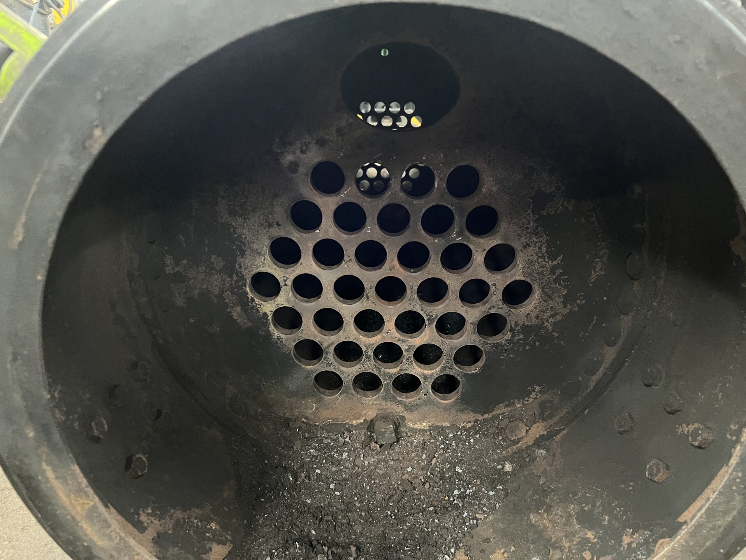
Below: The bare tube nest. The manhole referred to earlier can be seen above the tube nest. The boiler was now ready for vacuuming out of debris and then a final washout with water.
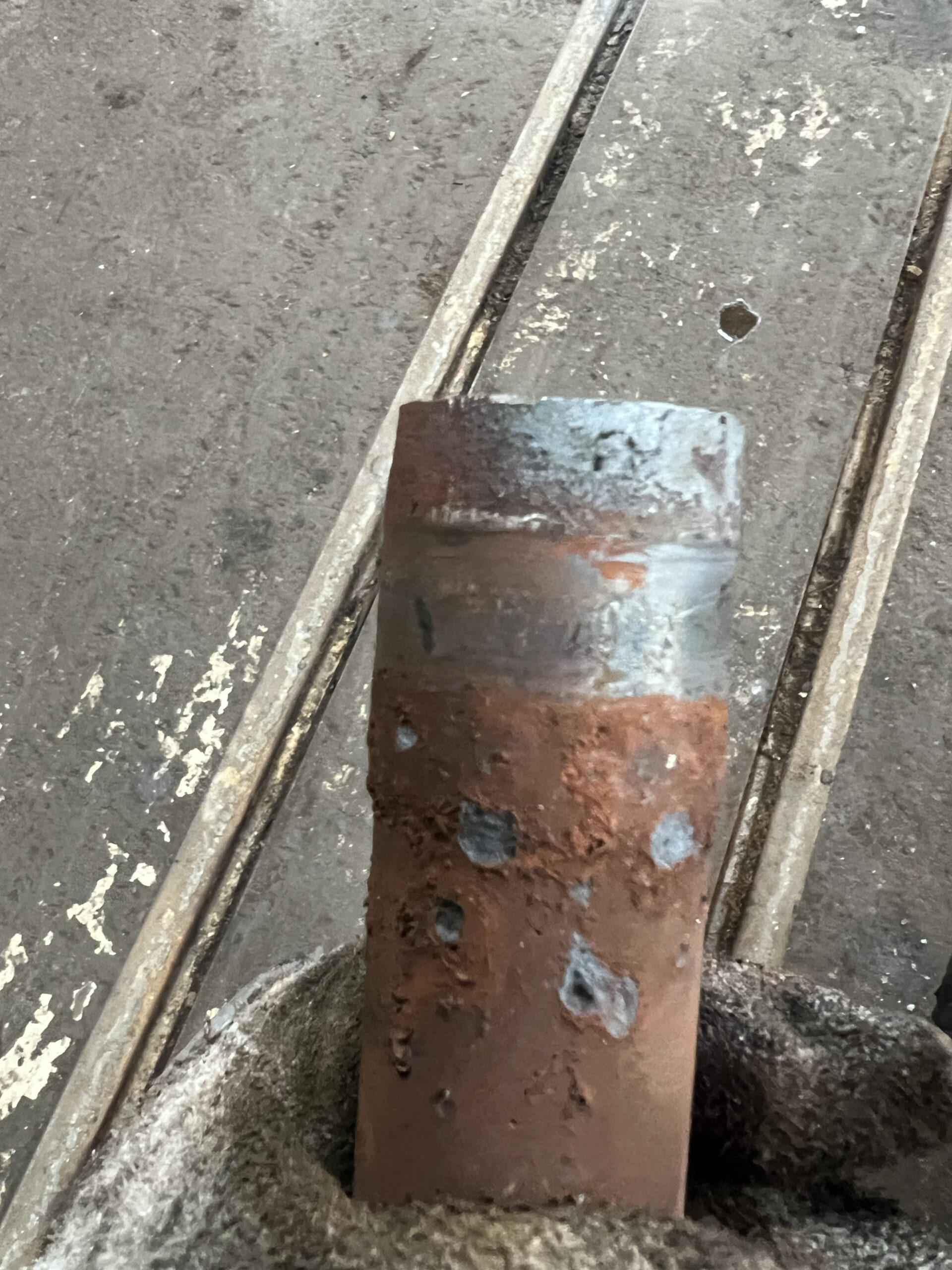
Below: This view shows the expansion described above – the section of expended tube shouldn’t protrude into the water space, indicated here by the red rust section of tube, but it clearly has bellied out – and this made extraction through the tube holes very difficult. Whence method 2 being adopted for removal.
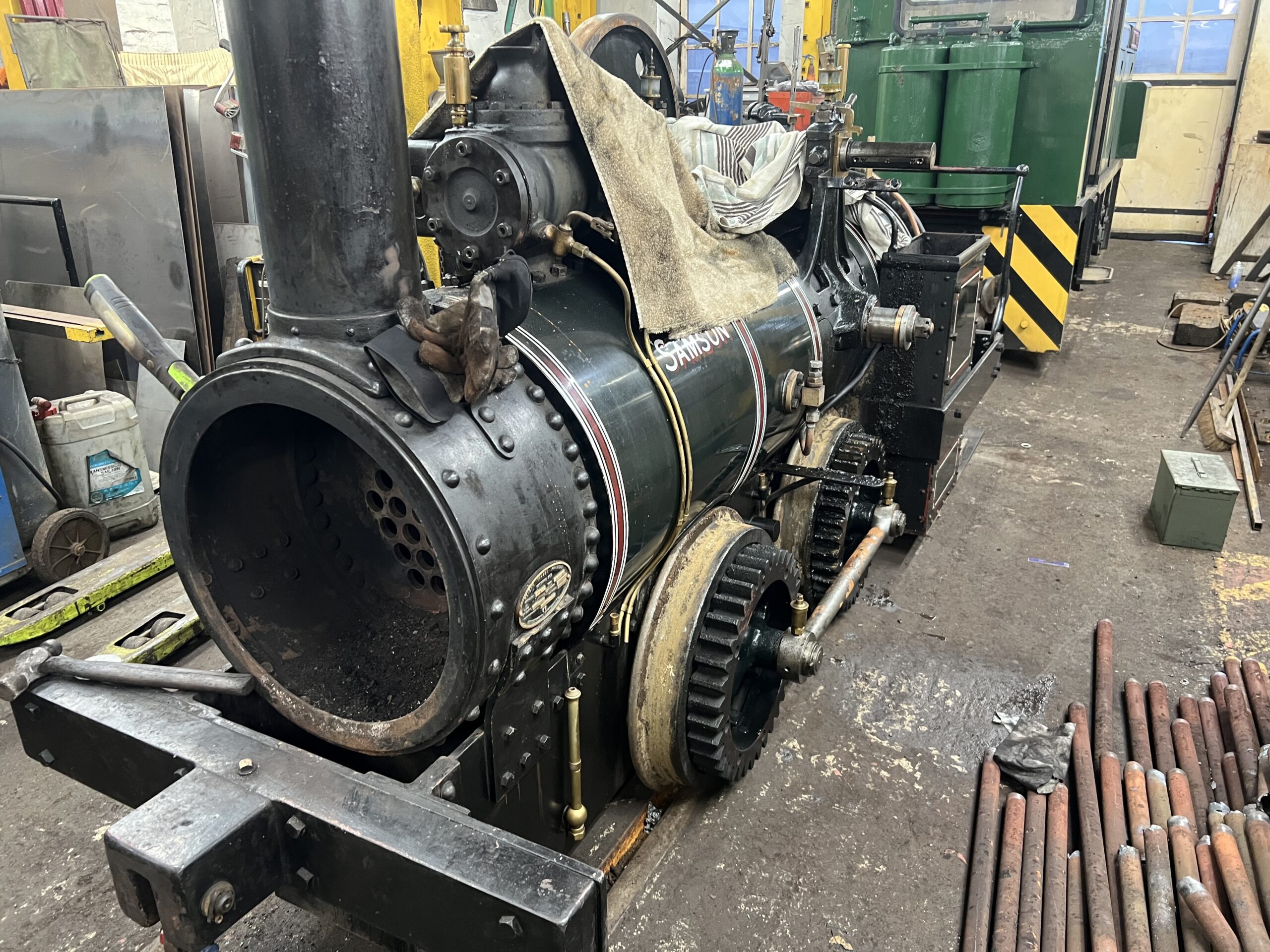
Below: The top end of the loco is also being partially dismantled. All of the motion (valve gear) has been removed. The gear guard and drive gears are off, to aid removal of crank and then cladding. All the motion has been polished and greased for storage, whilst the crank, connecting rod and crosshead will be in receipt of some attention as part of this overhaul.
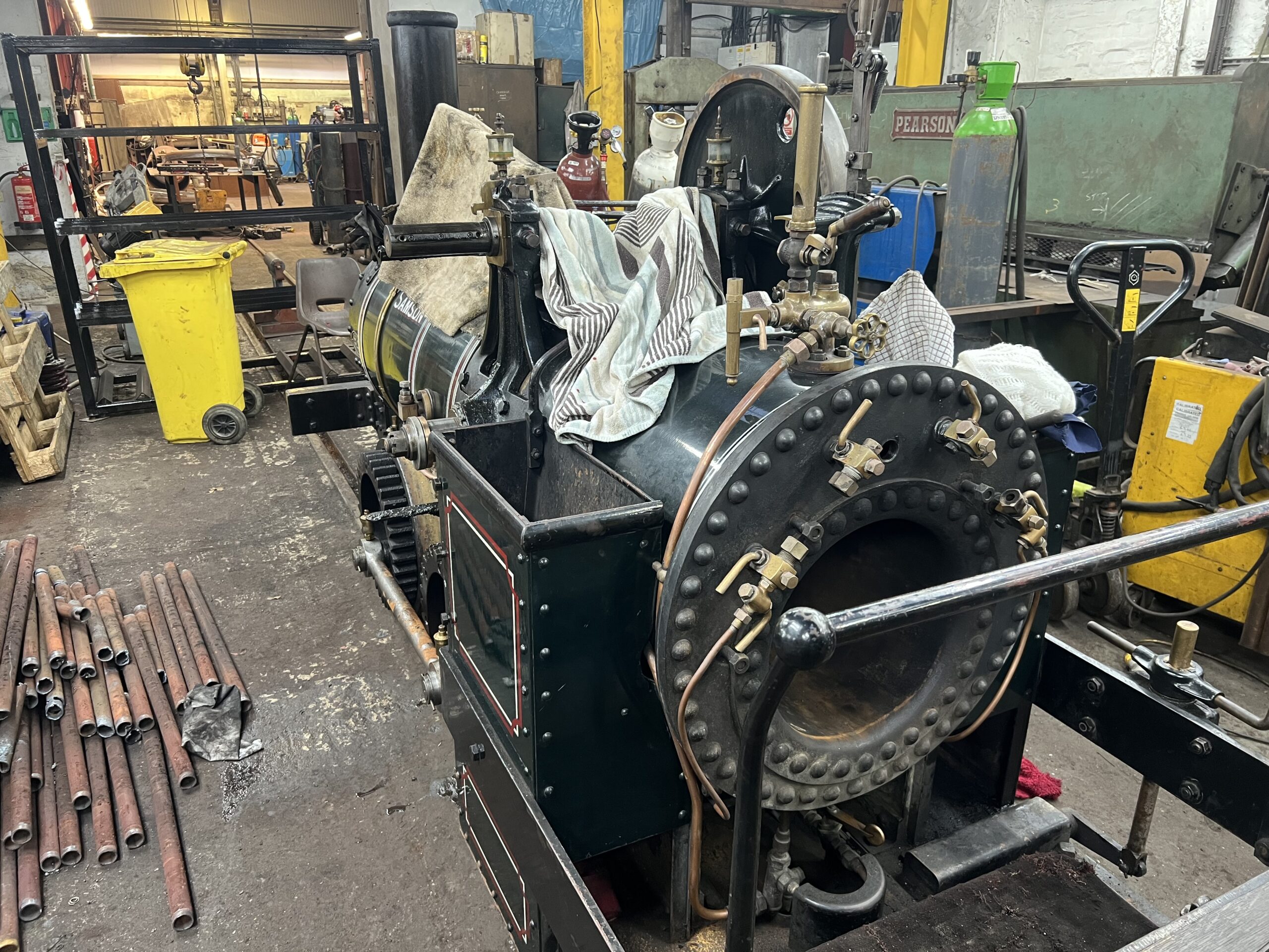
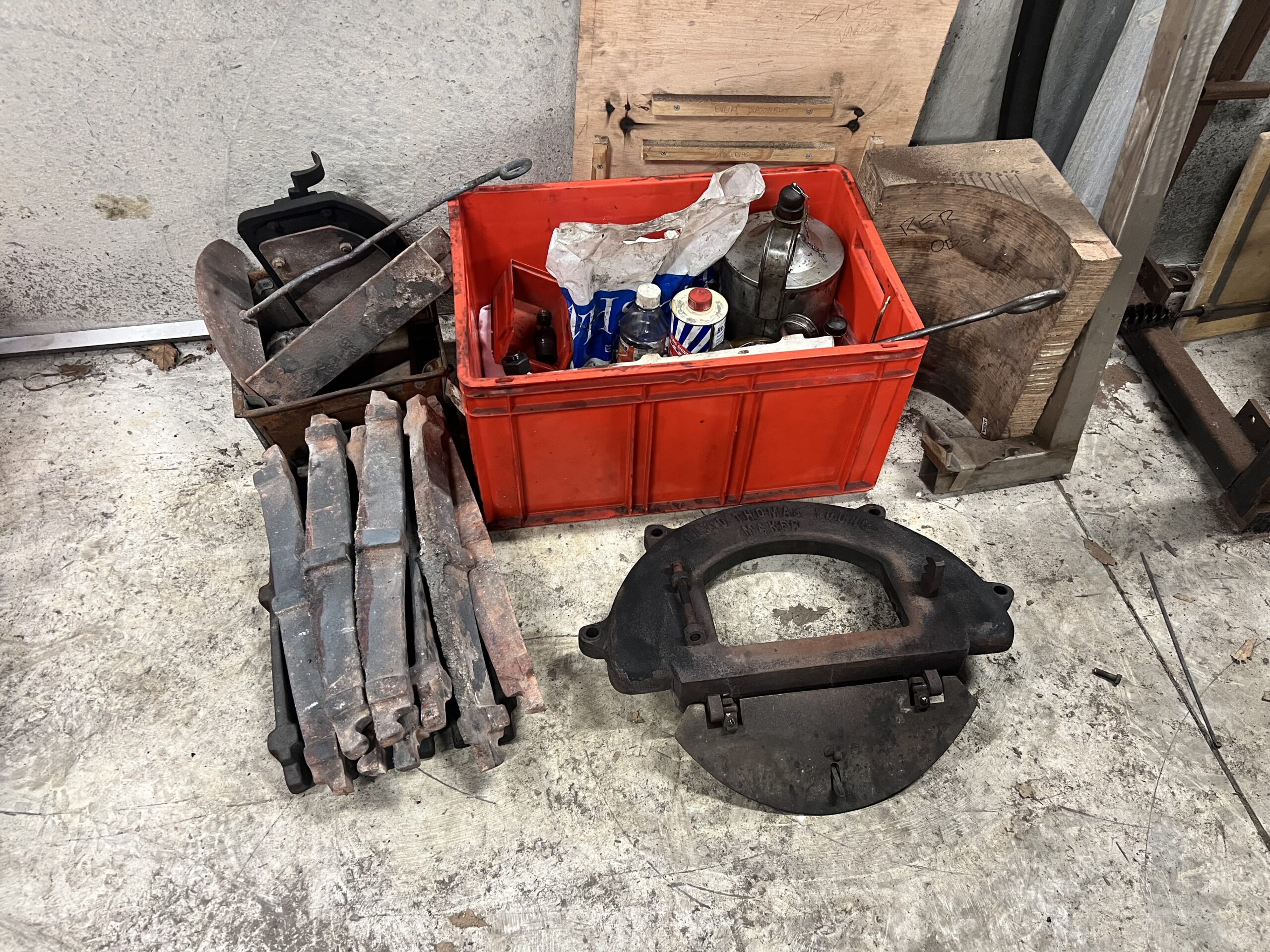
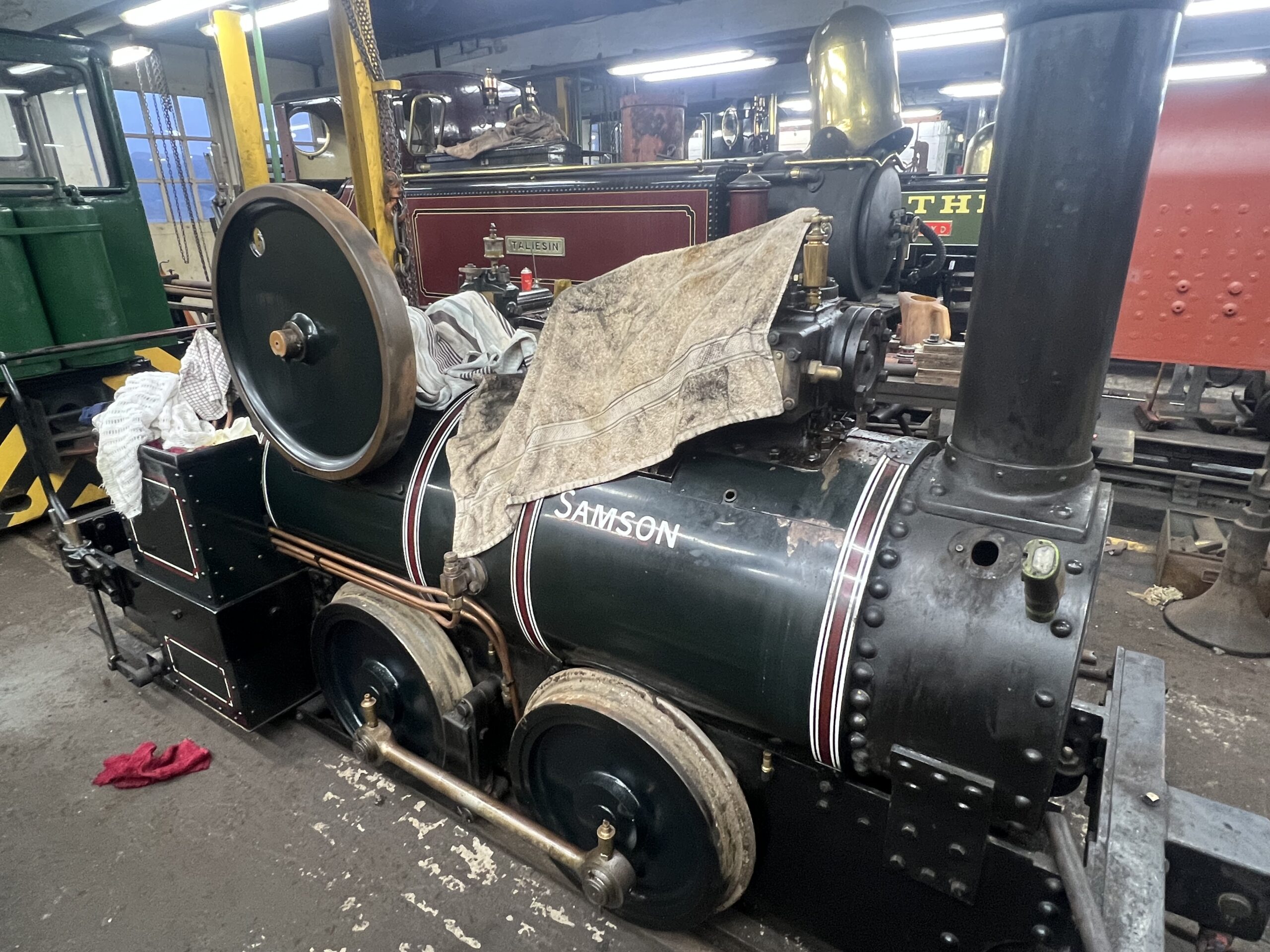
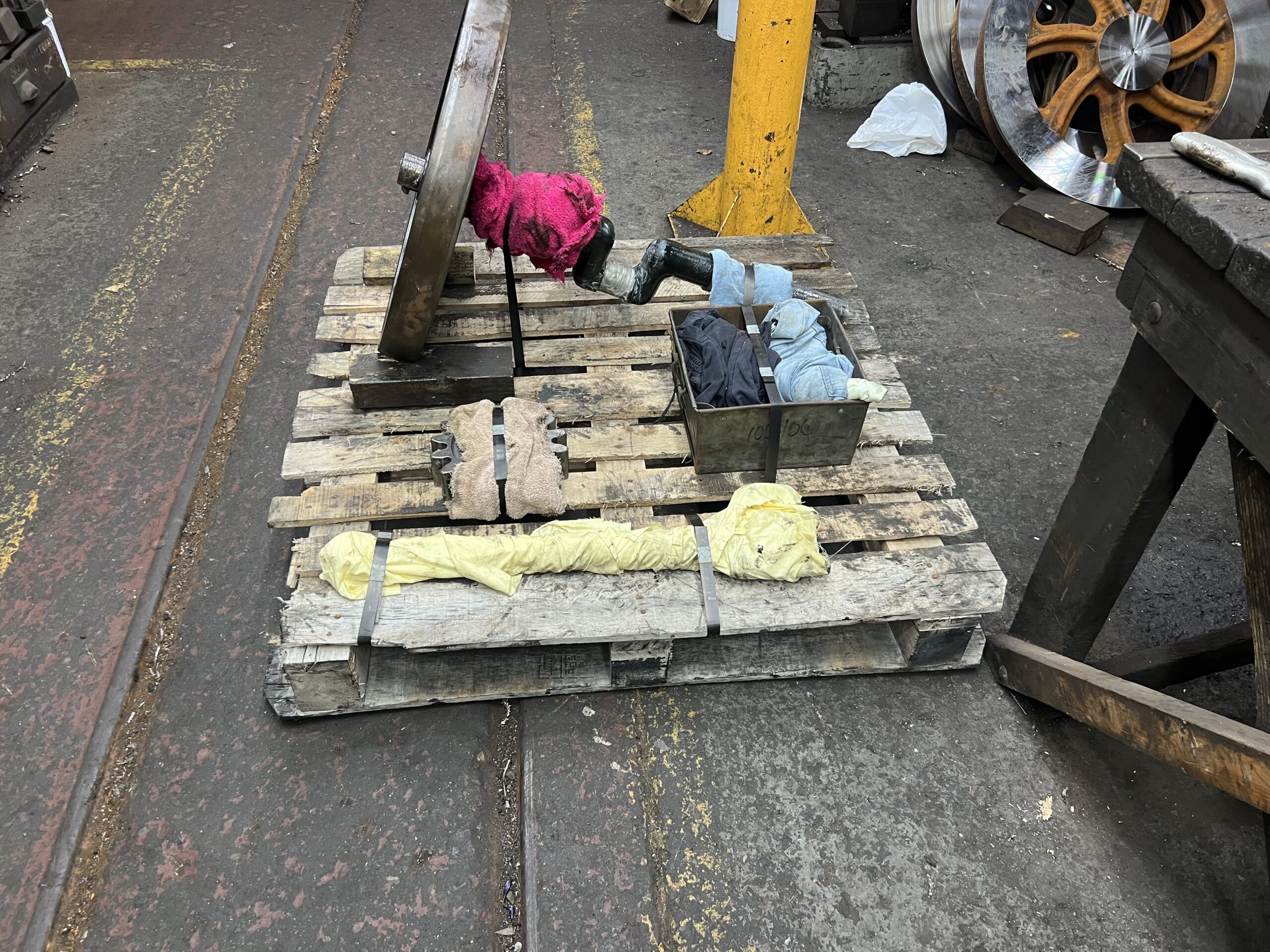
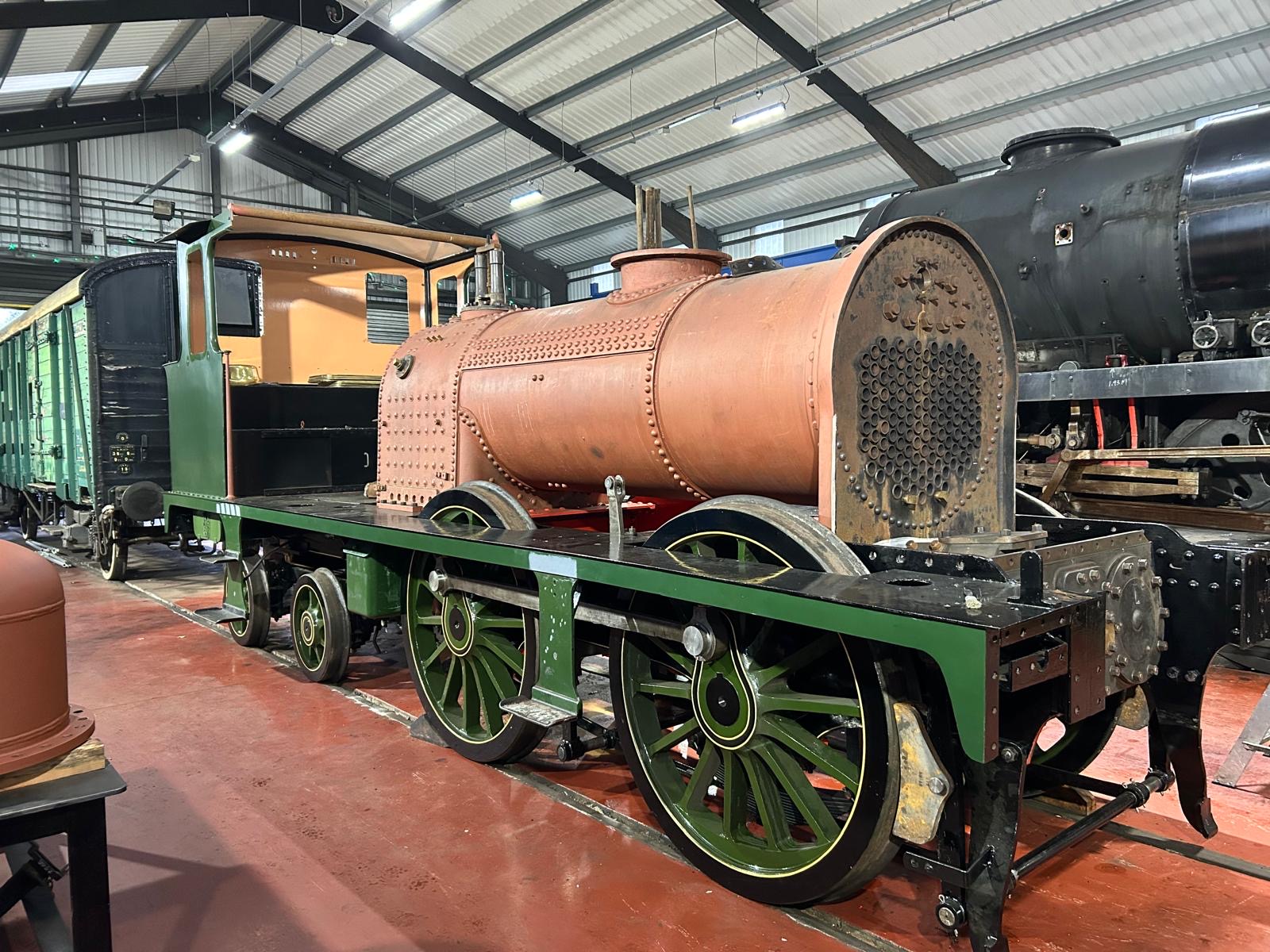
Below: Samson keeping some interesting company this winter.
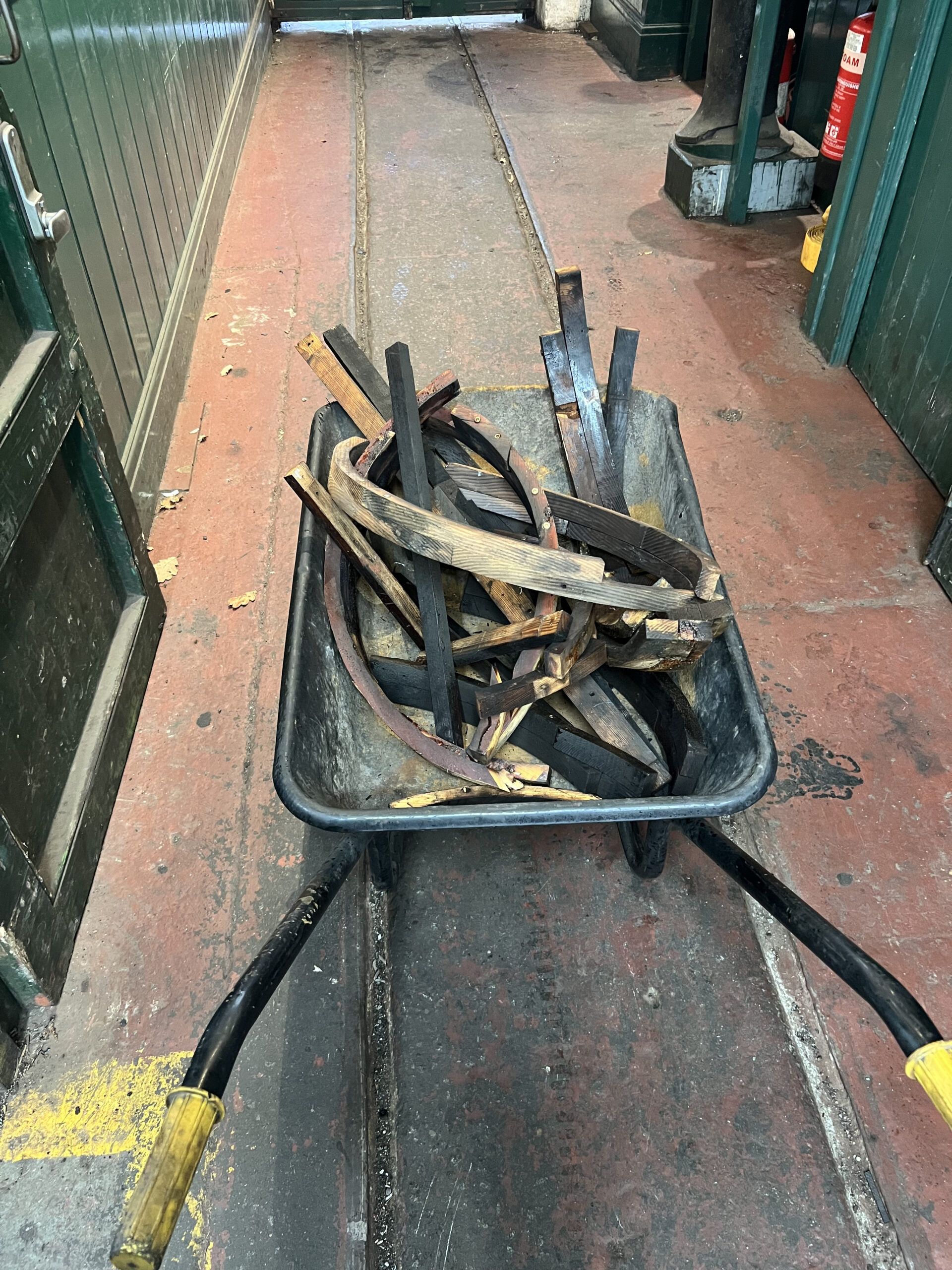
Below: After another session of dismantling – this is the barrow full of wooden cladding spacers after removal. These cannot be re-used so new wooden lagging will be made when the boiler is reassembled.
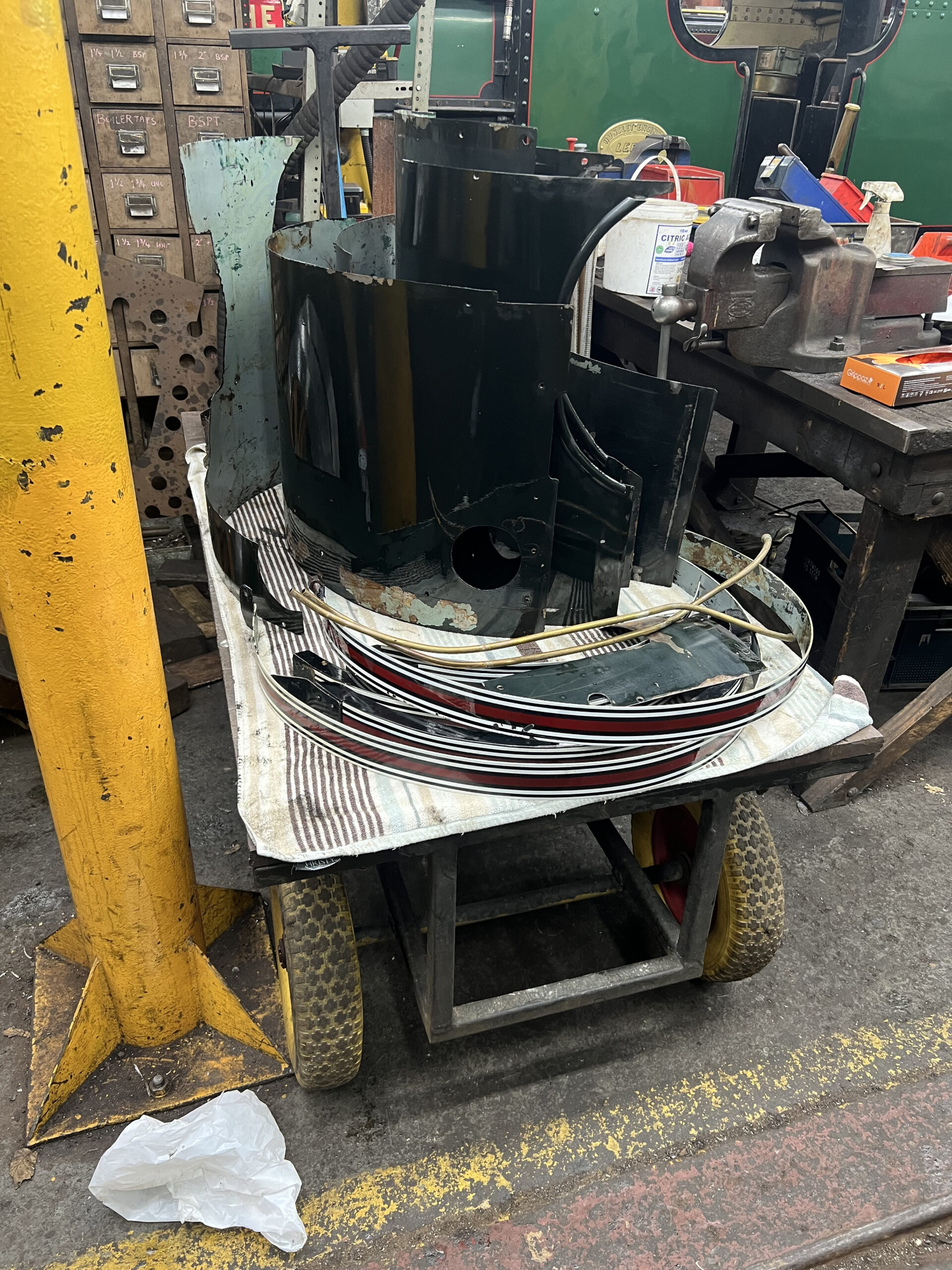
Below: The cladding sheets after removal – these will be tidied up for future refitting.
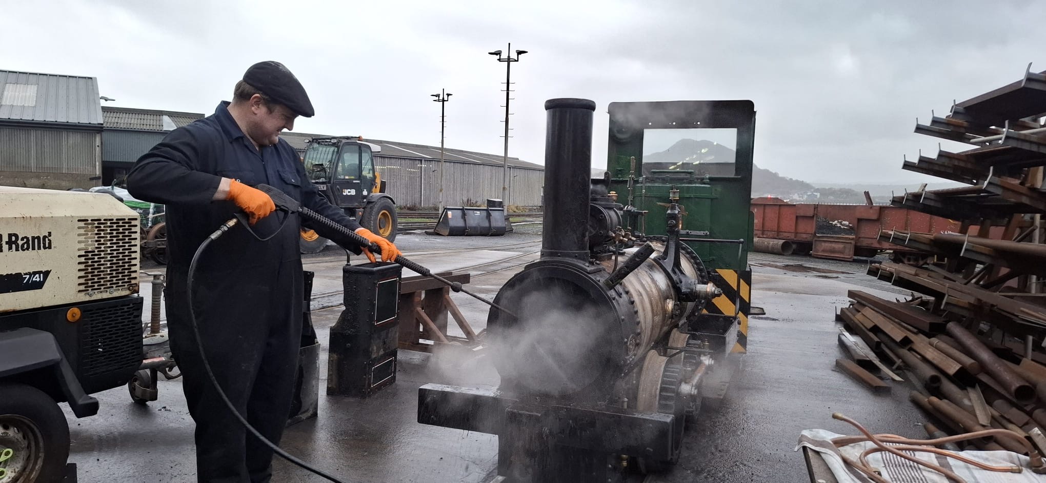
Below: The boiler was washed out again then the bunkers and the footplating (hidden faces) steam cleaned.
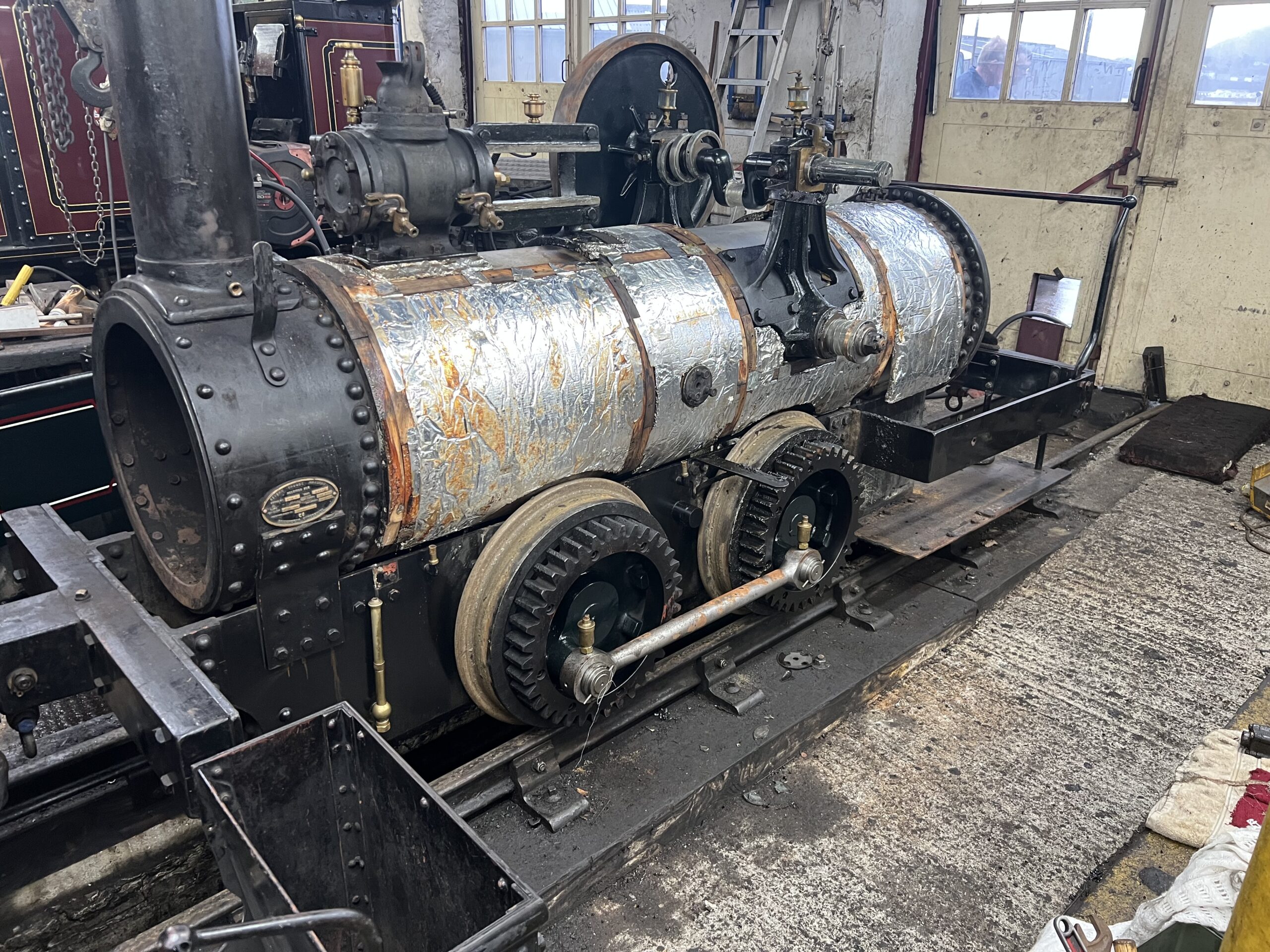
Below: The cladding sheets removed. Lagging to come off next.
Below: The bare shell. The bunkers are off but footplate has been reassembled to aid shunting.
Below: All of the cladding parts were degreased once removed. Those behind the gears and bunkers were quite well covered in oil and muck.
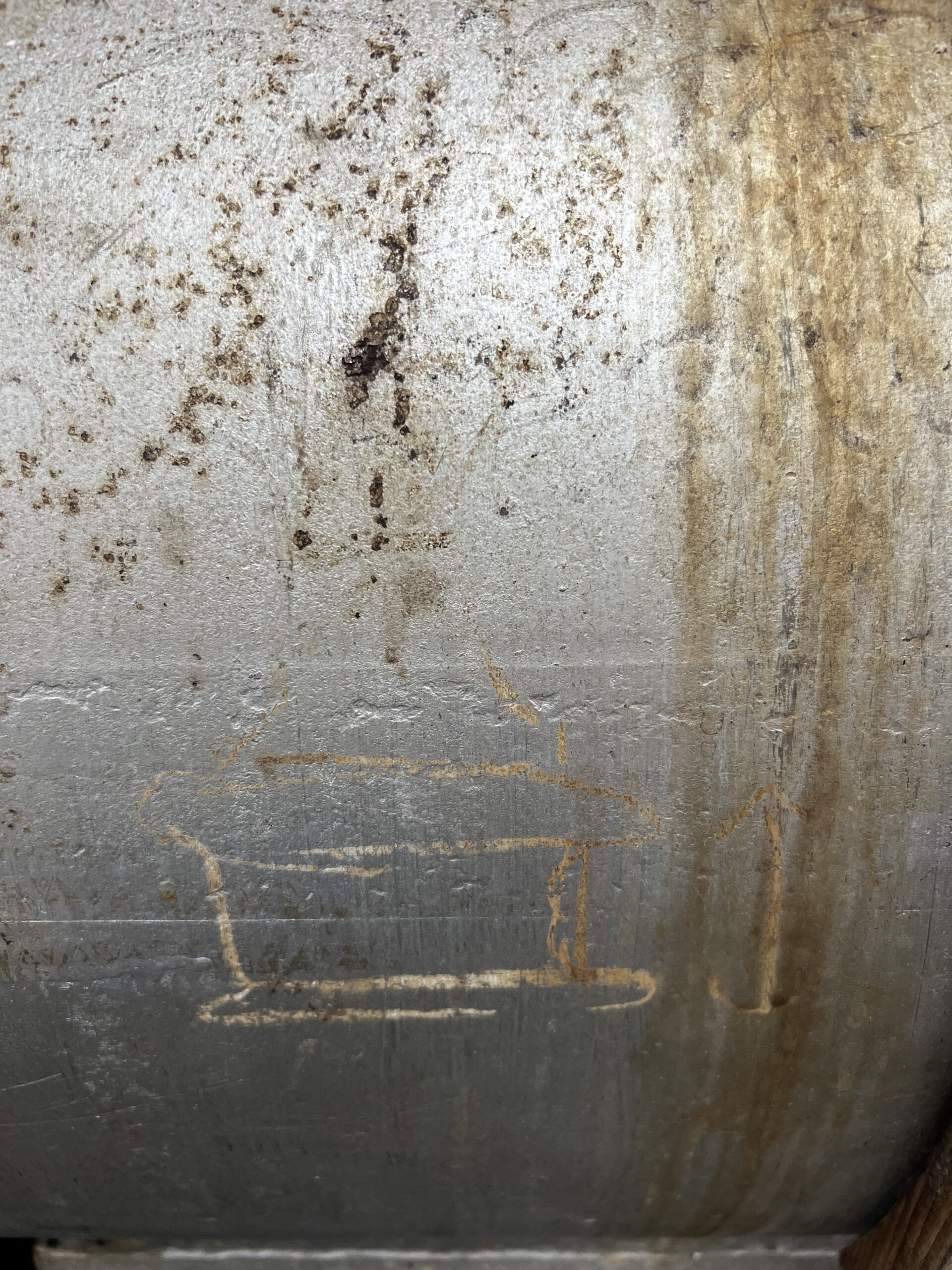
Below: Samson archeology… I remember Paul drawing this! It’s a chalk sketch of the (then proposed) cast safety valve bonnet for the rear safety valve.
Below: A pallet of bits heading back to Beamish for attention, including the crosshead and sliding gear keyways on the crankshaft. The flywheel has become loose on the crankshaft, despite repeated righting of the key, and the keys that the sliding pinion gear have also moved and started to jam when this feature is used. The crankshaft will be modified to allow a nut to be made that will secure the flywheel to the shaft. Additionally, the piston rod is secured only with a cotter, and the crosshead will be modified and a new piston rod made with a screw thread to create additional security for this in the crosshead. I’m sure that this work will be covered on this blog in due course.
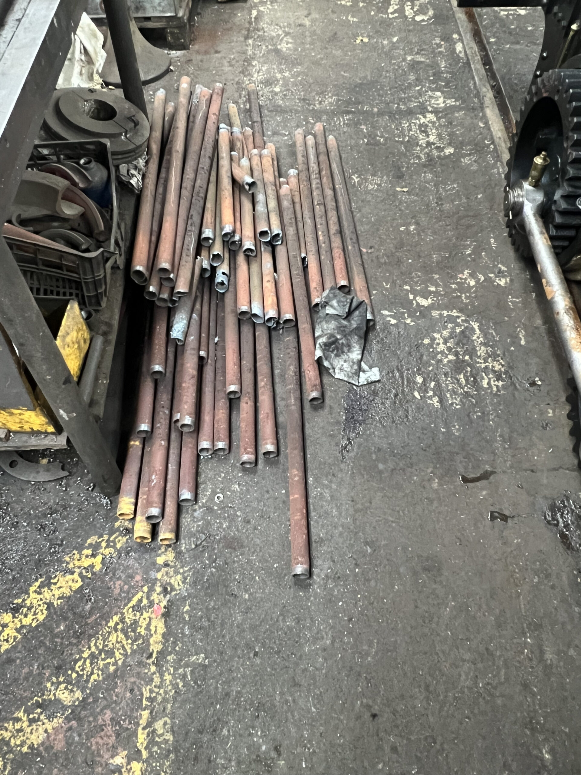
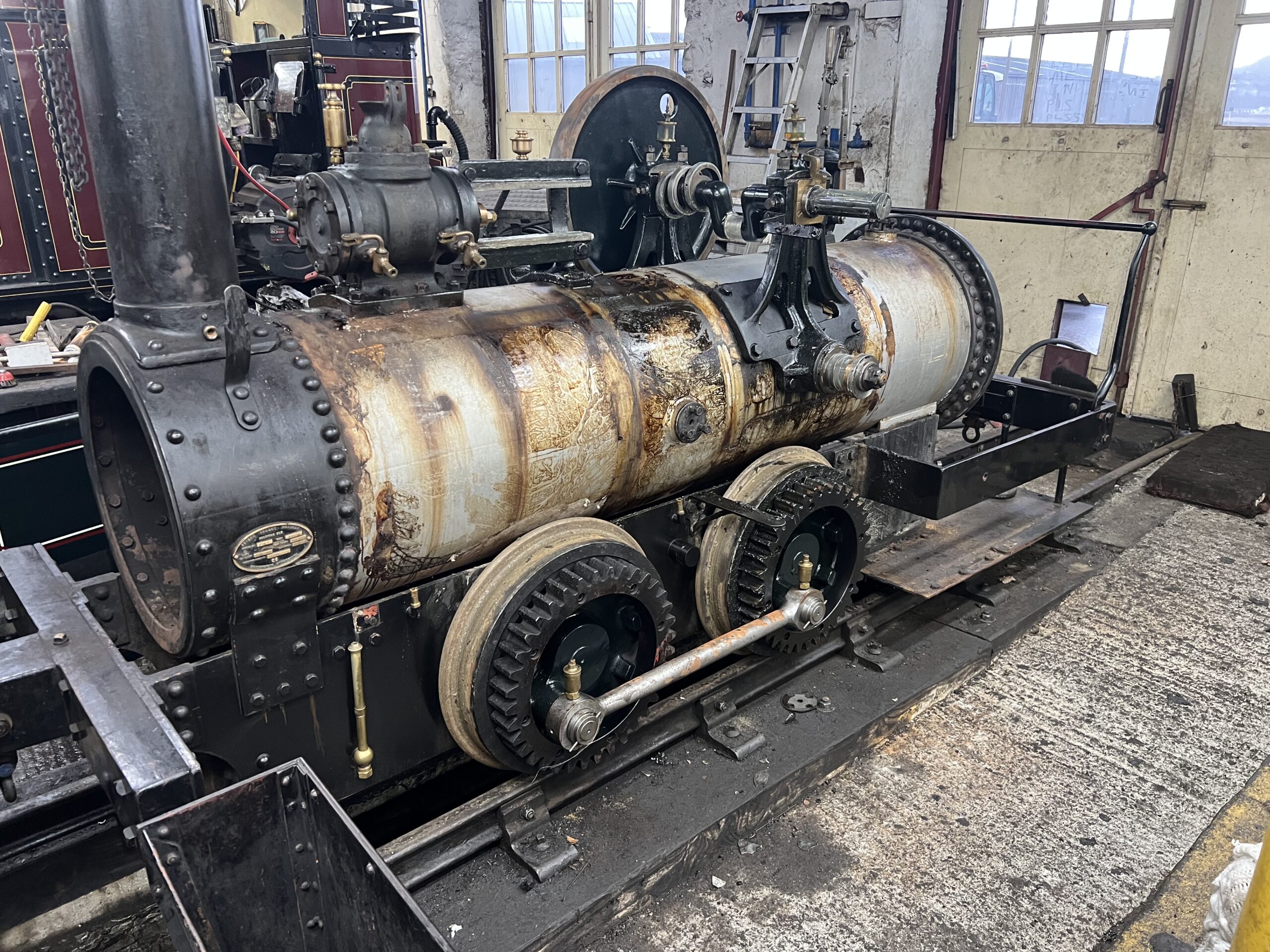
Below: The new tubes – these will be fitted over the Christmas holiday period. The oil staining of the barrel is particularly evident in this photograph – also showing the gap where the crankshaft was. The boiler inspector has already visited and carried out his survey, pronouncing the boiler suitable to proceed to the next examination when the new tubes are fitted and the boiler is hydraulically tested. After that a steam test will follow before the engine can be reassembled and prepared for service.

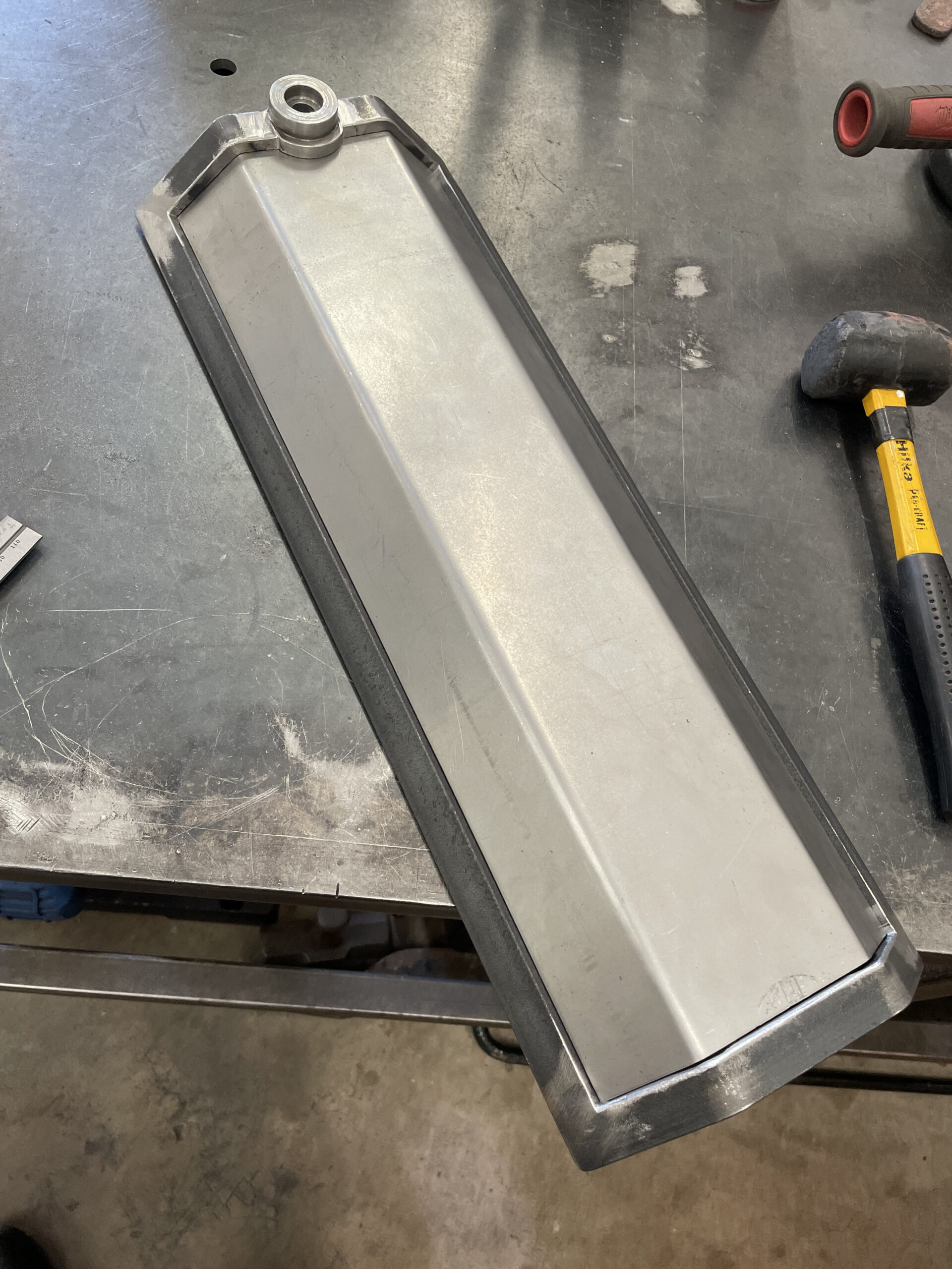
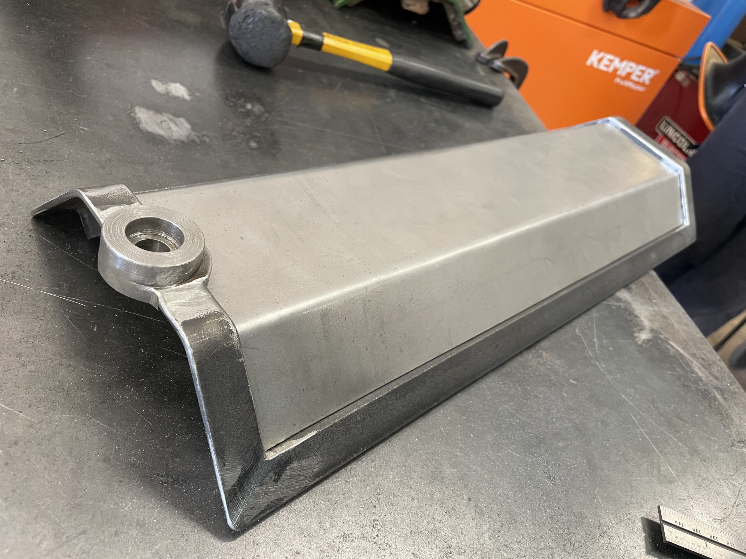
Below: The injector water supply pipe is located quite high up the tank (I think this was originally to allow for any debris settlement in the tank). There is clearance for a pipe below the tank, so for the re-plumbing we will be doing anyway, we’ll fit a take off in the manhole cover on the base of the tank, with an internal filter. The injector can then maximise tank capacity.

Below: The injector pipework has been removed and the section of footplate between the frame cut out and dressed ready for modification as discussed with Paul back at Beamish.
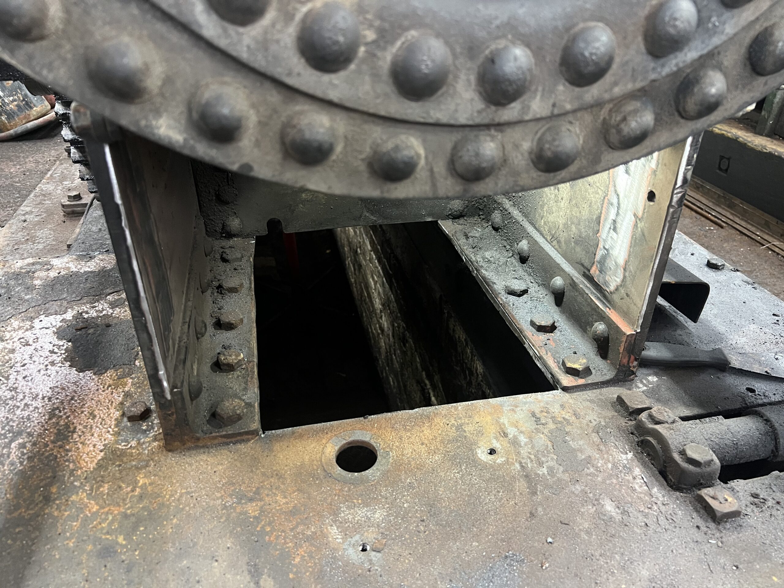
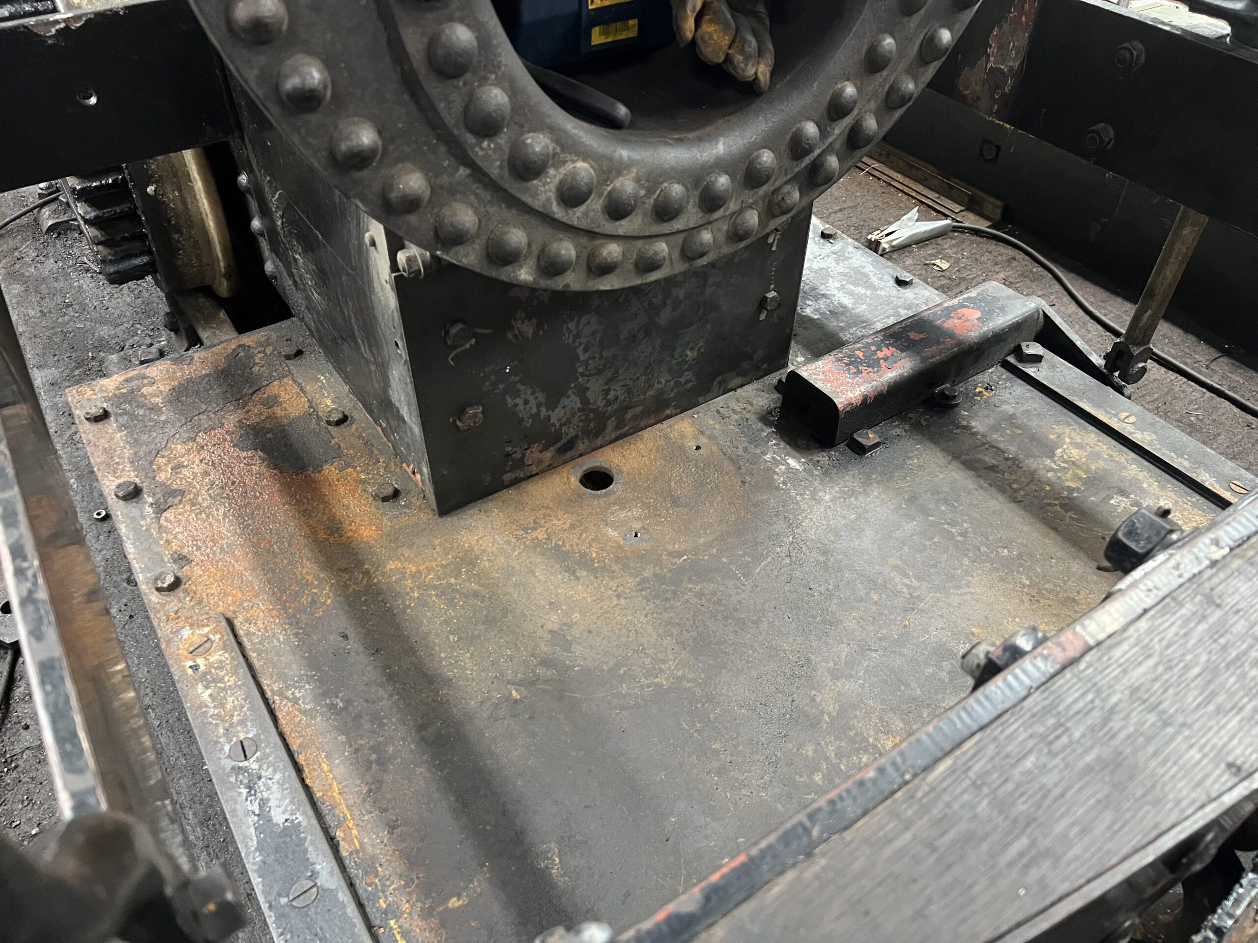
Below: The rear of frames and void for the injector has been plated to keep ash on the footplate or into a box (it previously accumulated in this space). The plate is bolted to two angles which are welded to the inside of the frames, this gives access for maintenance. The plate will get cut outs/hole for, the gauge frame drains, which can then be shortened. There will be a cut out for the live steam to the injector to pass through. The injector overflow I hope to route to the hole in the footplate, for ease of seeing it when operating. There will be a hole for a rod which a spanner can be fitted to, enabling blow down valve operation. Finally, a rod to operate the injector water valve. Everything behind the plate can be accessed from a pit too. which will be available for Samson back at Beamish. [Note from Paul – the addition of the plate usefully brings the appearance of the backhead in line with one of the early engravings of Samson, which was a little ambiguous in it’s depiction of this area but strongly suggested it wasn’t an open space].
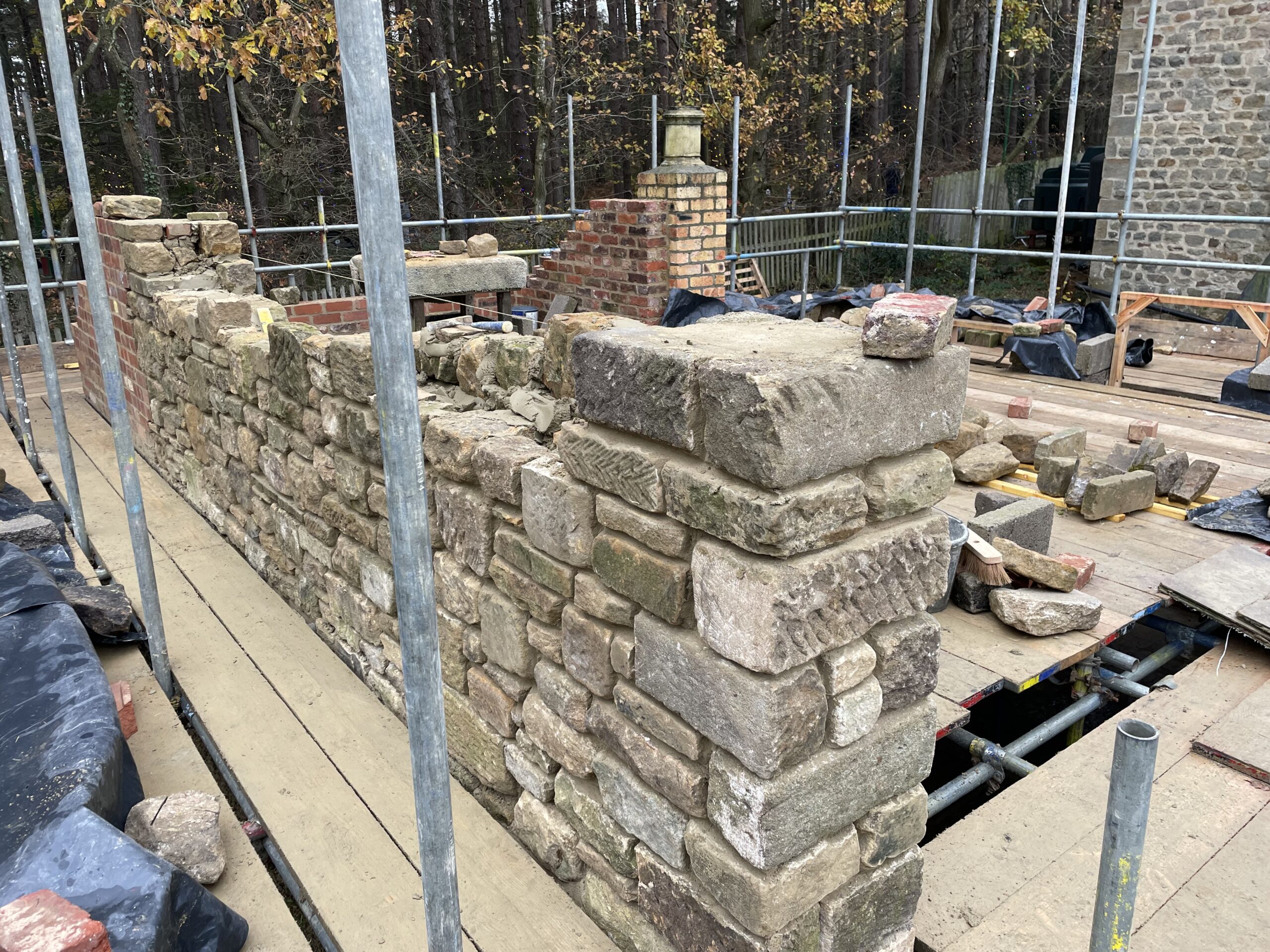
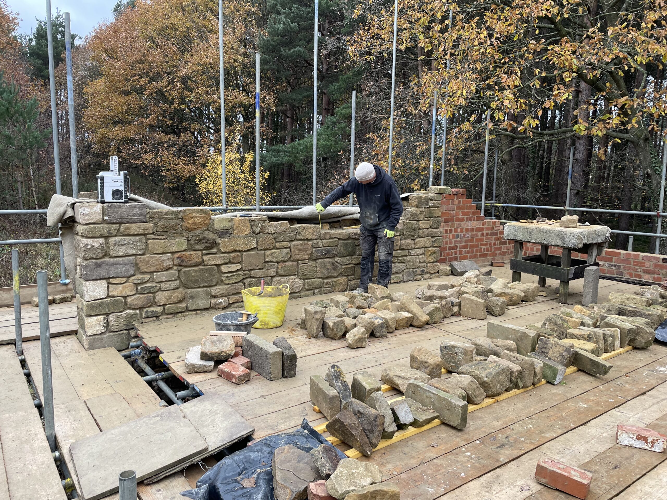
Below: Meanwhile back at Beamish, stone for Samson’s engine shed build is being prepared and some stone-laying has been possible when the weather conditions have allowed. Once all of the walls have been raised to the door lintel height, another scaffold lift will be needed to allow the gables to be constructed.
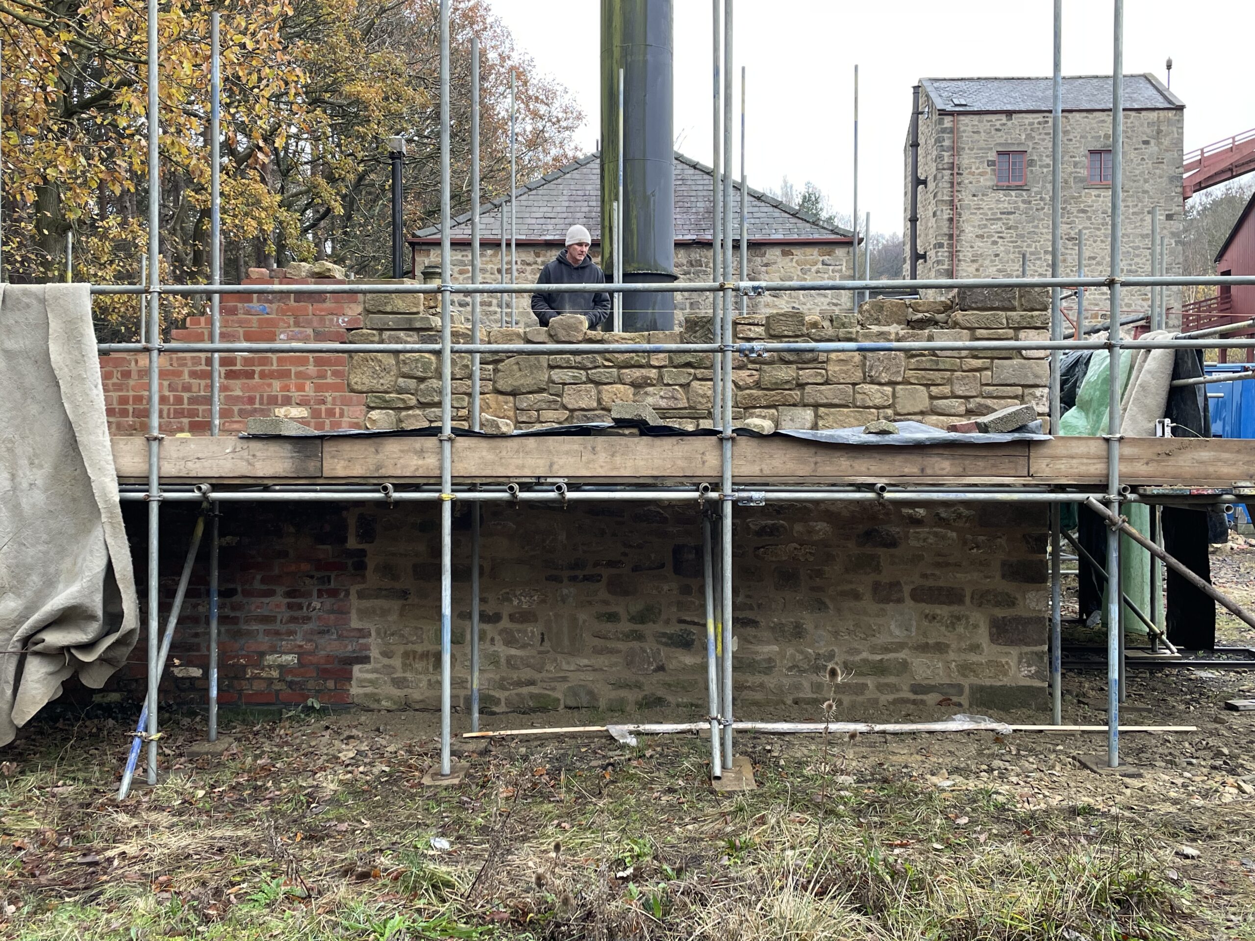
Below: The Front wall top has reached door lintel height, at nine feet above the ground. Pointing and infilling will continue on all sides of the building – the brick wall to the rear is now more or less at it’s fullest height. The chimney pot will be removed too, and the chimney extended above the ridge of the building in due course.
Dunrobin
Below: Some photos taken just before Christmas of Dunrobin showing the boiler in position in the frames, as work on a number of fronts continues to ready it for steam test. The view also shows one of the new brake blocks in place. The engineering team has spent some time on overhauling and assembling the valve/piston rod glands as these are not the more familiar (to us at Beamish) follower and stuffing box arrangement, but are assembled from multiple components that allow adjustment against each other to remain steam tight.
Below: All of the water gauge fittings are being replaced, and as seen in a previous post, these are being adapted for the very specific fit required on Dunrobin’s backhad – flanges having to accomodate longitudinal stay nuts (lower) and the radius of the backhead (upper).
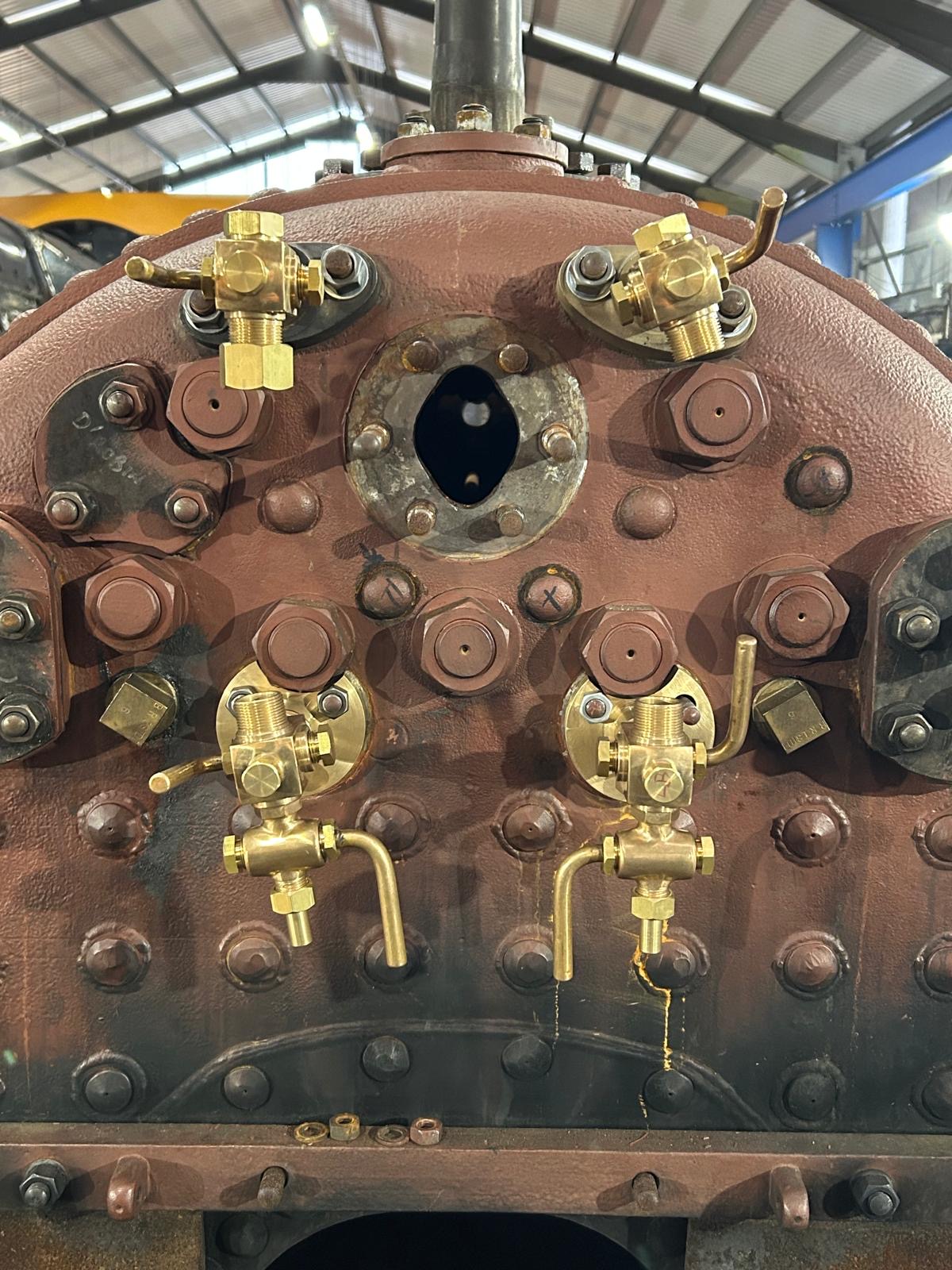
Below: The dome cover has been removed to expose the J pipe (and allow its removal) – this being the component upon which the regulator acts to control the flow of steam from the boiler (at its driest point within the dome) to the cylinders (via the main steam pipe, sometimes known as ‘dry pipe’ within the boiler vessel itself). There was some evidence of leaking in the new J pipe casting during hydraulic testing, so a repair or replacement option is being explored to rectify this.

Tramcars
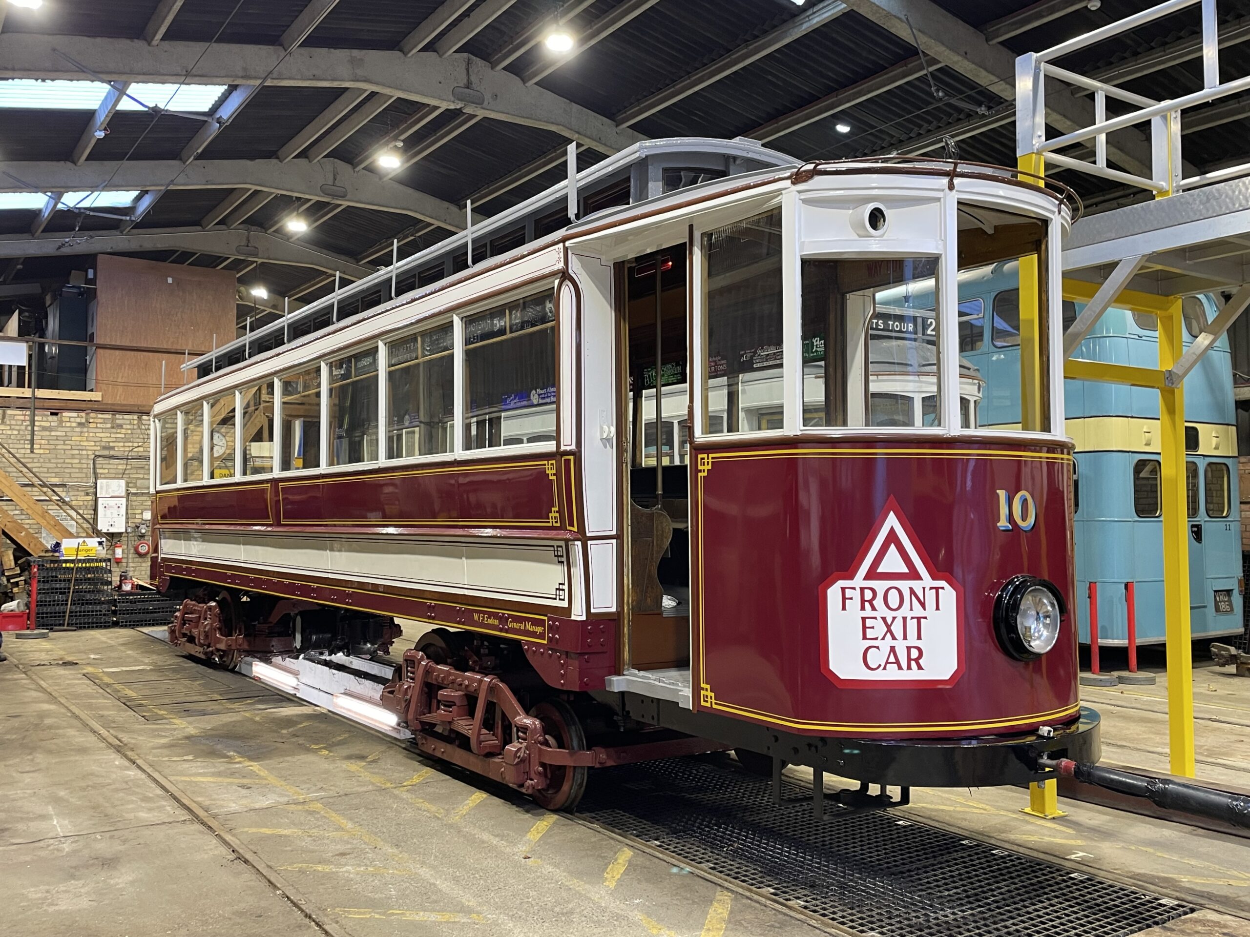
Below: In the first week of the month, Gateshead 10 was shunted from Road 2 onto Road 3 in order to access the inspection pit. This was a first chance to see it in daylight, and also see the side that has been against the wall for the last ten years. Ian and Mick will now continue to reassemble the brakegear components and various overhauled fittings to the underside of the tram.
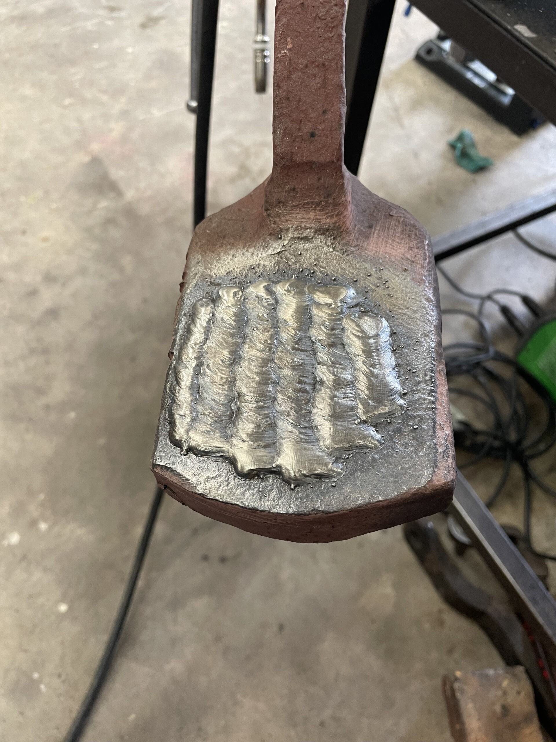
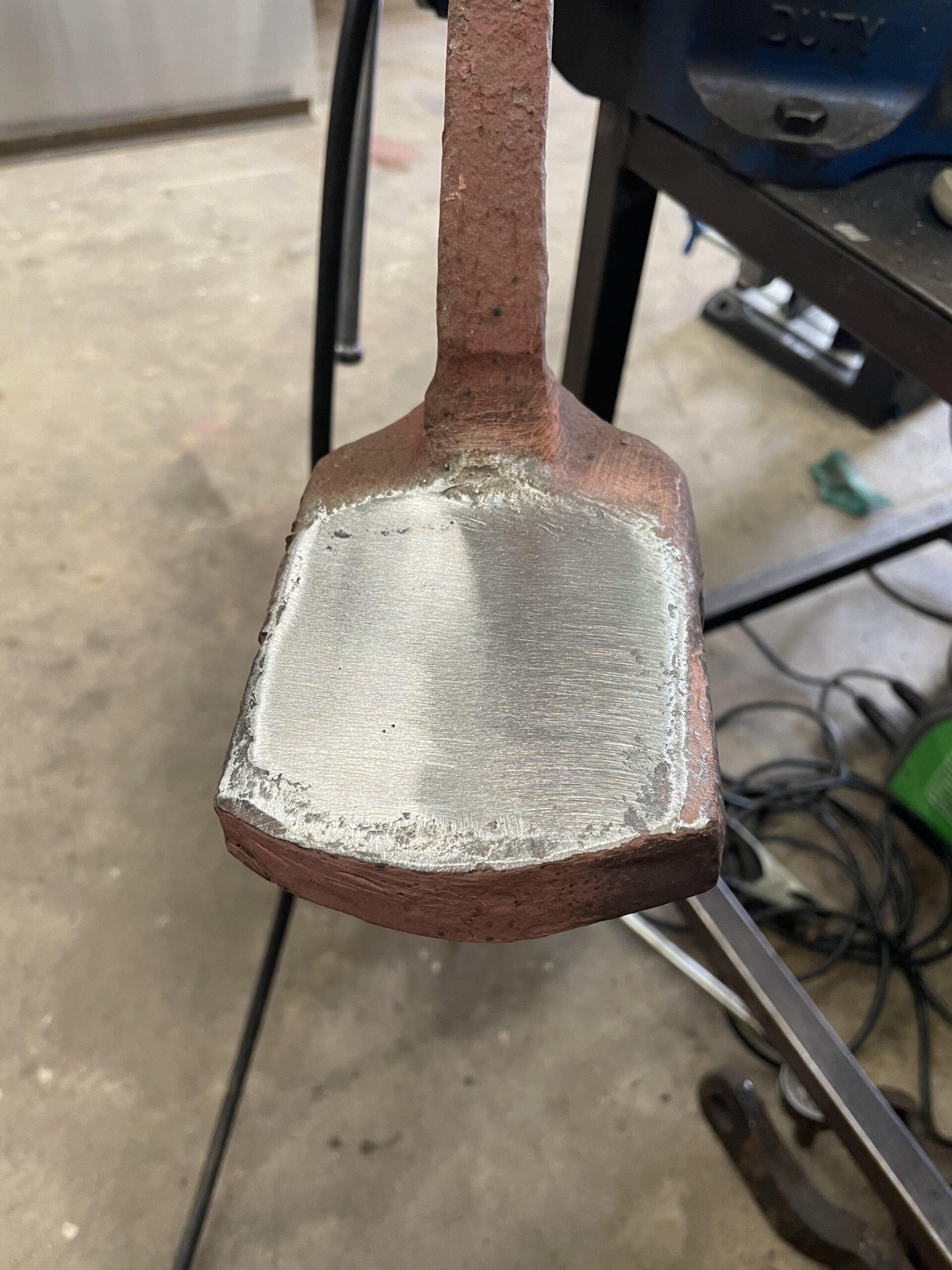
Below: The brake valves for Gateshead 10 have received a great deal of attention over the course of the restoration programme. The two valves are seen here, with one of the removable handles. Of note is the built up (by welding) face on the nearest (lower left), which will be machined true next. This replaces a previous repair on this component, that had not correctly adhered to both contact surfaces of parent metal.

Below: Reflecting on some of the work already carried out on Gateshead 10, here are a few new images of the work carried out on the torque-reaction bars for the motors. They give a good illustration of the process I’ve often referred to as ‘welding up’ on components for this project – so a specific illustration of the process is probably timely. Firstly, we see one of the bars in the raw – clearly the hole has long-ceased to be circular and there is evidence of previous repairs as well as extensive interaction marks with adjacent components.
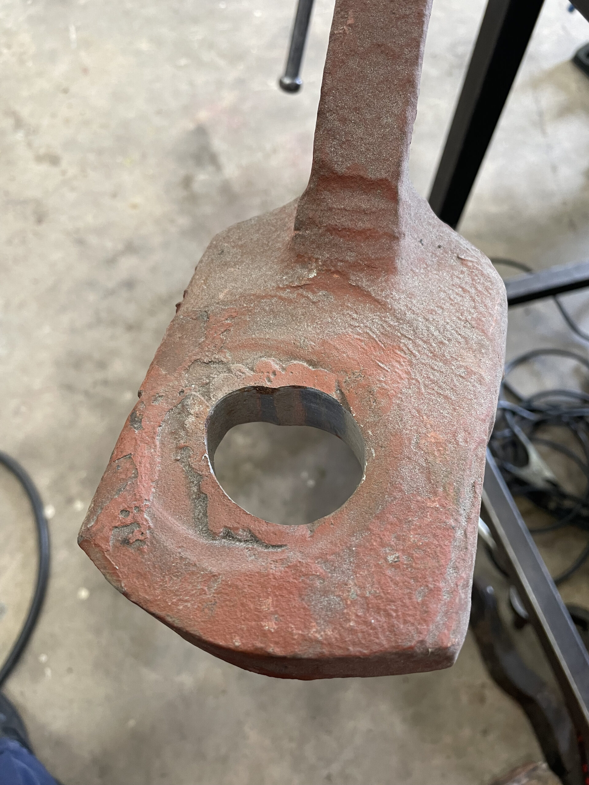
Below: The component is first cleaned up, to reveal what is past repair and what is the parent material (the original bit).

Below: The welds are then applied systematically to remove the hole and also surface degradation.
Below: Finally, the weld is dressed off and checked for integrity. The component is then ready for drilling of new (and circular!) holes, and then painting. Chris noted that it would be interesting to track the mileage of MIG wire employed on Gateshead 10 over the years – and this is a good example of just one hole, in dozens as practically every bolt hole on the bogies has had to be simiarly treated.
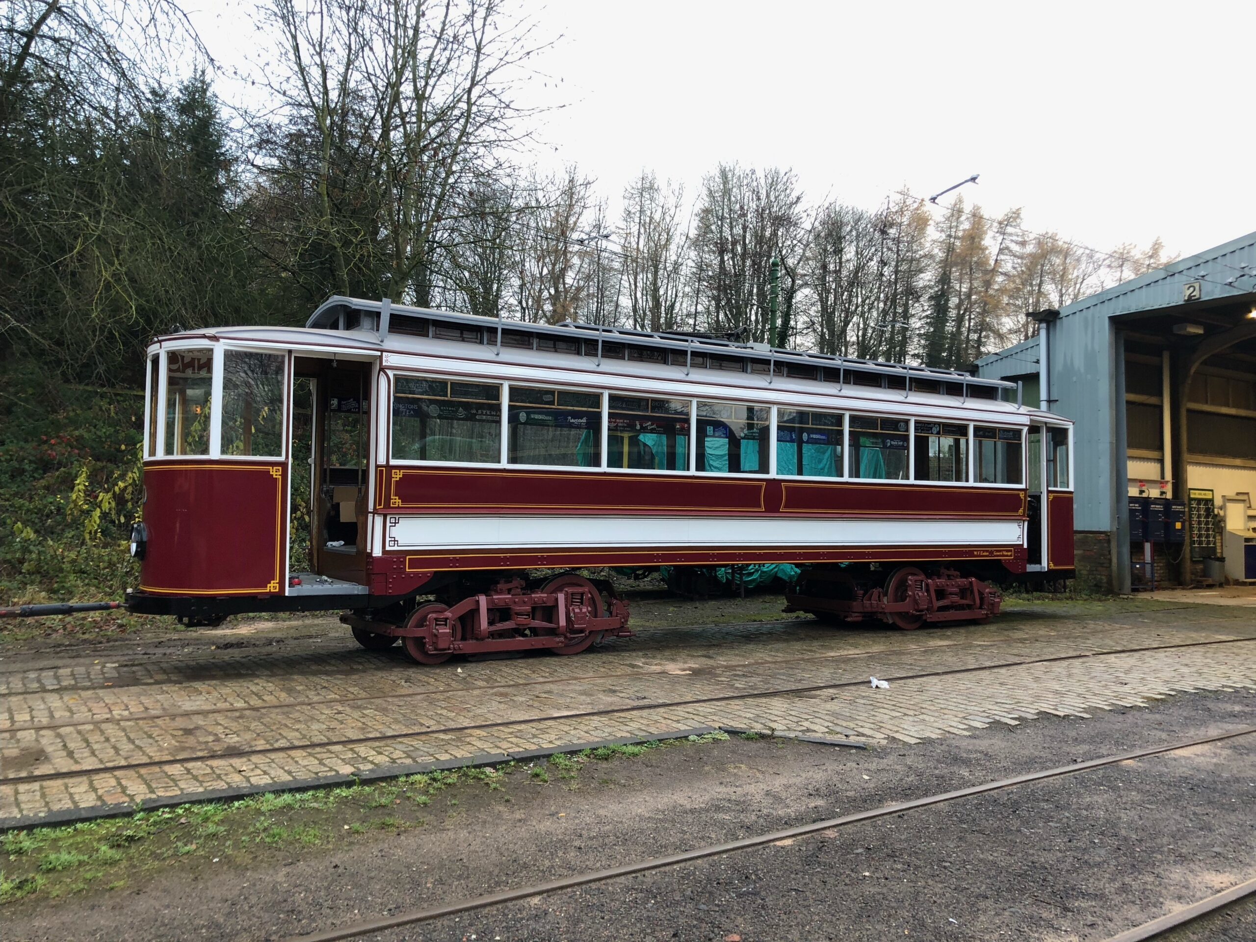
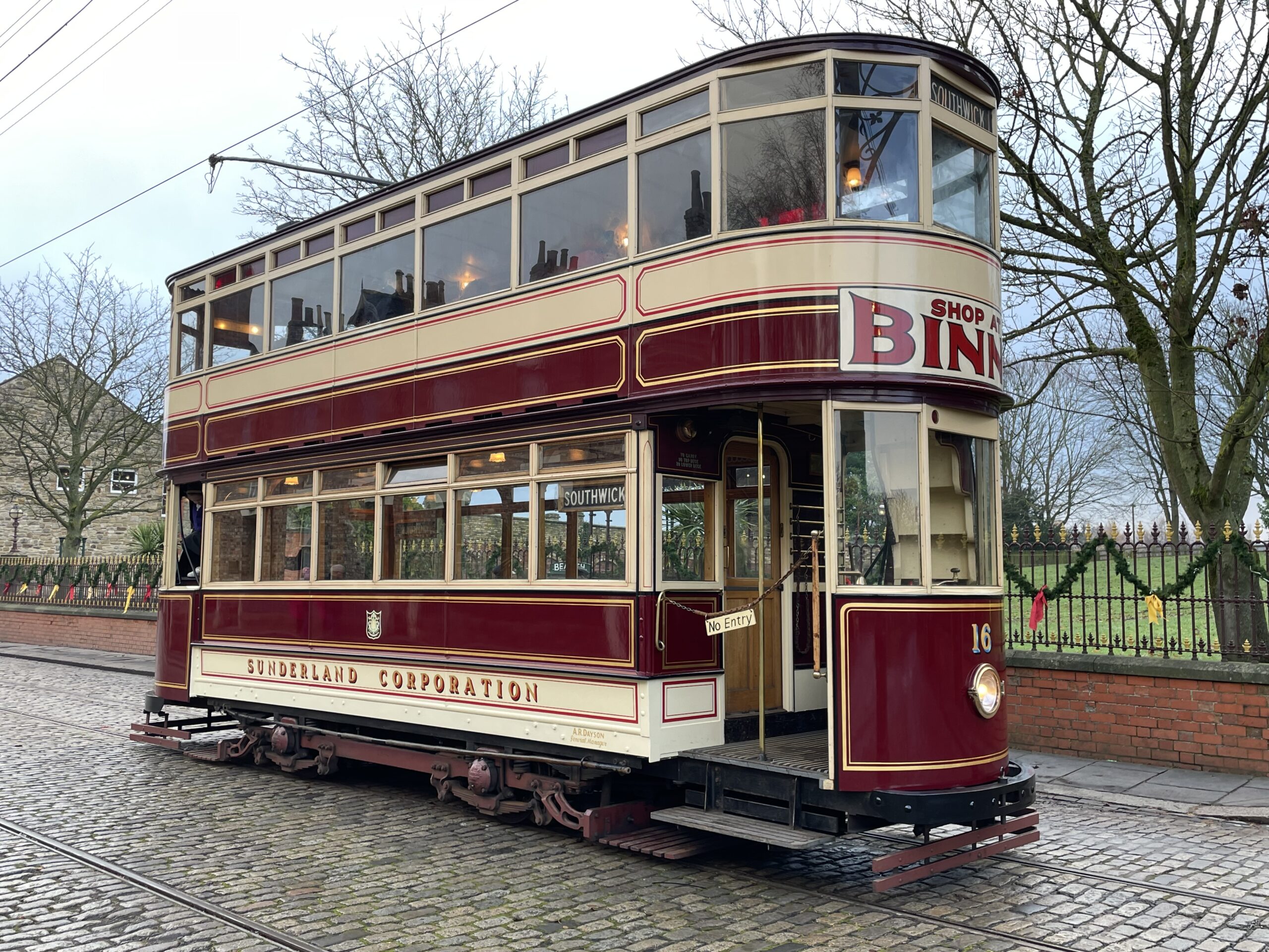
Below: Sunderland 16 – an image taken outside in natural light, to show the new lettering on the rocker panels.
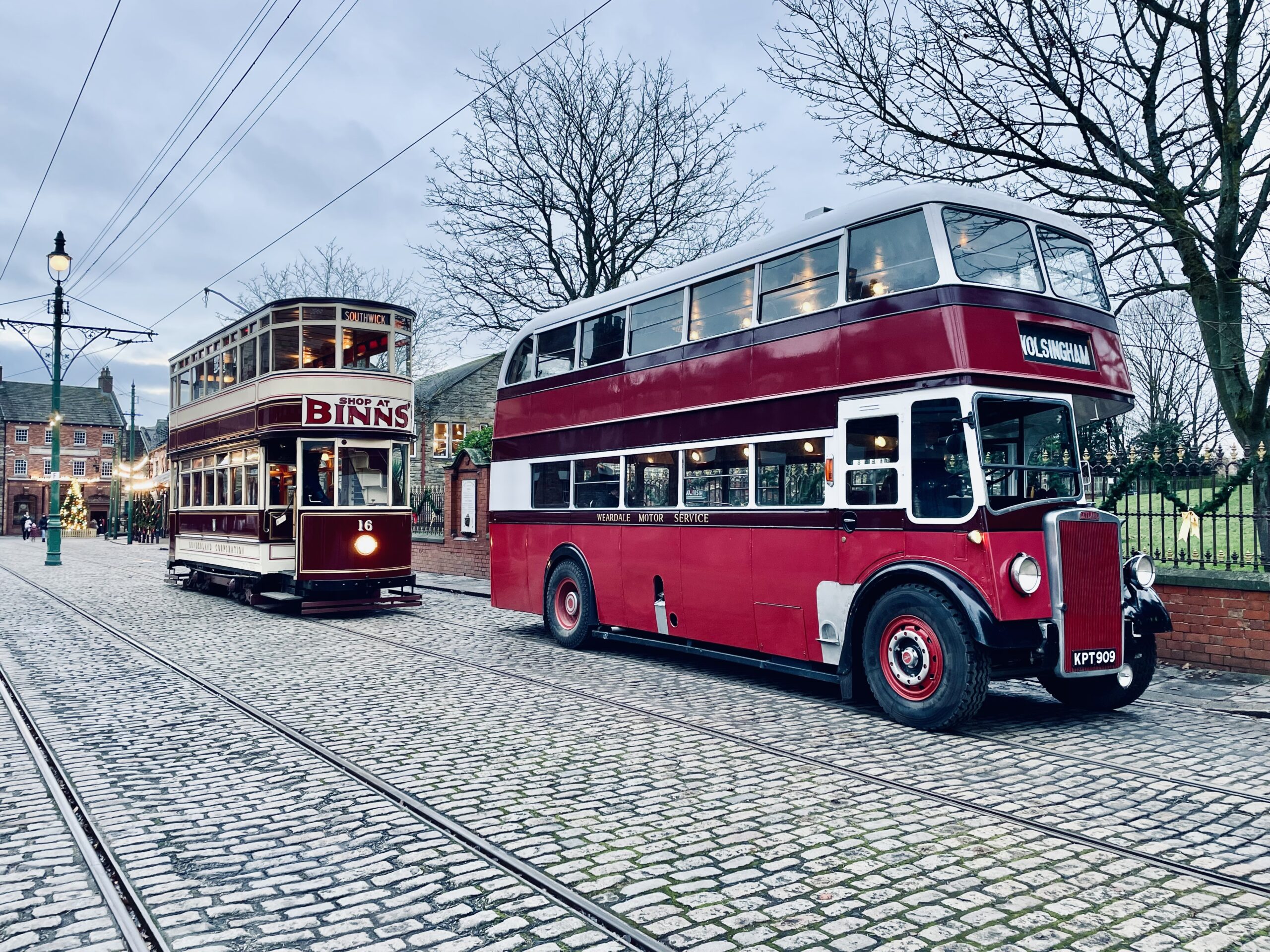
Below: The familiar winter operation sight – Sheffield 264, Sunderland 16 and the B-Type bus. Blackpool 31 and Oporto 196 have also been out (the latter being a popular driver-training tramcar). KPT 909, the Scouts Leyland and Crossville 716 have provided an all-Leyland bus service on weekdays too – the engine in the B-Type replica is a Leyland 401 diesel engine, so after a fashion this counts too!

Buses
Below: Work on West Hartlepool 36 has continued, with the repaired exterior panels painted and the saloon electrical system receiving attention. The seats have been removed and sent to Liverpool Coach Trimmers for re-upholstering.
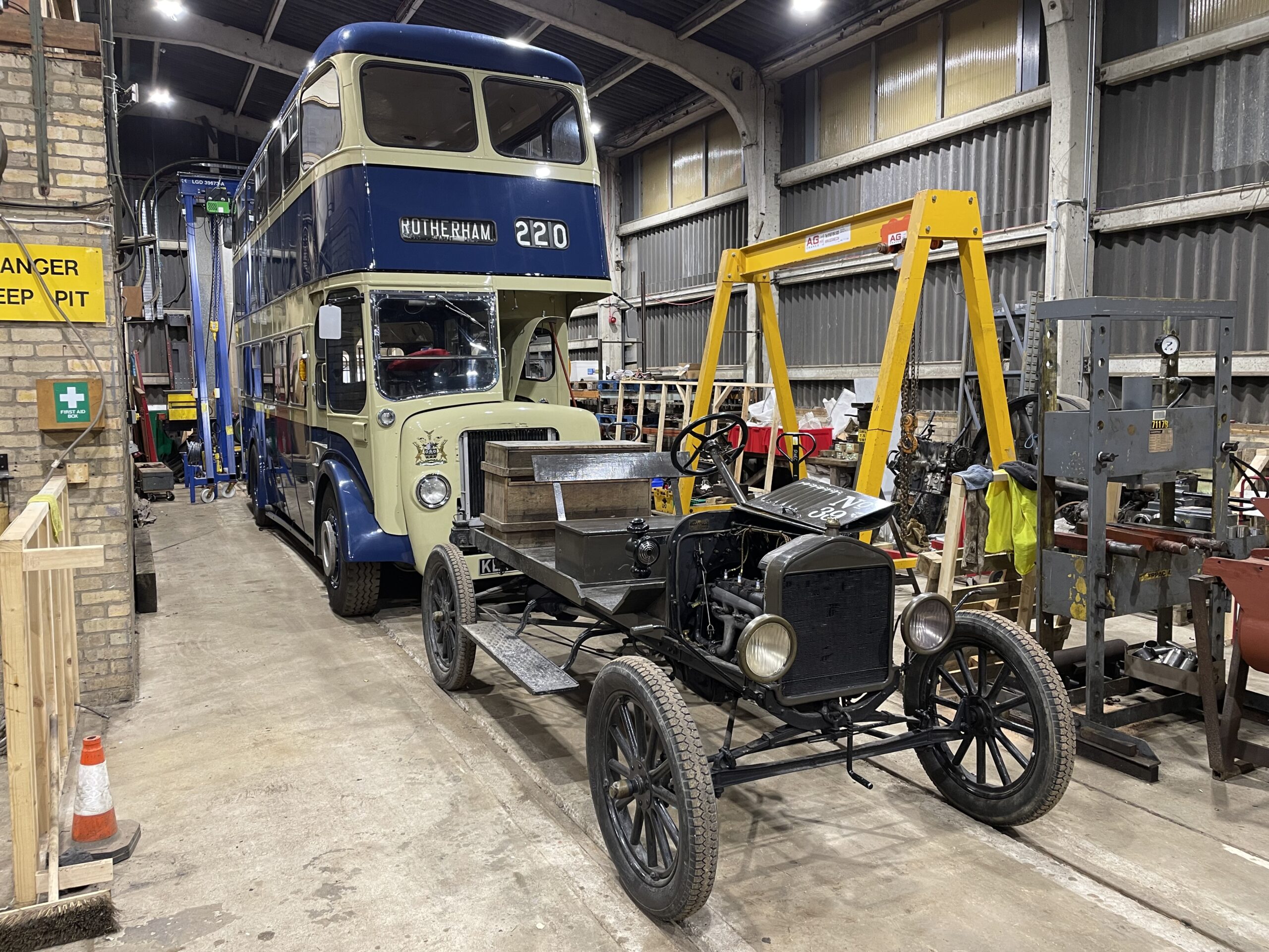
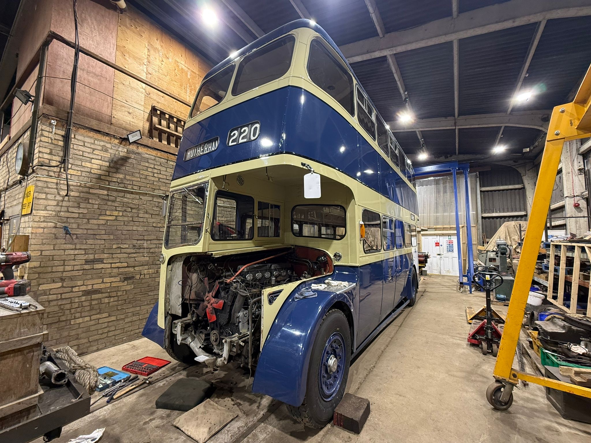
Below: Rotherham 220, with newly upholstered seats back on site, has moved to the rear of the tram depot to be prepared for its engine transplant.
Below: By the week ending the 12th December, the radiator had been removed and various other disconnections made as a start of the process.
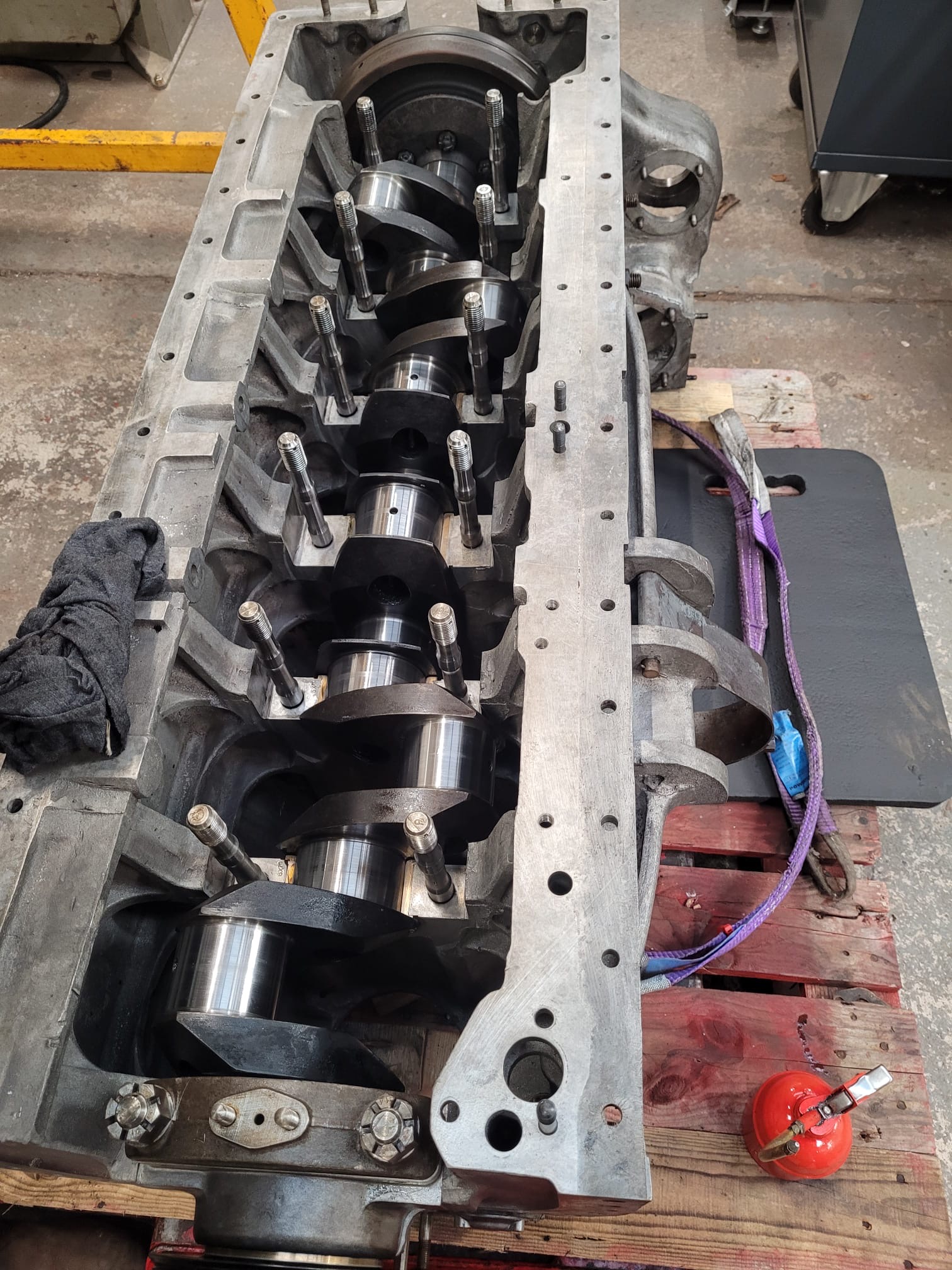
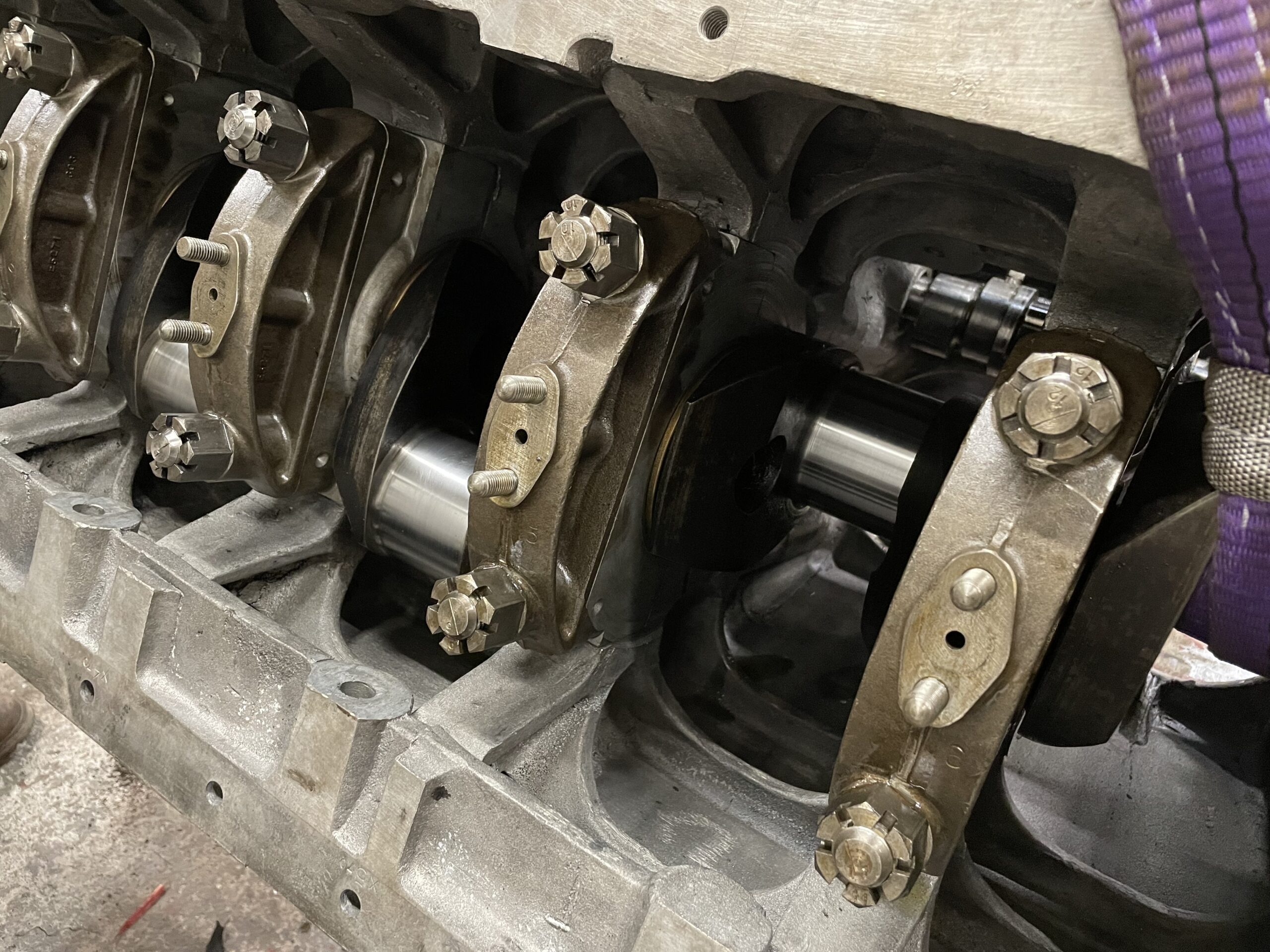
Below: The overhauled engine block has arrived from the contractor and Phil and Phil have already started to reassemble the engine for 220. Here the crankshaft is seen in place.
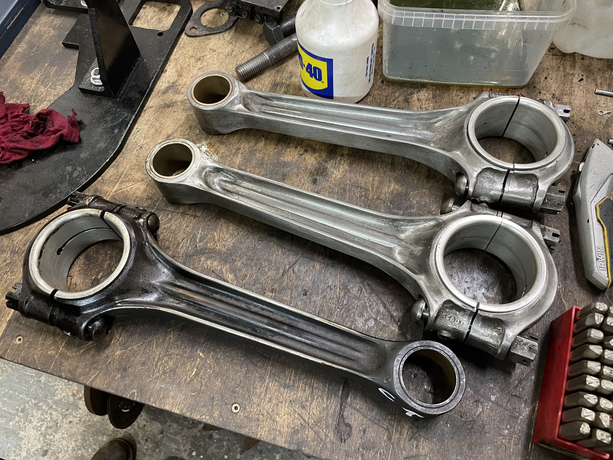
Below: Some of the connecting rods for the engine – note the very high quality of finish on these components which were being marked up with their positions within the engine at the time of this photograph.
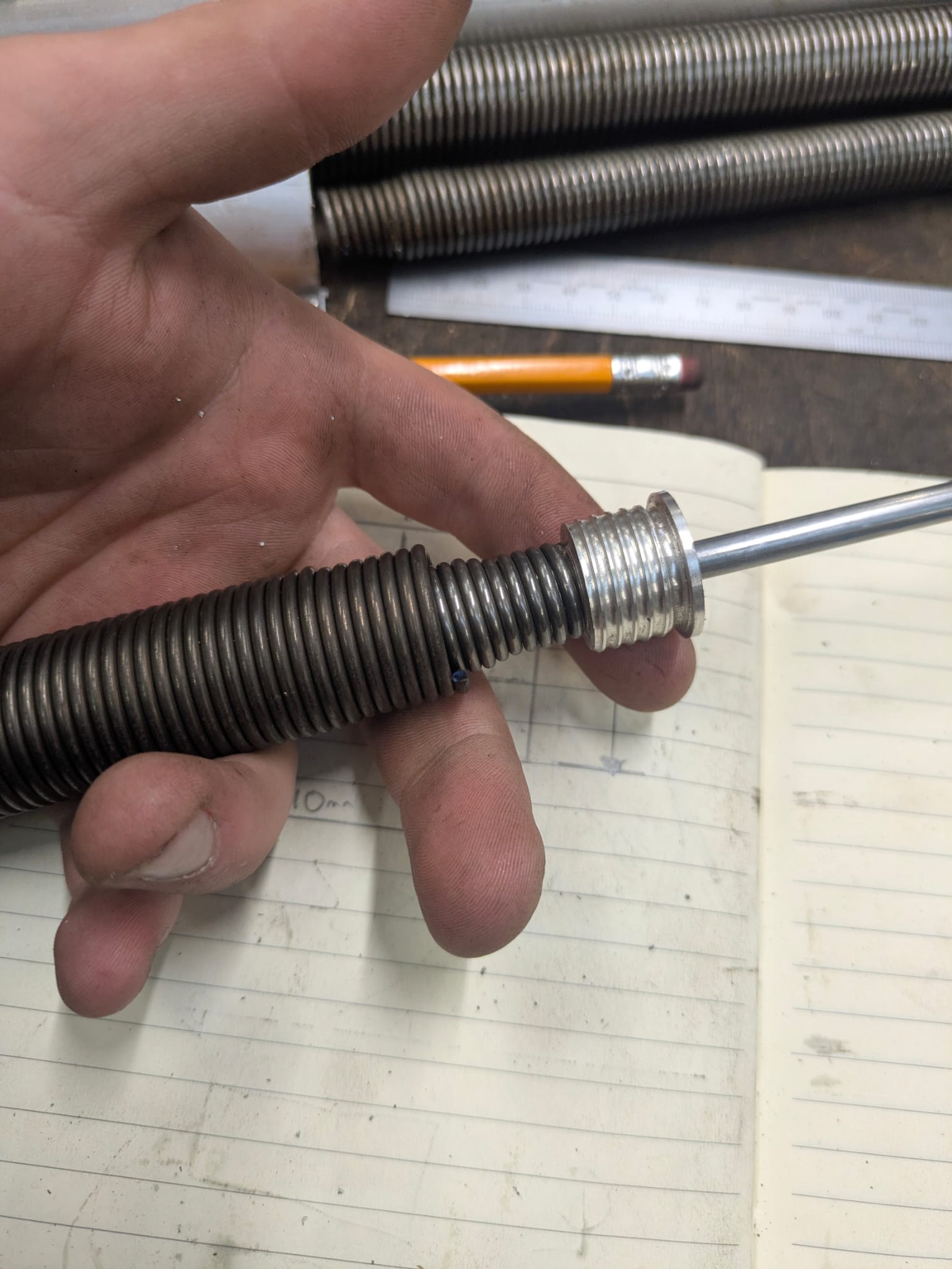
Below: Work on Sunderland 2 has been limited due to the restricted access whilst the bus is parked in the depot, but some jobs have progressed, including the replica window-drop mechanisms. Sam, our apprentice, has manufactured new units to replace those missing and by reverse-engineering those that were complete. The springs for these alone have cost the best part of £800 but the result is an accurate and operable drop window, and to not have them all working would have been a great shame.
The mechanism consists of two springs, one inside the other, contained within a cylinder and with a shaft through the centre. This is all held captive using end-caps, one of which is seen here after Sam had manufactured a set of them. The principle is identical to the up-and-over garage door mechanisms that many readers will be familiar with.
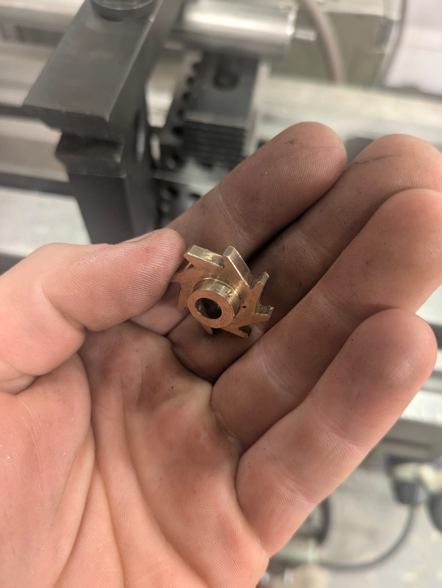
Below: This ratchet sits on the end of the shaft, and is secured to it. It engages with a fitting on the bus and enables the springs to be pre-tensioned.
Below: A completed spring unit ready to fit into the bus.

Below: One of the original mechanisms on the bus – the cylinder can clearly be seen, around which is wrapped a cable at each end to the window itself. The catch in the centre of the view secures the window in whatever position is desired. The torsion of the springs within the cylinder positively hold the window in position, anywhere between fully closed and fully open. The action in use is a very smooth one and one that is pleasingly ‘interactive’ for passengers.

Below: A close-up view of one of the new cylinders complete with the wire that connects the window to the mechanism and can wind on/off the cylinder. The ratchet can be seen here, engaged with a fixed pawl on the mounting bracket.

Armstrong Whitworth Limousine
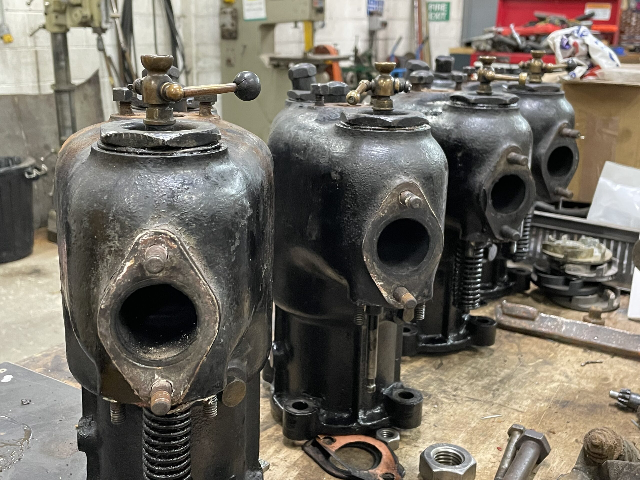
Below: Work is being undertaken on the AW car over the winter, as a mix of volunteer and staff labour. The cylinders have been removed from the crankcase, and have revealed some issues where the connecting rods fit the crankshaft, which will mean that the rest of the engine will be removed from the car and moved to the workshop for attention over the winter months.
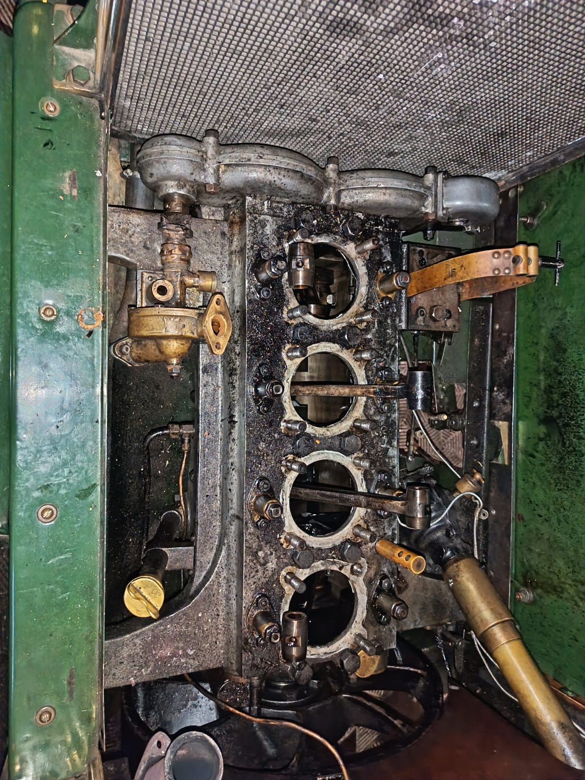
Below: The cylinders – separate castings with no ‘head’, as is conventional on later engines. Evidence of dual ignition has prompted a revision to the winter plan to look at including this within the work being undertaken, and also to look at whether a small pump to pressurise the fuel tank can be replicated/reproduced as well.
Below: New pistons have been designed by Chris so that they can be issued as a tender for manufacture of a new set, plus spares. These will be marginally oversize, partly to reduce the displacement and therefore increase the compression in order to cope better with modern petrol octane levels and additives.

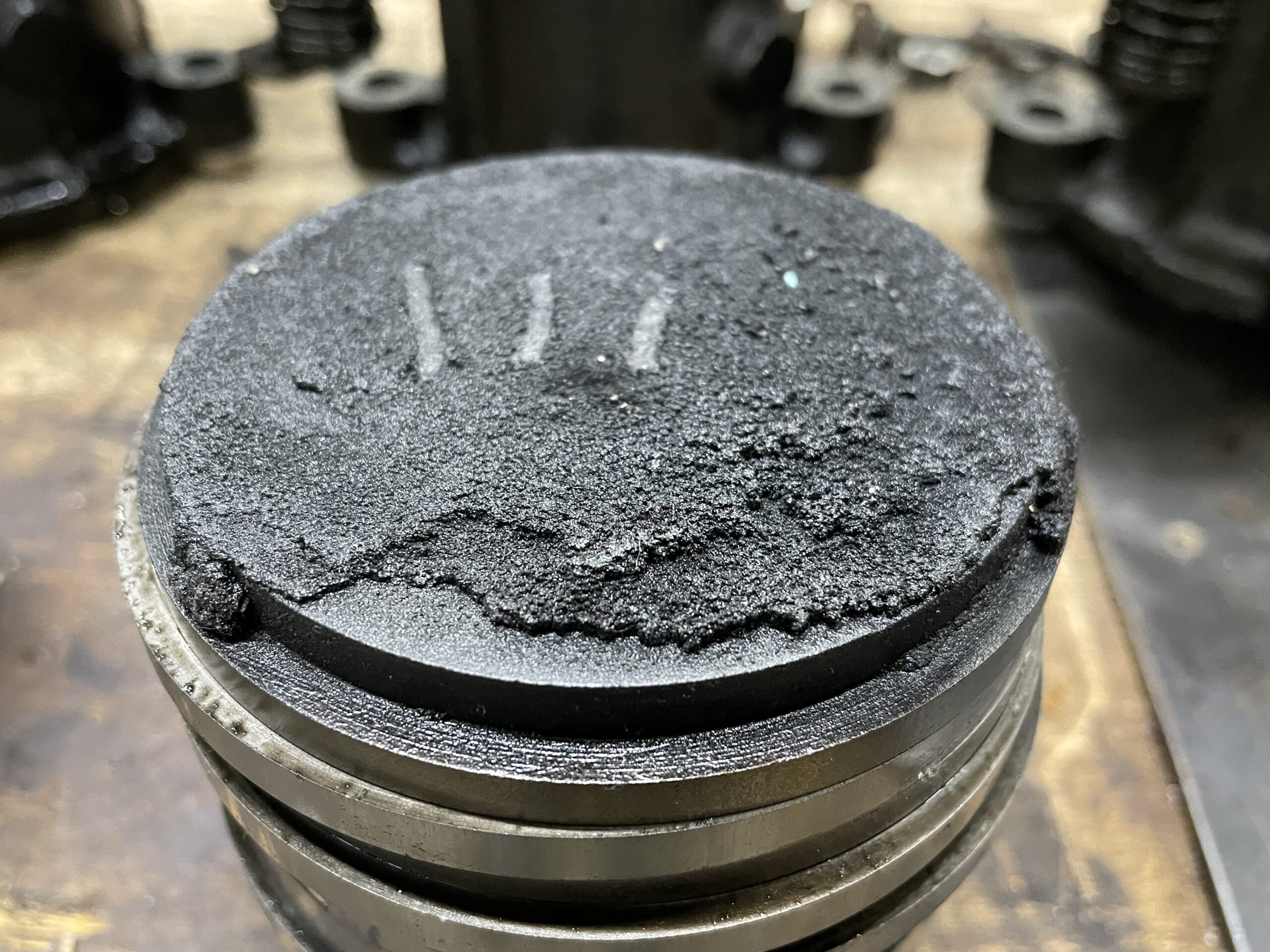
Below: One of the pistons, showing the amount of carbon that had built up on the crown. The new pistons will be machined for fitting the rings at Beamish, in order to take a standard sized ring and include an oil control ring.
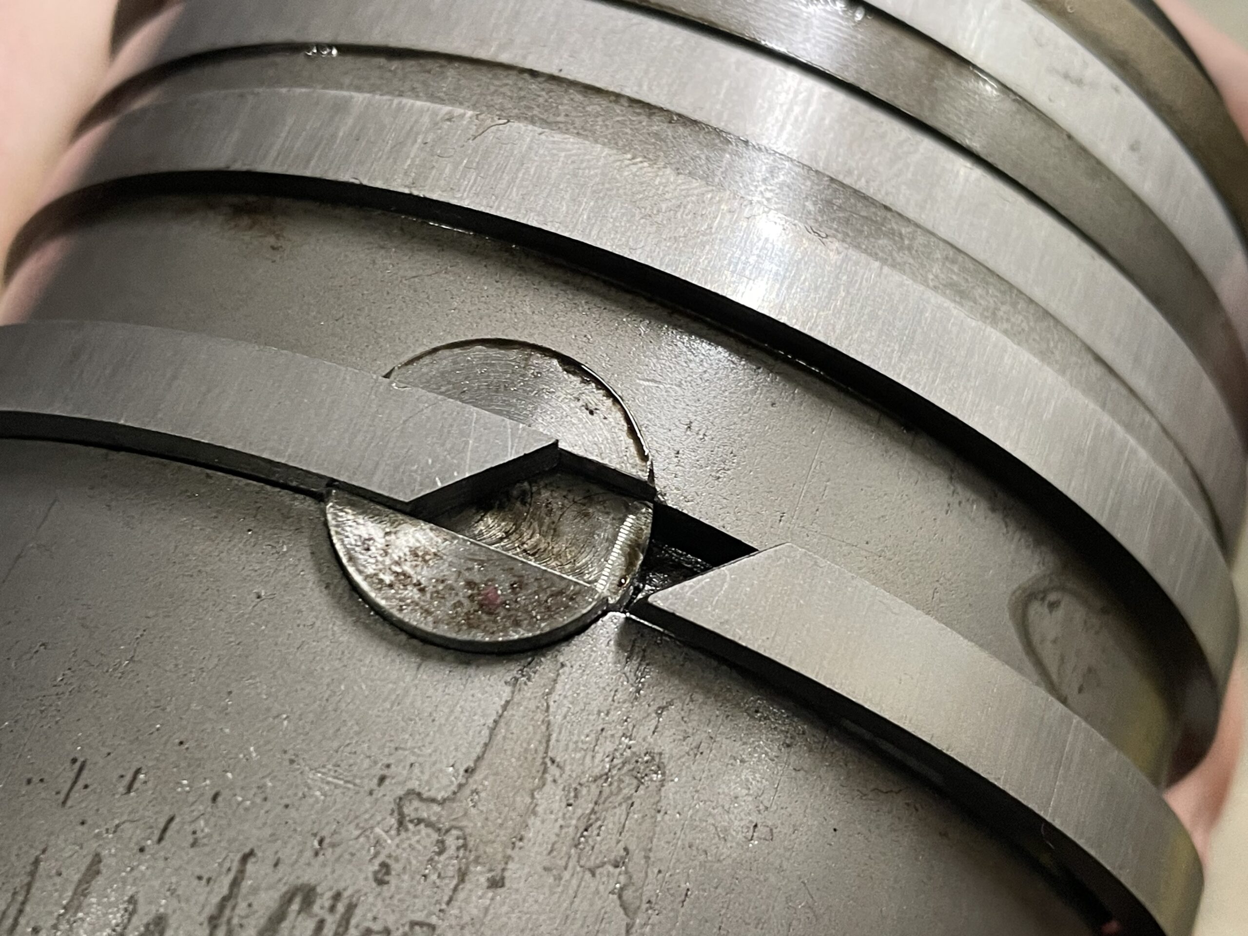
Below: A close-up view of the arrangement by which one of the rings fits into a slot within the head of the gudgeon pin – to prevent this from rotating.
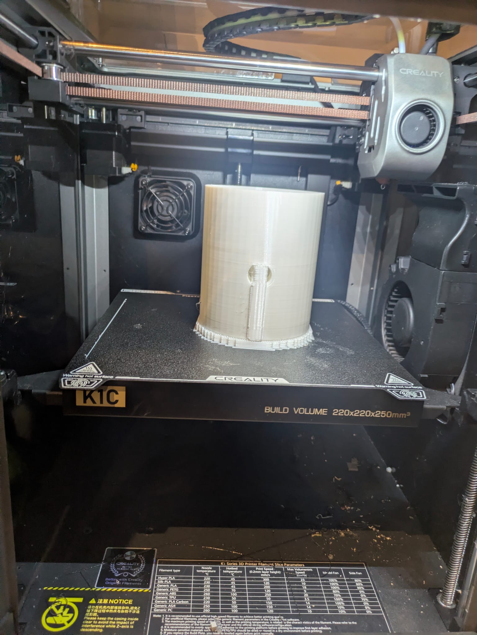
Below: Sam 3D printed a slightly enlarged piston, which was fitted into one of the cylinders to establish what the clearance for it would allow. Here is the design, being worked up ready for printing.
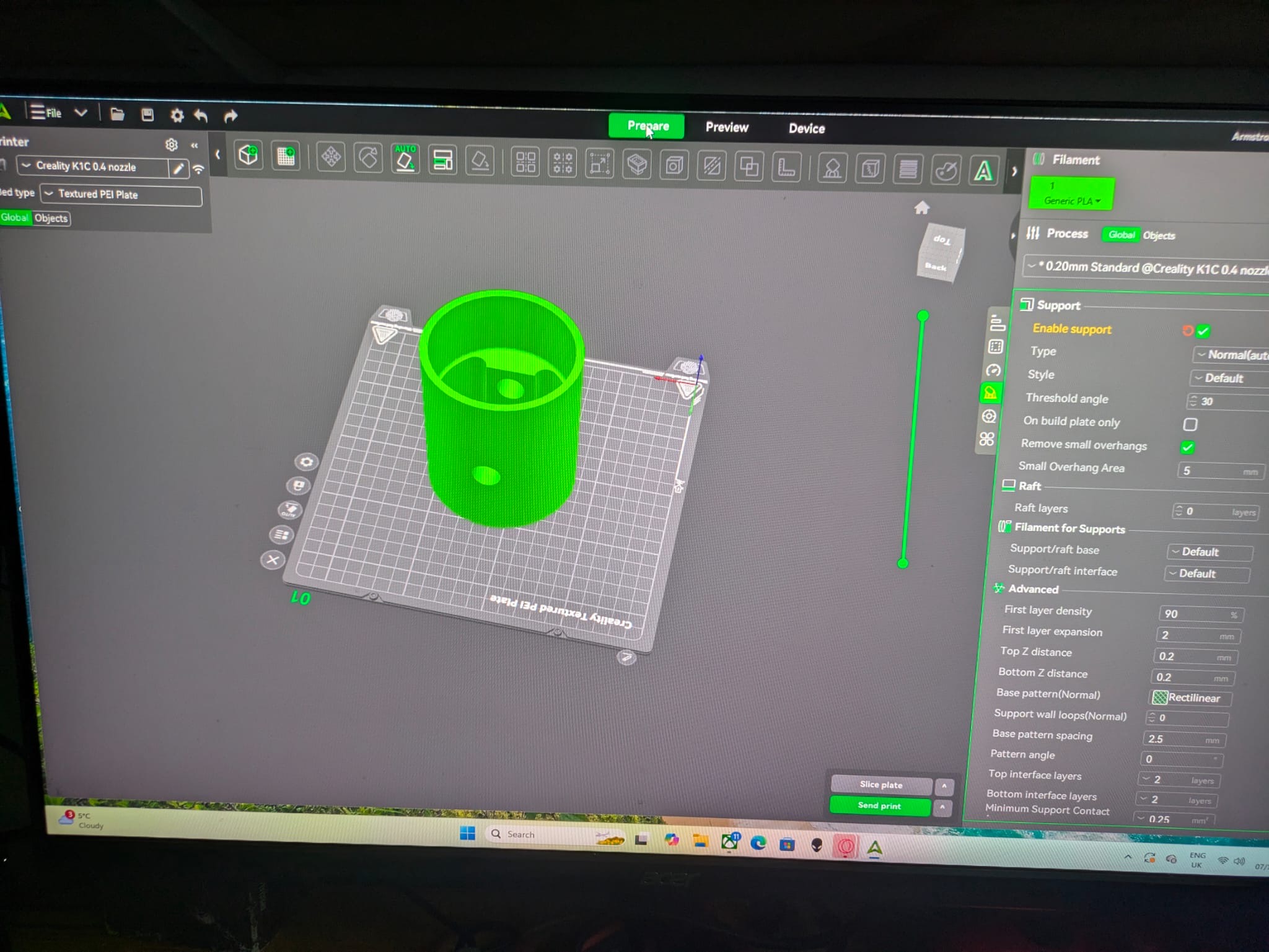
Below: The printer at work – it is clever in what it doesn’t print, as much as it doesnt. When creating castings, various core boxes are required to prevent metal from being where you don’t want it – with printing, the space (in this case the partly hollow interior of the piston) can be created simply by not printing it (see second photo below).
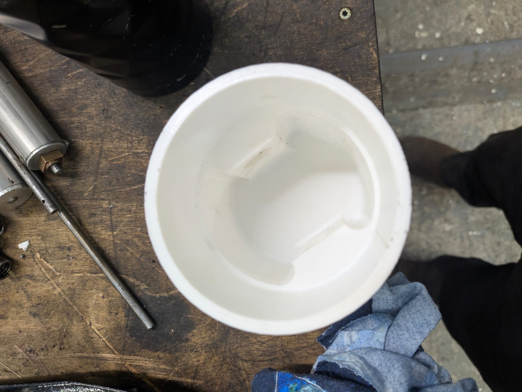
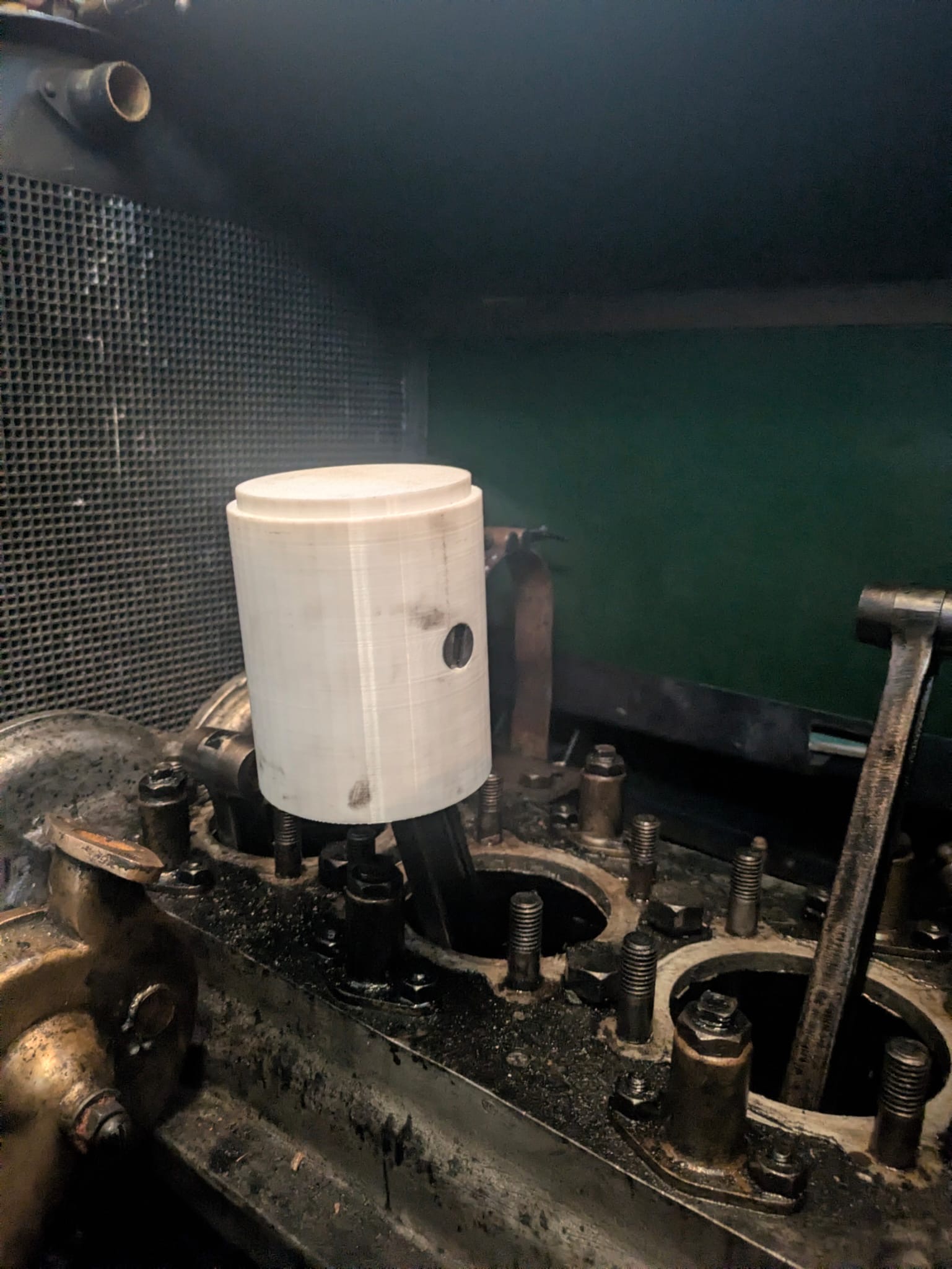
Below: The print is durable enough to allow it to be handled and fitted to other components – in this case it has been located onto one of the connecting rods using an existing gudgeon pin.
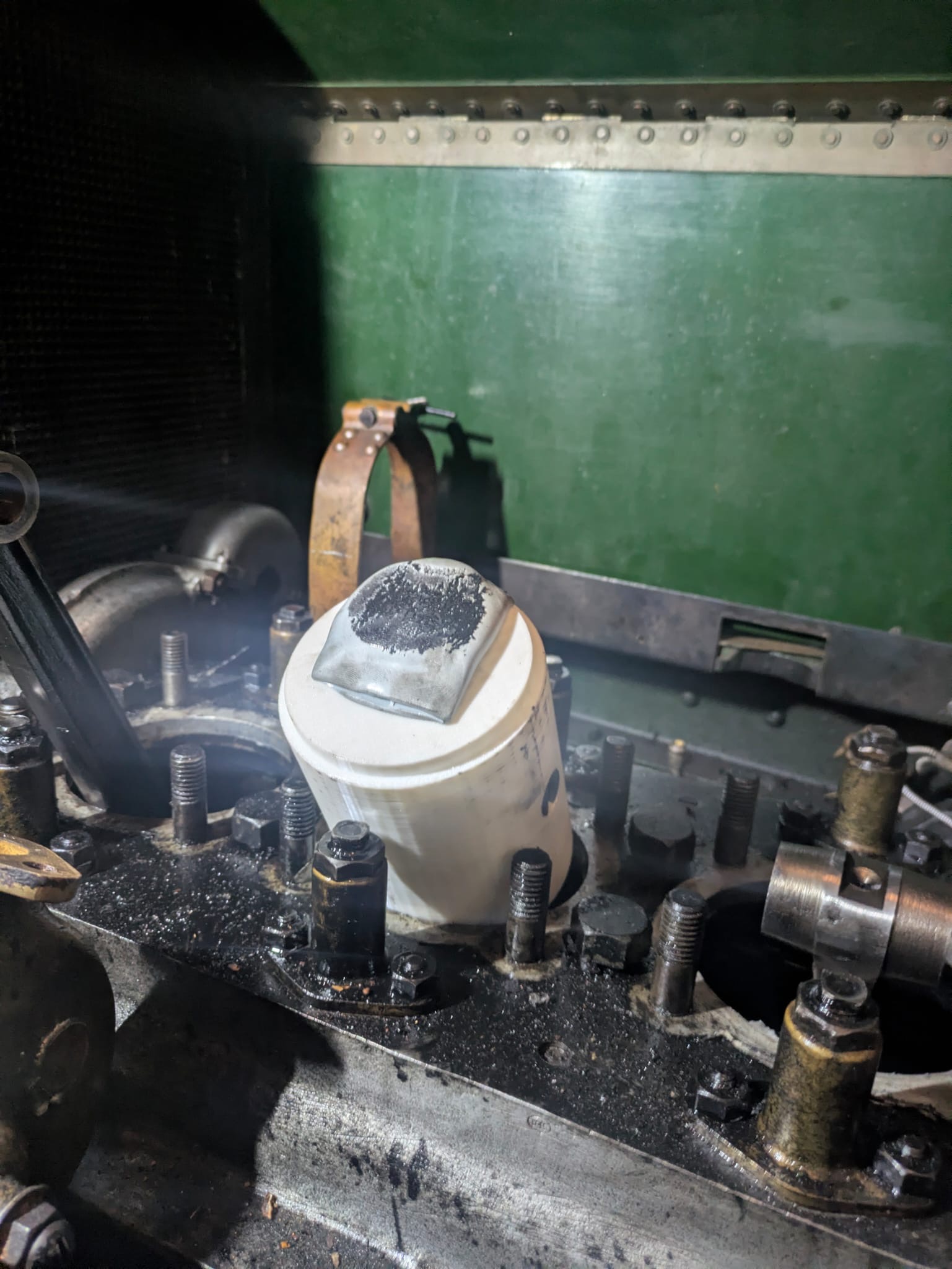
Below: The re-usable putty (avoiding brand names here!) has been placed onto to the top of the piston head, then the cylinder was fitted back onto the crankcase (with the piston inside) and the engine turned over by hand. The resulting witness mark on the putty reveals both the available clearance and also allows calculation of the machining allowance needed. The manufacture of the aluminium pistons has being tendered, as a CNC producer can more economically manufacture the actual pistons, to a fixed price, than we can. Final finishing will take place at Beamish, including the clearances for the piston and oil rings.
Below: A render of the design work that has been used to procure the pistons for the Armstrong. This is a cost-effective way for us to obtain repeatable components, and the price difference for eight of these over four is negligible, so that a set can be put into stock for the car as well.
![]()
Study of contemporary literature about the marque has revealed some other features that are not present on our car, but explain various holes and witness marks. Therefore, research will continue with a view to replicating these missing items and installing them over the course of the next few years. We don’t want to dismantle the car to a point that it becomes unavailable each season, so the work will be confined to each winter, which allows plenty of time in the programme to carry out this work.
Tramway Overhead Line Equipment
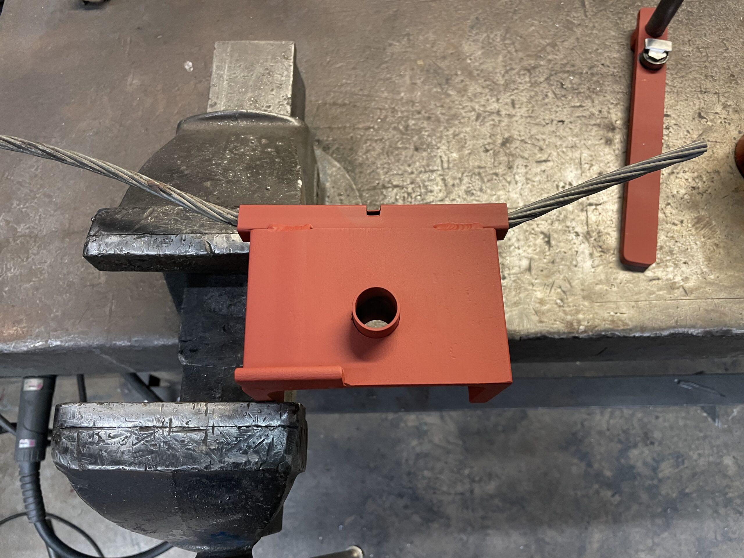
Below: This sequence of photos shows the process of forming the eyes for replacement span wires – part of a programme of renewal that is taking place across the whole Tramway. New spanwire and fittings (largely in stainless steel) are being employed, as are replacement insulators where applicable.
This photo shows the spanwire inserted into a square tube that is attached to the jig. This then allows two pre-bending operations to be carried out.

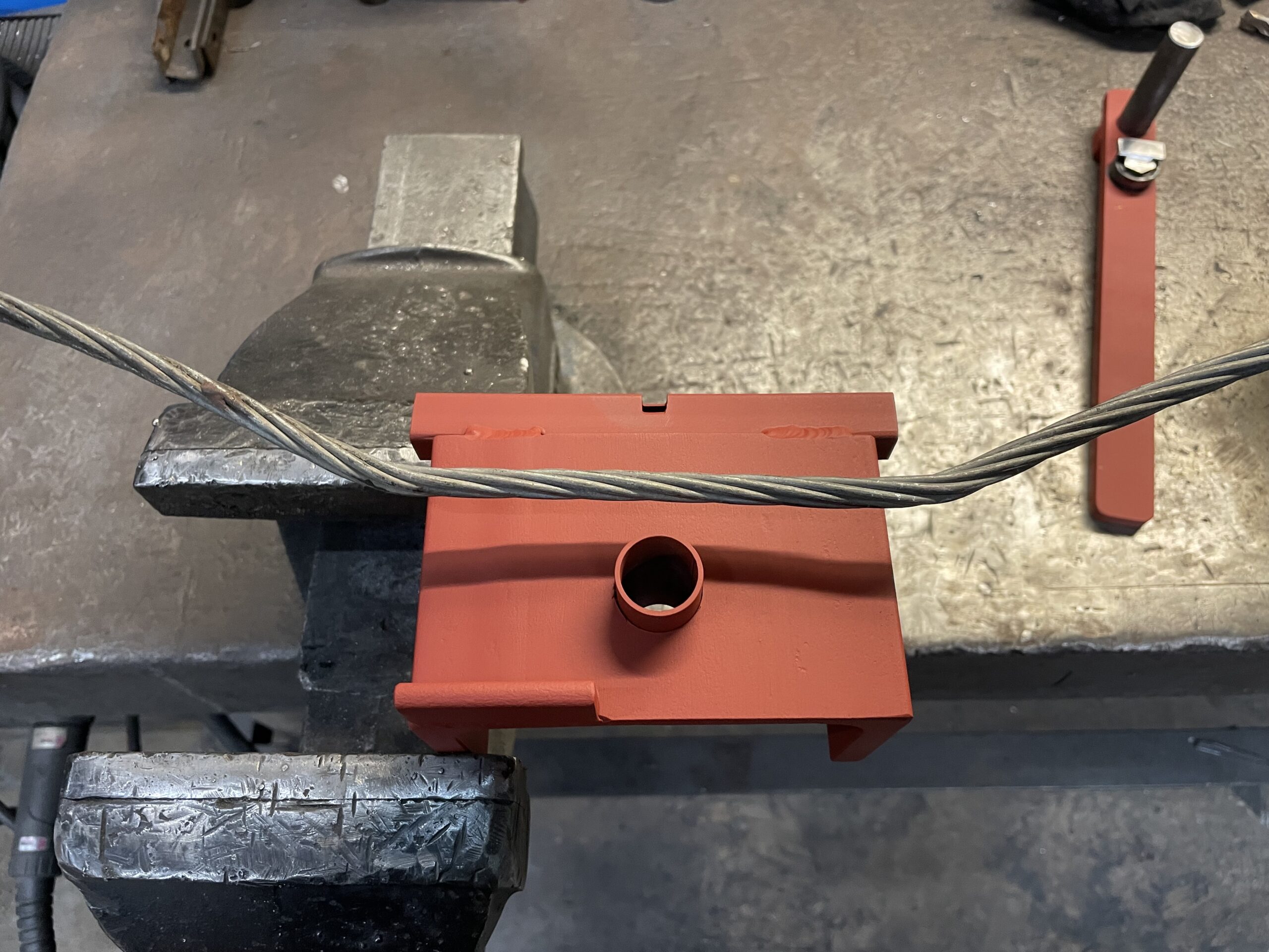
Below: The two pre-bends imparted into the spanwire.
Below: The resulting shape of the wire after removal from the tube.
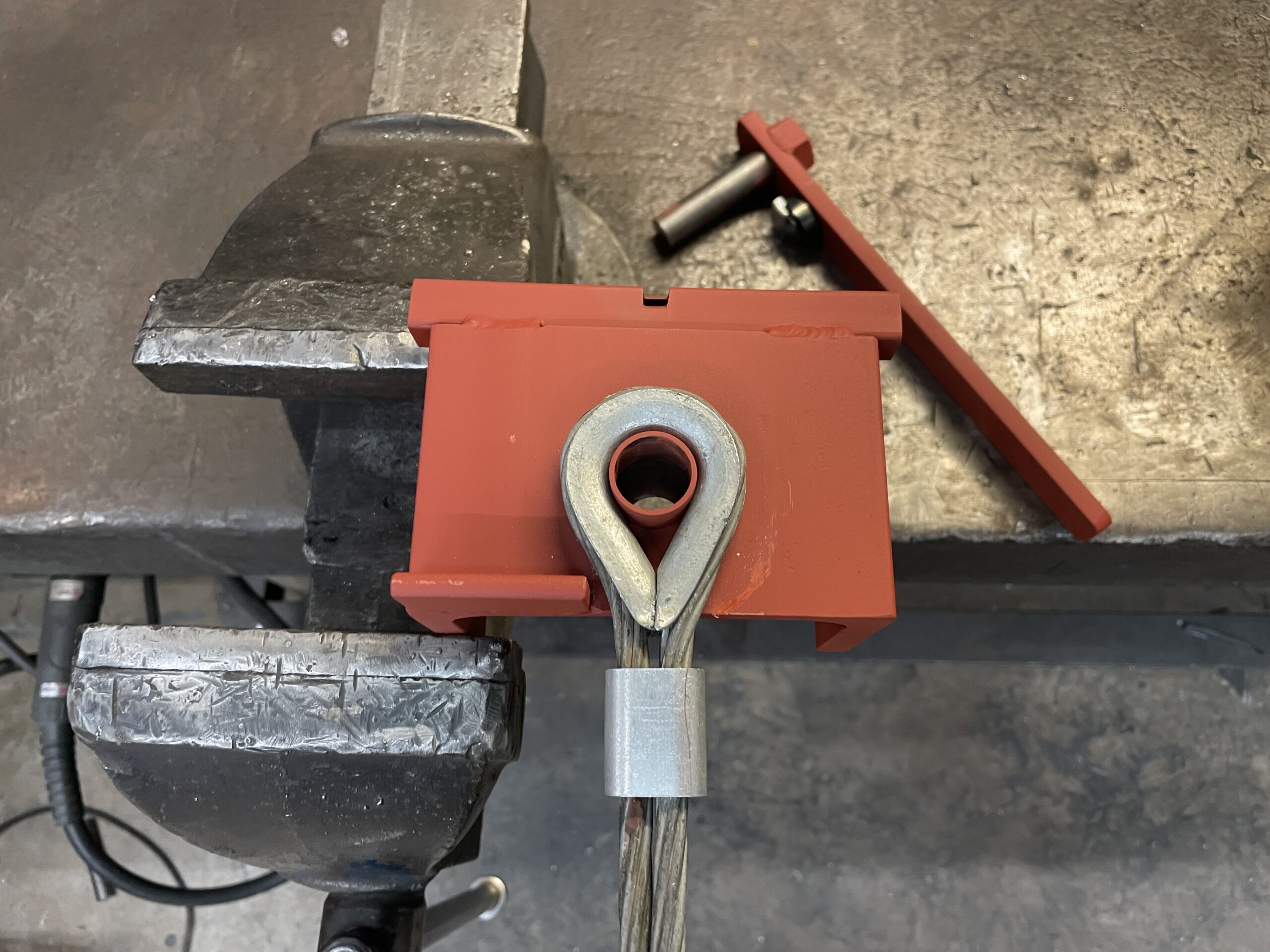
Below: The wire is then placed onto the top of the jig, with the eyelet in place and captive on the peg and against the upward angle, bottom left.
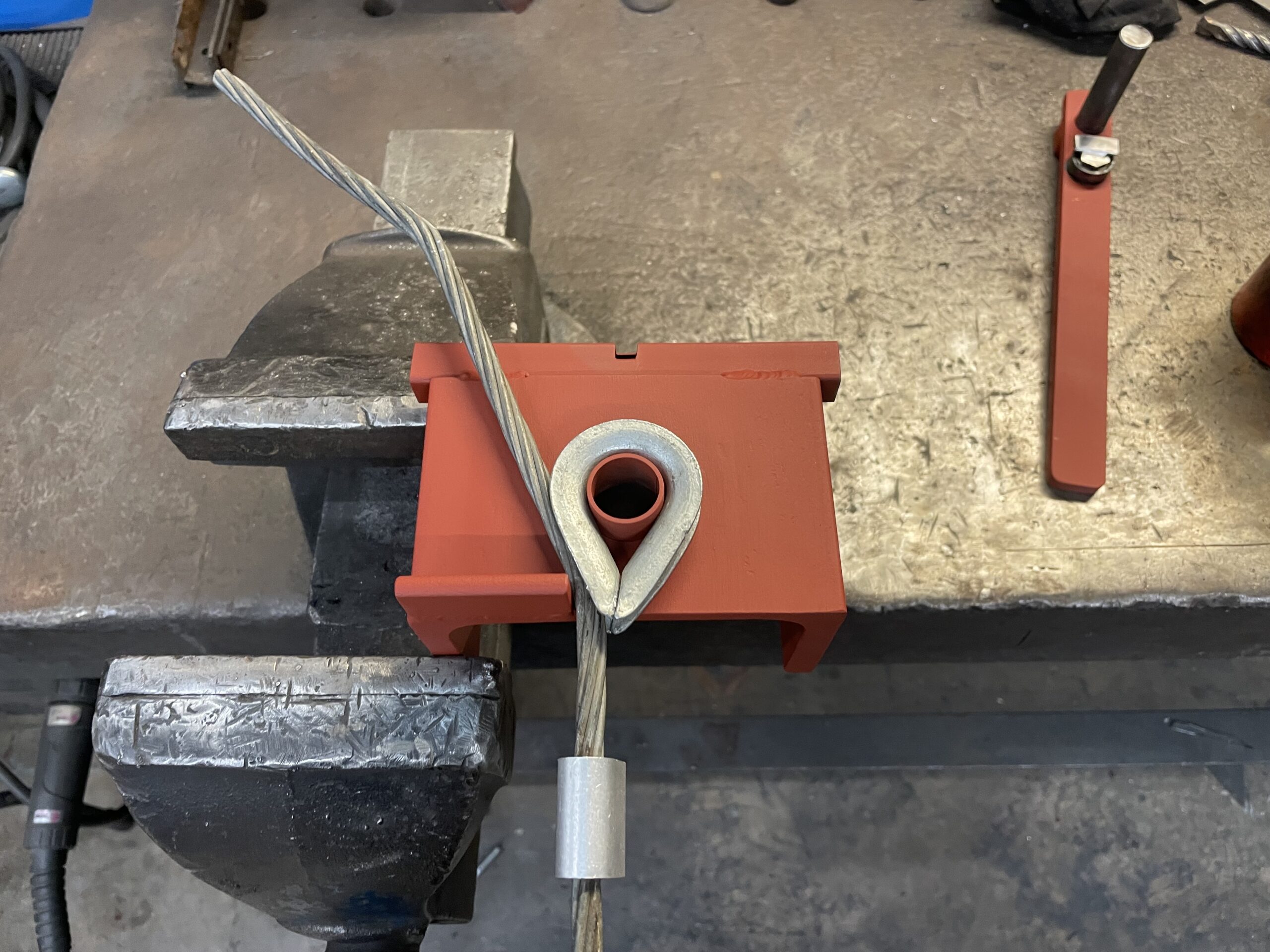
Below: A bolt is then inserted into the peg, with a bar that has a peg on the lower side of it (you can just make out the witness mark of this to the left of the bold head).
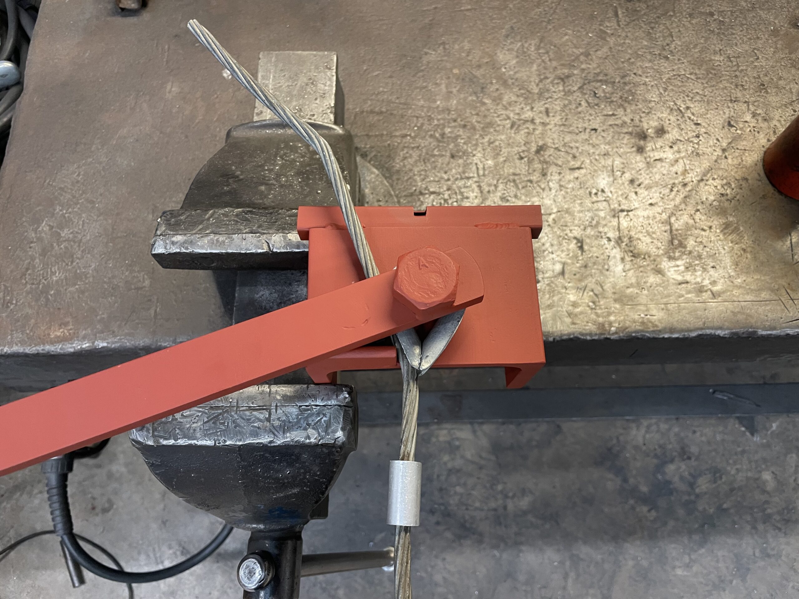
Below: The bar is then rotated about the bolt, with its peg capturing the wire and bending it around the eyelet. The pre-bent angle we saw earlier then aligns with the wire and allows the aluminium crimp to be neatly placed onto the wire and moved close to the eyelet to prevent the wire spreading at this point.
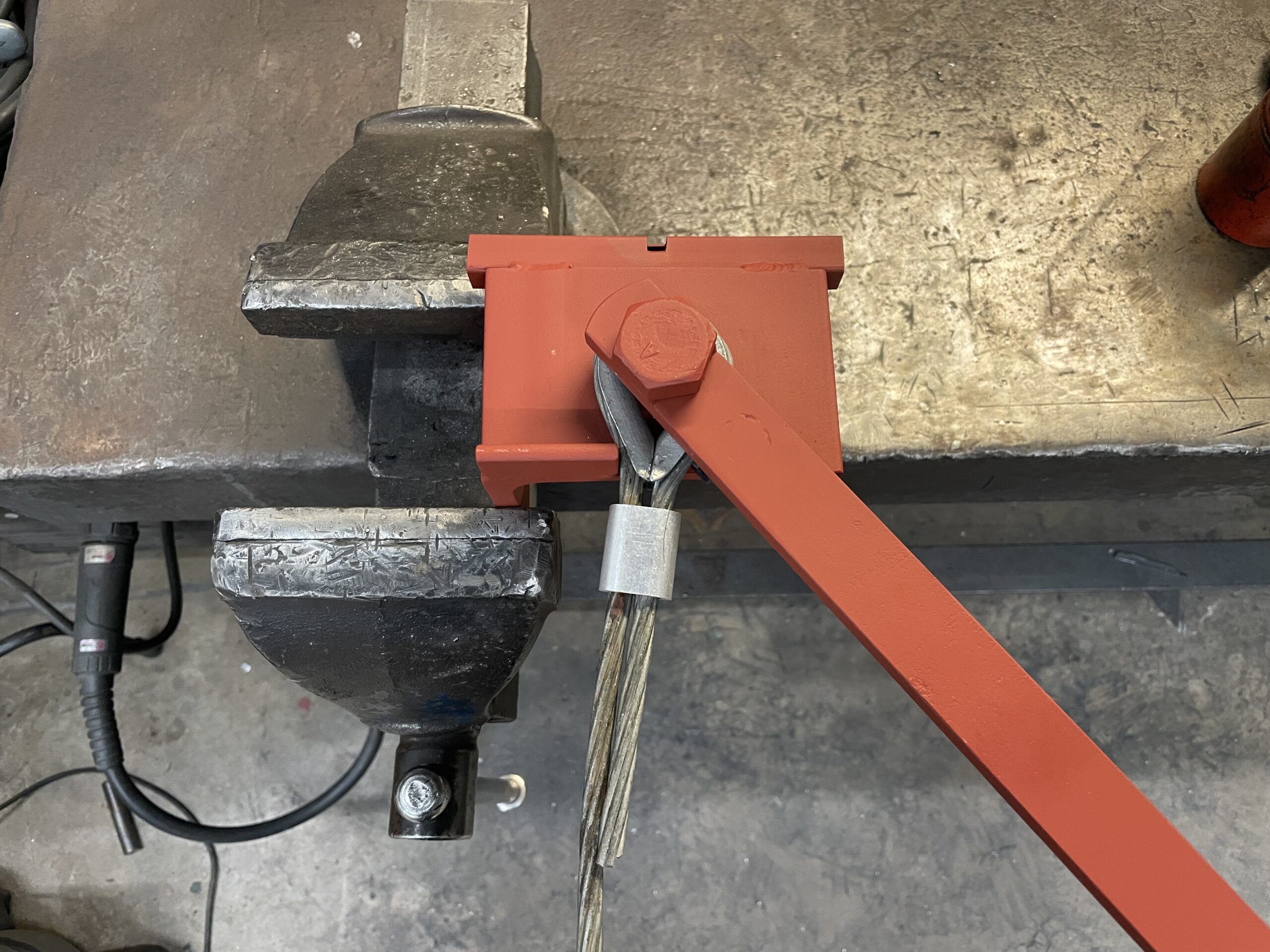
Below: The crimp is then secured using a manual crimper (a huge set of pliers), and the process is complete. The underside of the bending bar can be seen on the bench. This enables consistent and right bends to be created and a uniform standard of crimping to be applied. It also speeds up the process and gives a positive means of holding the workpiece.
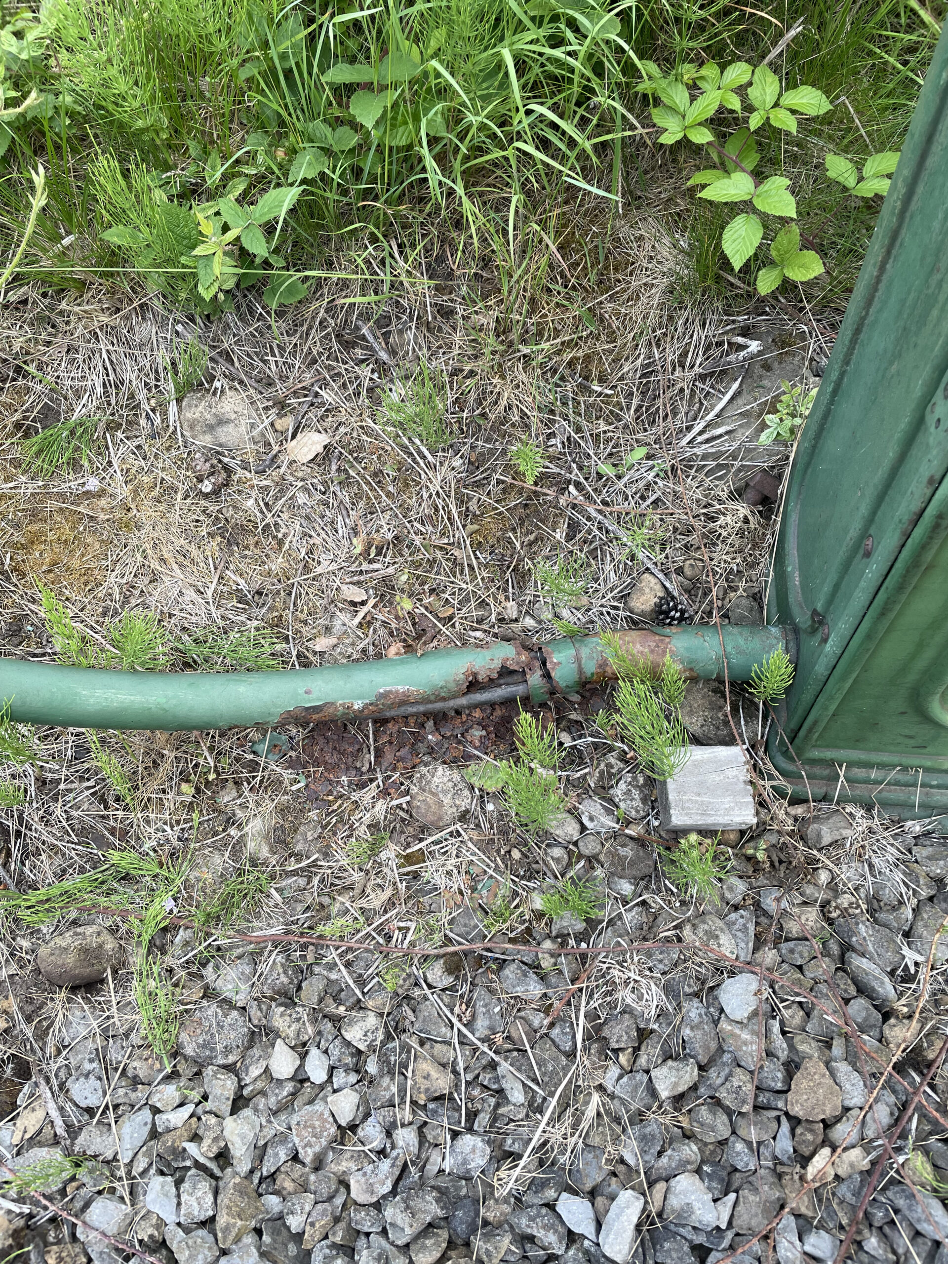
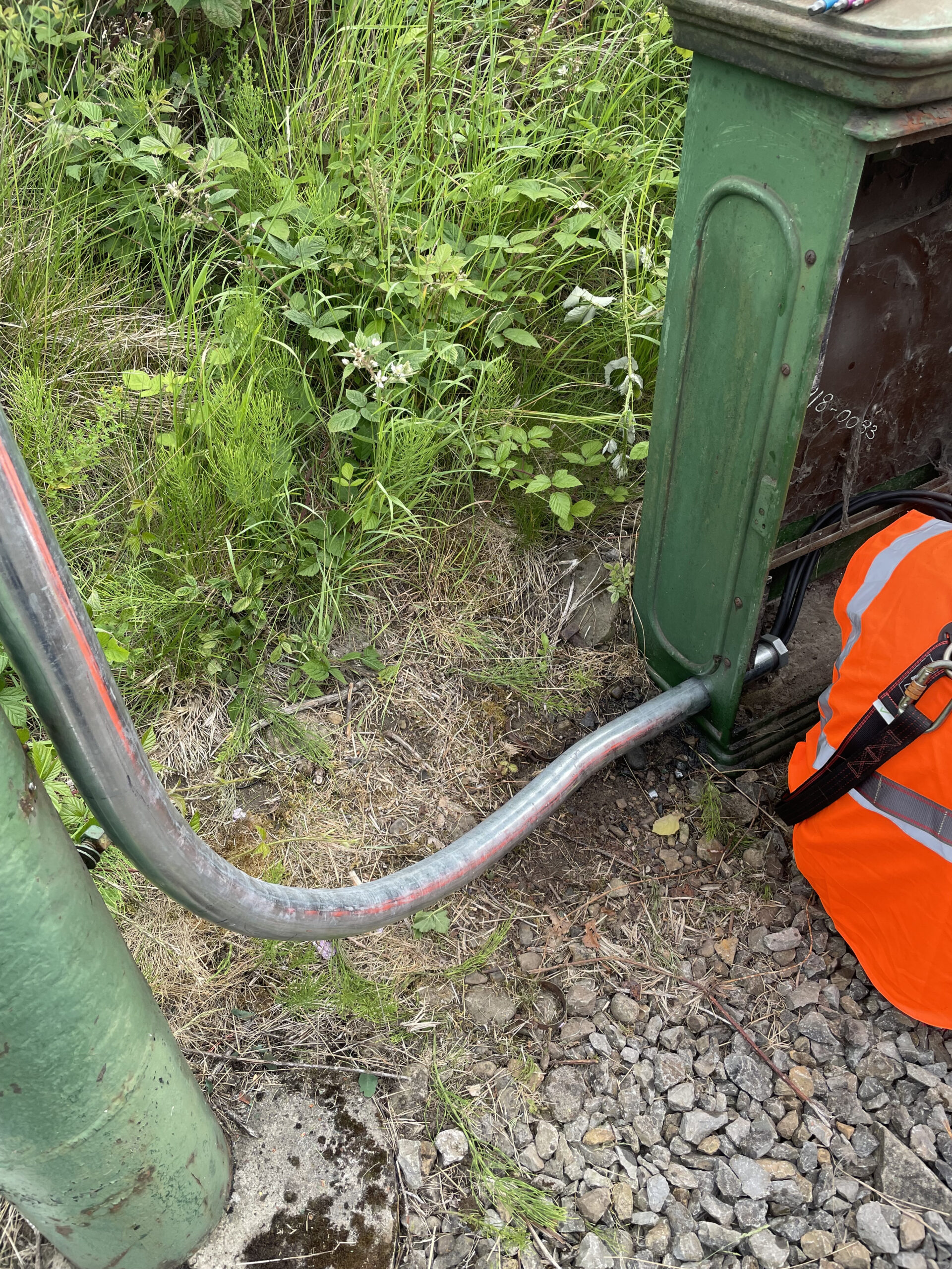
Below: Another job on the OLE was replacement of the pipe within which the cables run down from the overhead at the Section Insulator (SI) in the vicinity of the Welfare Hall. The cables run to a section box, within which is the mechanism that allows for sections of the tramway to be isolated at a local level, and retain other sections in a live condition for continued operation. The pipe within which these cables run, and are protected, had corroded badly at the point of entry to the section box, and so required renewal.
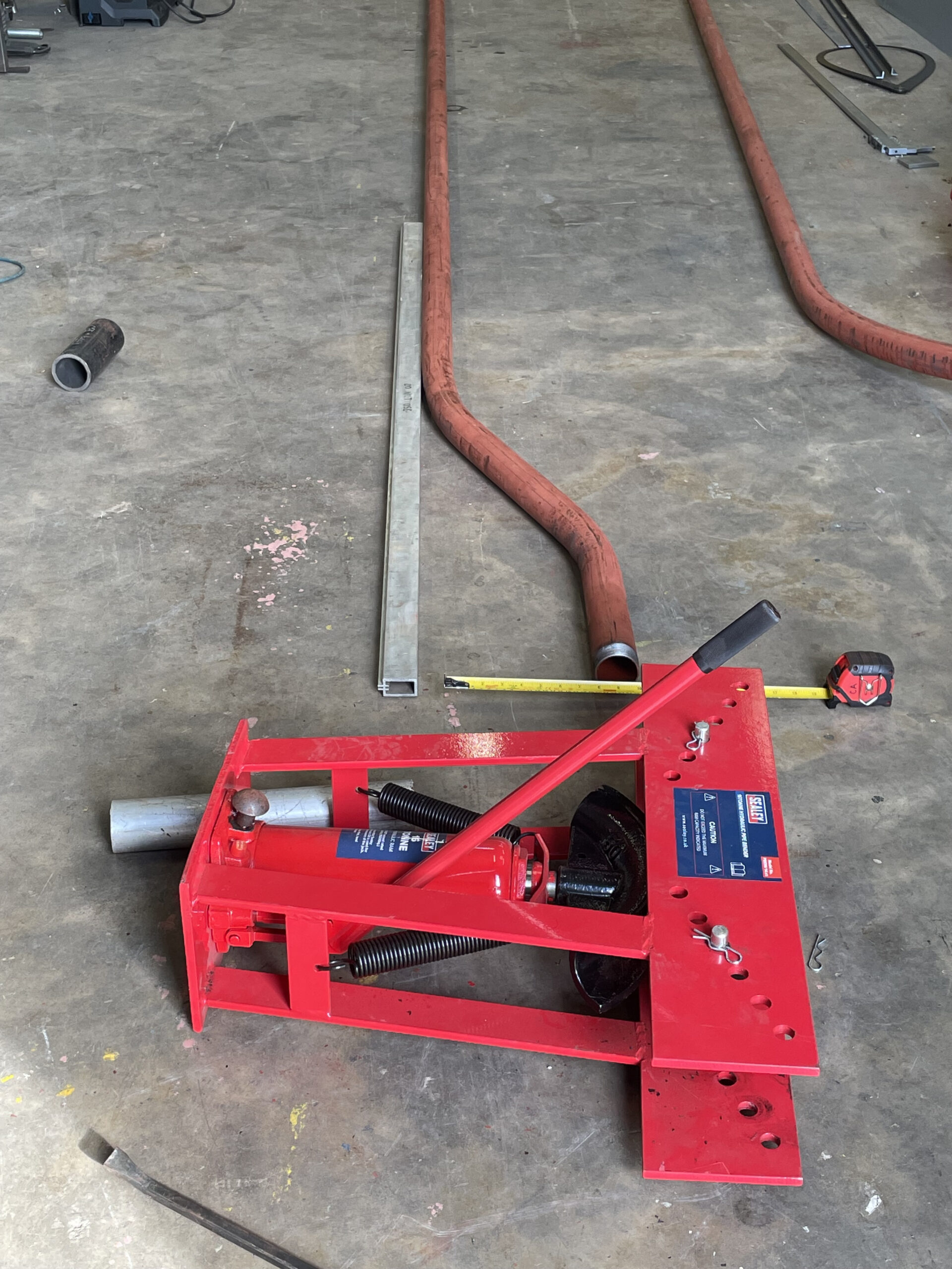
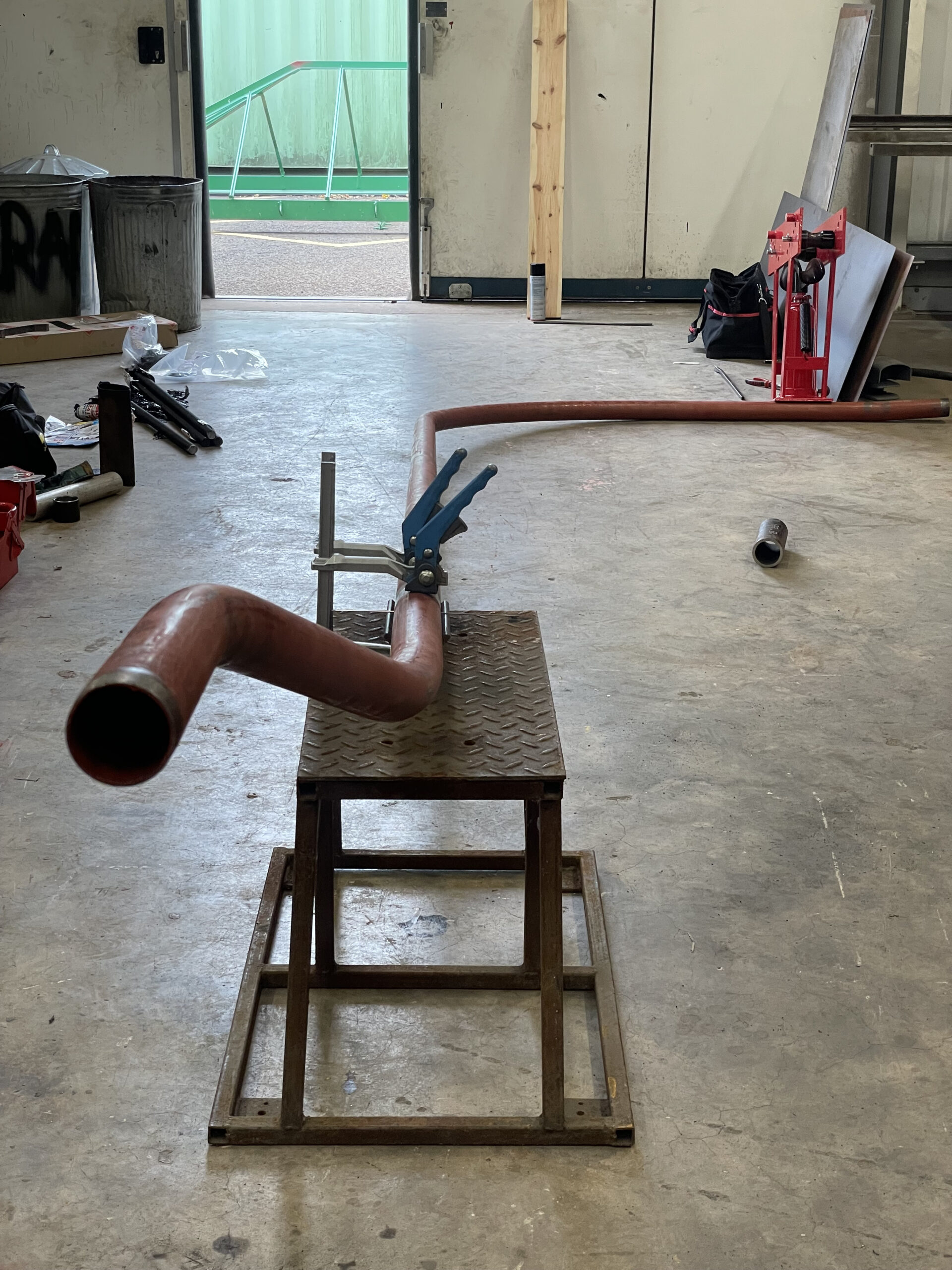
Below: The replacement pipework was prepared in the Fabrication Shop, after an on-site survey, and a hydraulic pipe bender was used to impart the required curves.
Below: Manuctured in sections, these were then welded together.
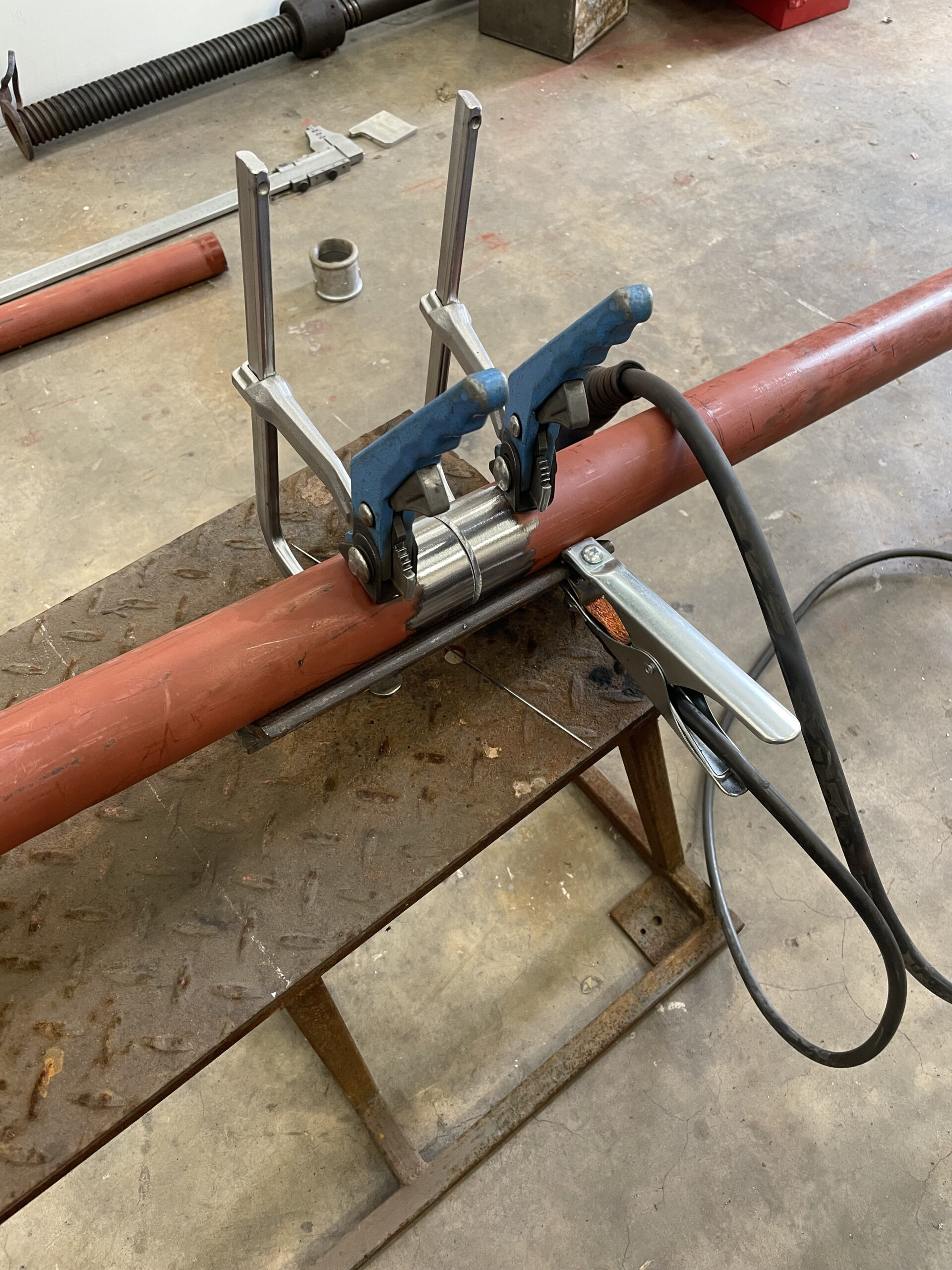
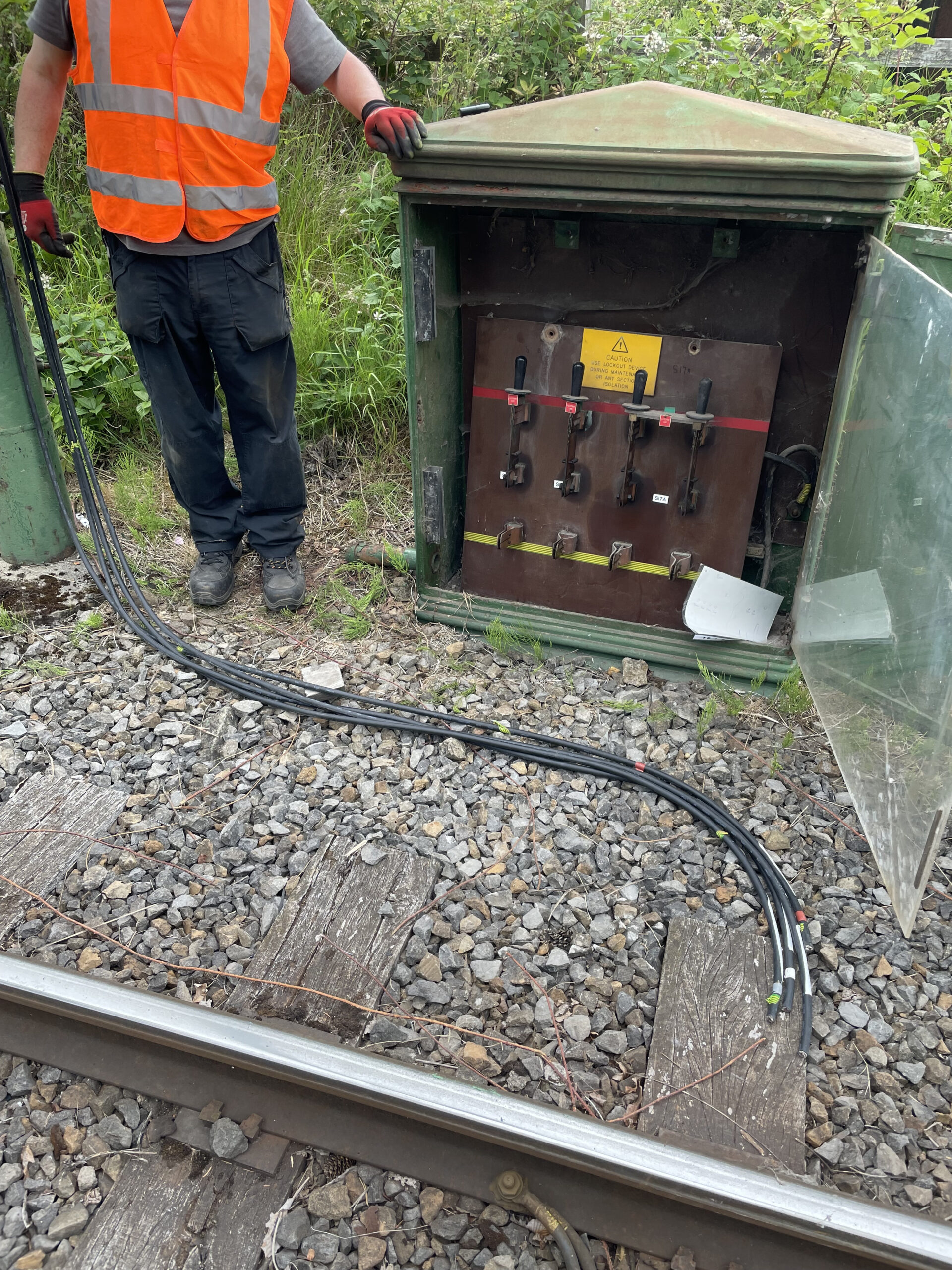
Below: With the old pipe removed, the wires were exposed and also replaced during this process. The interior of the section box can clearly be seen here. This section of line has two wires (both positive) for the Pockerley – Town and Town – Pockerley section (to enable the sub-station trip-gear to see a fault over the distance to this location). Therefore there are two sets of switches in this cabinet.
Below: With the new wires drawn through the pipe on the ground, the assembly is then lifted into place.
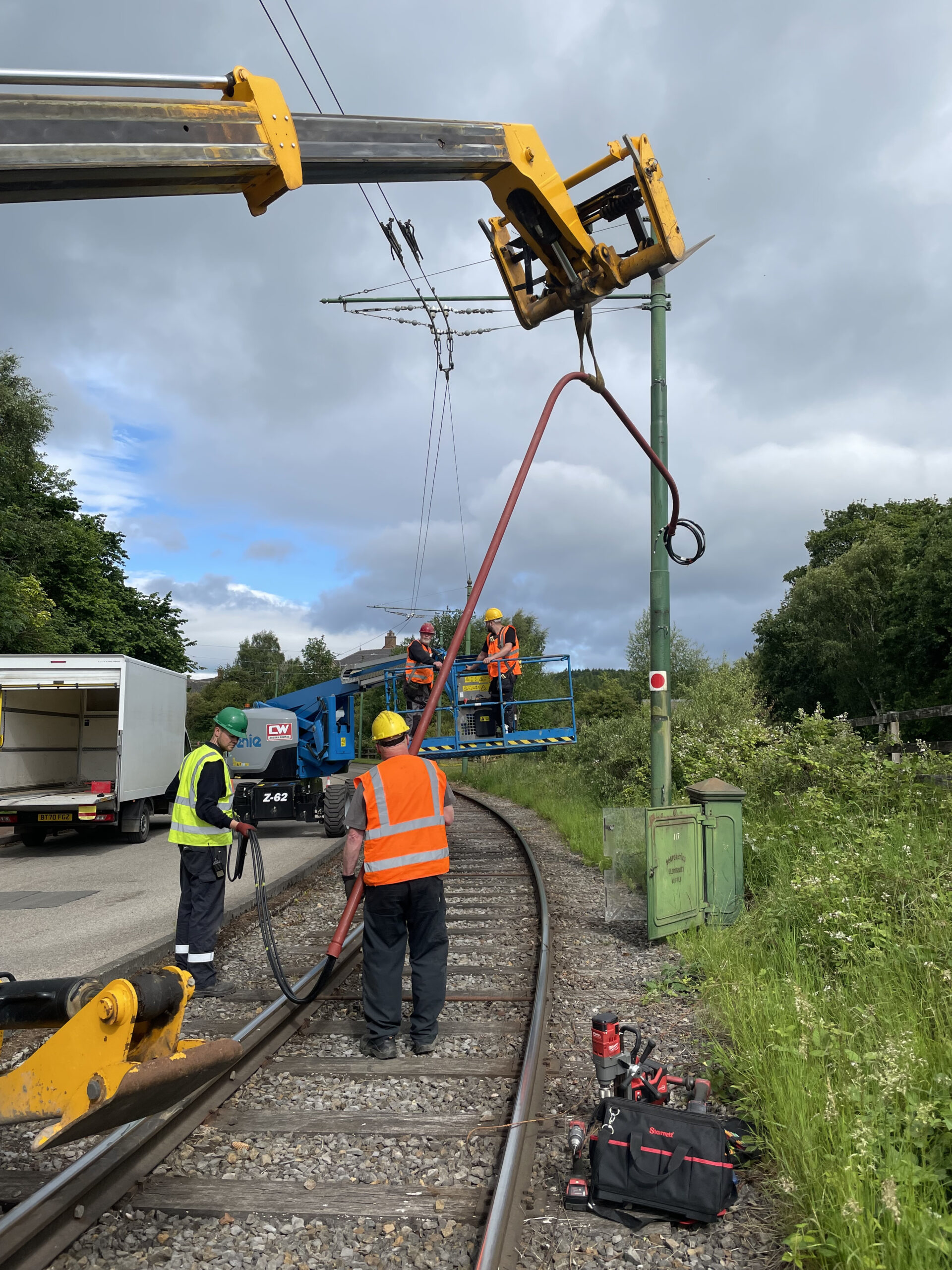
Below: With very specific dimensions to adhere to, the accuracy required can readily be appreciated in this view, showing the pipe entering the section box at the base.
Below: The wires could then be terminated on the board within the section box.
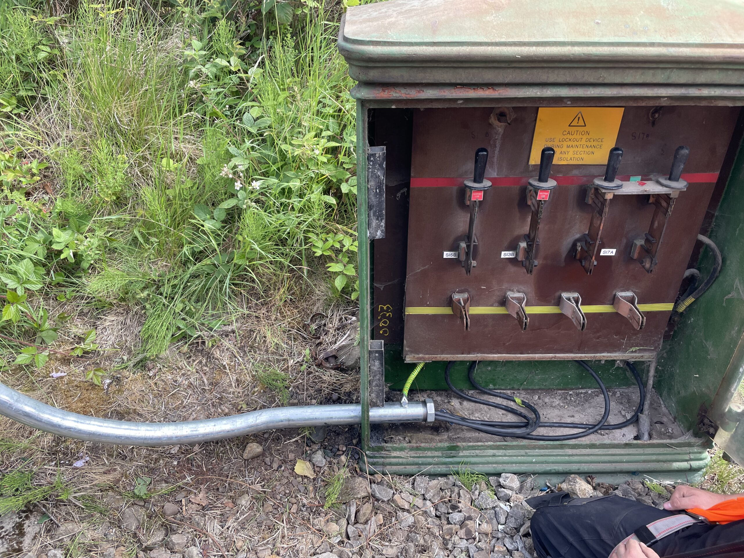
Below: The completed work – note the Section Insulators that are inserted into the contact wires, the two contact wires (both positive) and therefore the ability to be able to isolate sections of the Tramway whilst keeping other sections live. A plan for some traction pole painting is being formulated as some of the poles are in need of cosmetic treatment.

Below: A similar process was carried out at the section box at Foulbridge, again following the same principals as outlined above.

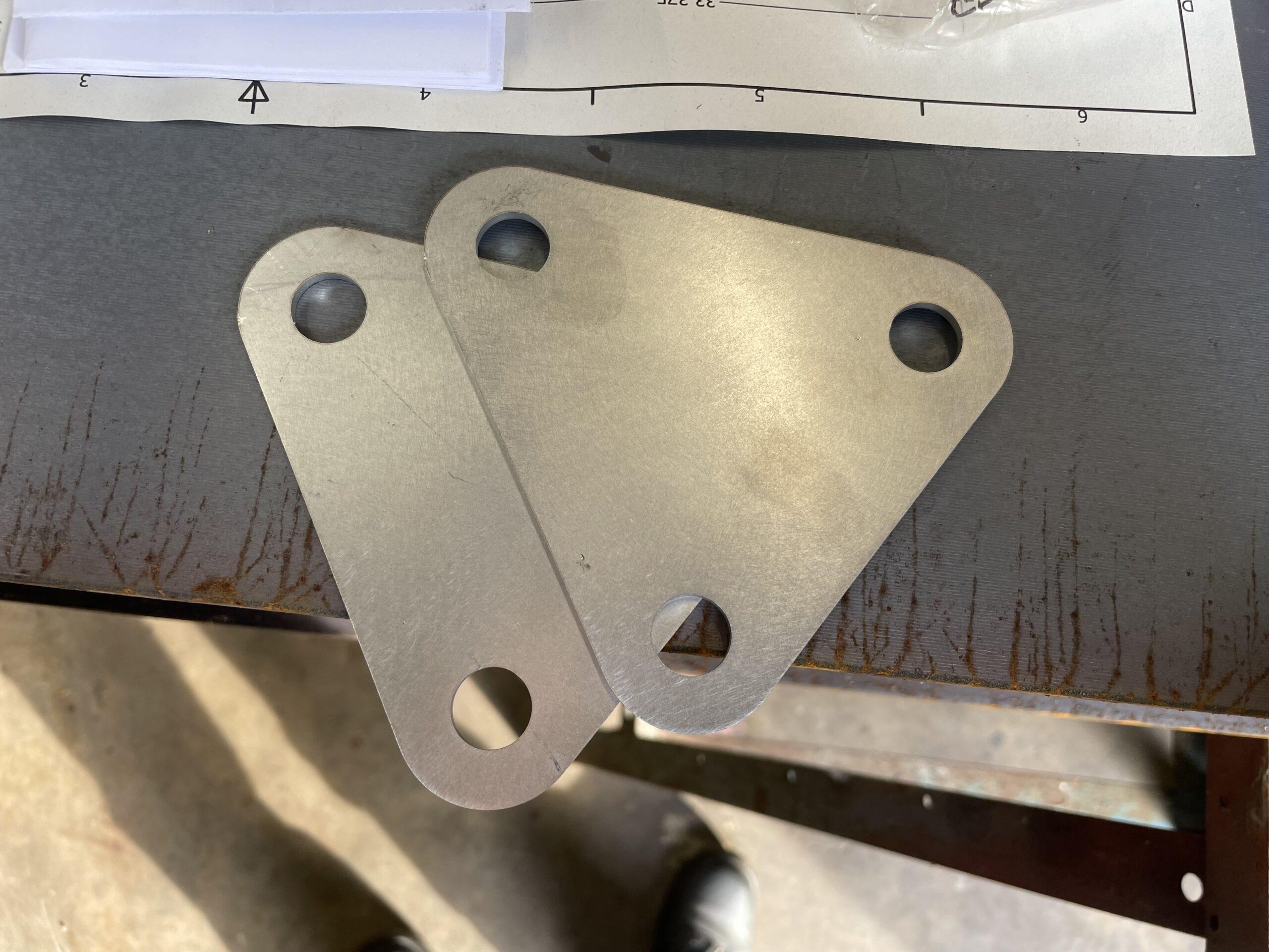
Below: As part of the process of replacement of spanwires, new clevis links have been designed and laser-cut from stainless steel (for longevity and future ease of dismantling). Here are examples of the two into one (or one into two) links.

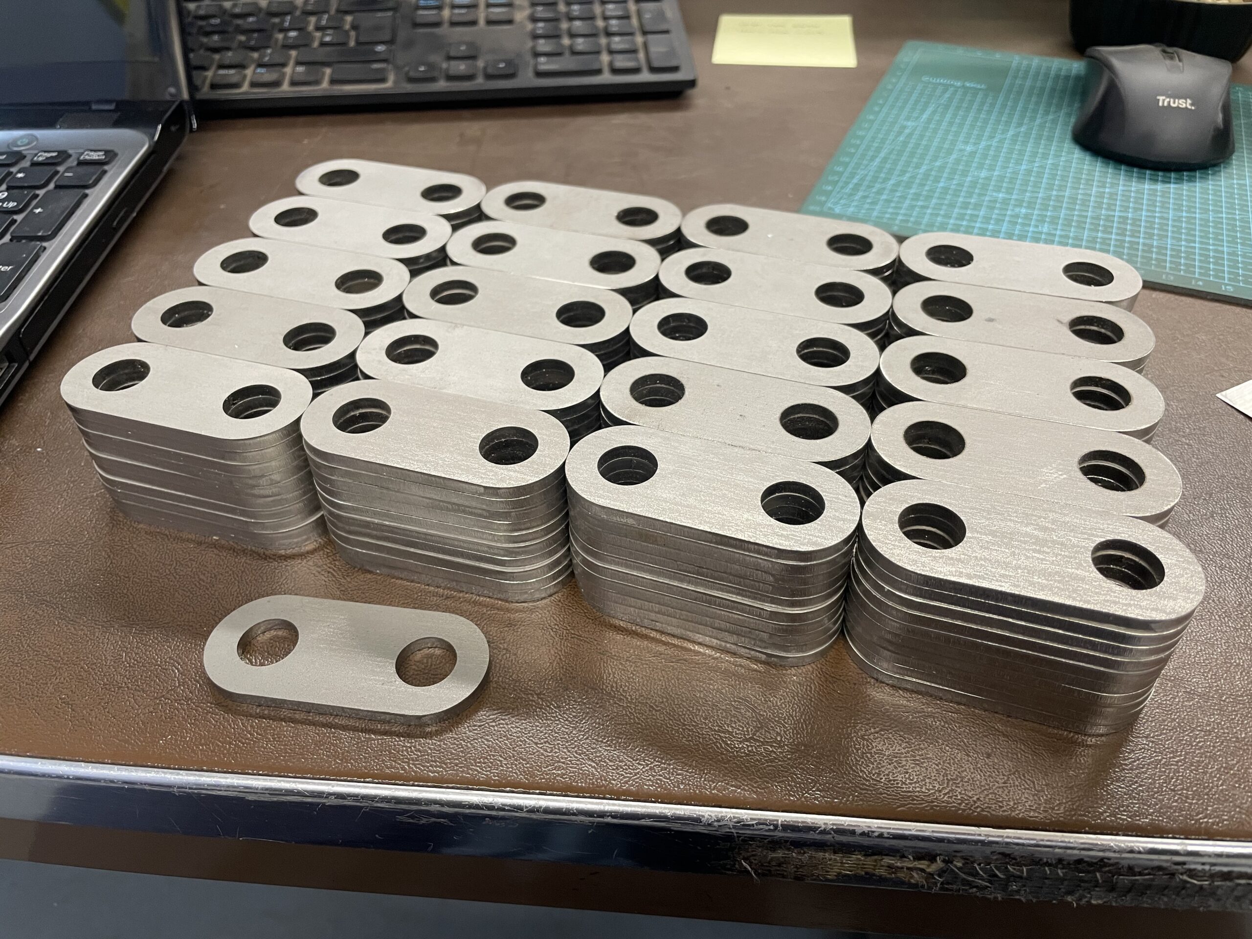
Below: Standard two-hole links were also procured (316 in total) which are paired when assembled into the span wires, again using stainless steel fastenings. Having these laser-cut by an external supplier is considerably cheaper than manufacturing them in-house and makes best use of the team’s time and expertise where it is required.
Below: The images in this section show what Chris and Dan have been designing and working on in collaboration with David who looks after the OLE. As an additional, non-tramway, example of the work that is carried out in the Fabrication Shop, this is a lamp post hatch cover that Dan made to fit one of the posts in Birch Wood when the ‘new’ period-style lighting was installed in the autumn.
Below: Moving to Tramway track now – this is a redesign of the spring mechanism that gives the point blades a positive return to their resting position after a tramcar has trailed them (and the wheels have pushed the blade across, against the spring). These units have been on the long-term list of desired work to the Permanent Way on the Tramway.

The Tramway is going to receive quite a lot more attention this winter, with rail welding to restore the contact faces on the curves outside the Bank planned, quite extensive re-sleepering to commence and more progress on renewal of components in the overhead. We also have new Ri60 grooved rails on order to replace a short section of track leading Town-bound from the loop at Foulbridge. This will enable us to create a larger bus turning circle for the Colliery route, enabling the use of larger vehicles and also removing the ‘turn’ from an area of visitor congestion adjacent to the bus/tram stop.
Miscellaneous
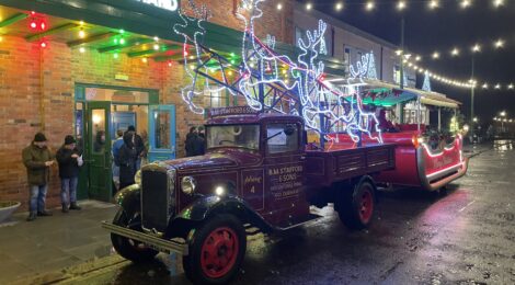
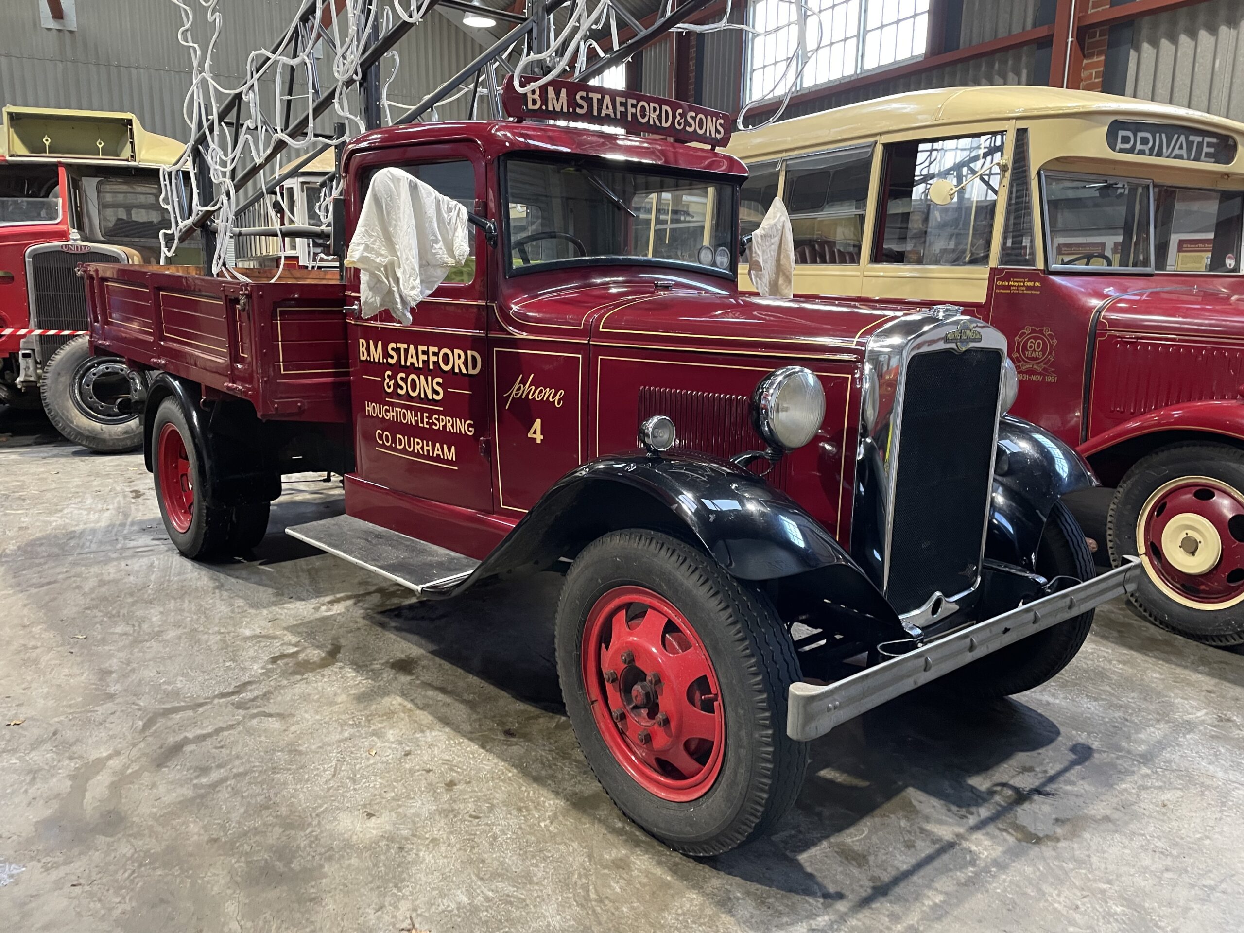
Below: At previous Christmas events we have seen Santa’s sleigh drawn by road steam locomotives and steam waggons, whilst this year he has this lovely Morris Commercial for motive power. This temporary resident has allowed us to compare it to our own Morris Commercial, and a plan is being formulated to carry out some work on the museum’s vehicle, including replacing the wings and carrying out some other cosmetic improvements as well as removing the van body and restoring it as a dropside lorry.
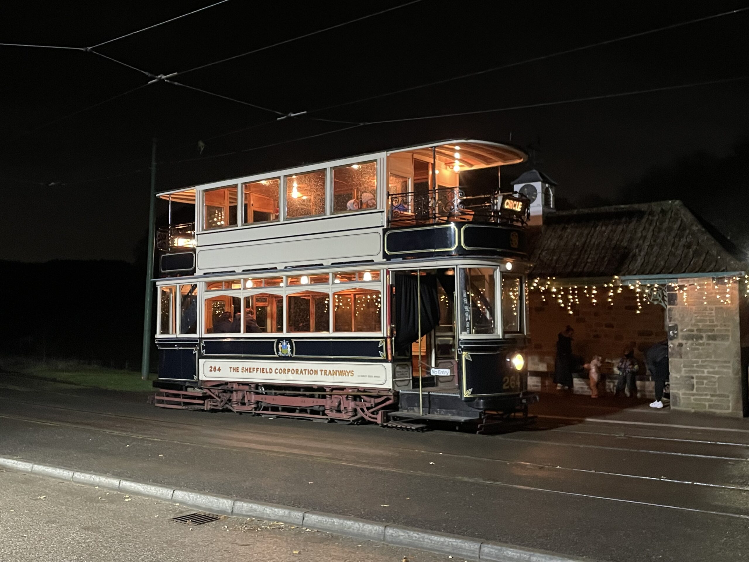
Below: The Christmas evening events are a good opportunity to see the trams and buses operating in the dark, with some interesting flood lighting effects at some locations around the site. This is Sheffield 264 at Pockerley, under powerful artificial lighting.
Below: 2025 has been a year of paint! Both of these vehicles have received partial repaints during the year, and the effect is very appealing and hopefully gives a very good first impression to visitors.
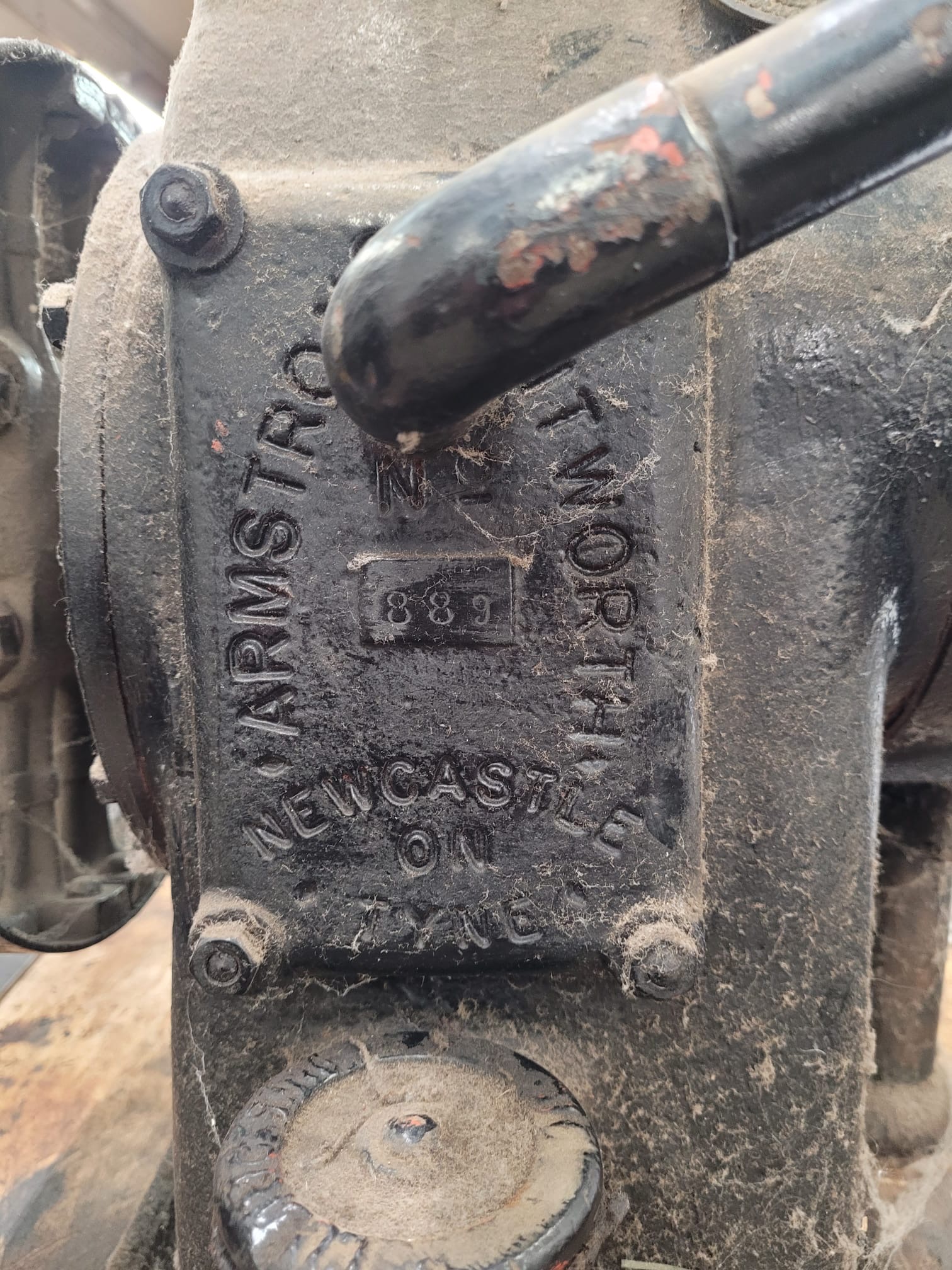
Below: As if there were not enough to keep the levels of excitement and interest high… Phil and Phil’s eyes were caught by this Armstrong Whitworth single-cylinder engine that has been on display in the garage for many years. With the interest in all things Armstrong Whitworth and internal combustion, it was decided to remove this to the machine shop to explore the possibility of making it work, as a Christmas project. Probably dating from the early 1920s, when AW were turning their efforts from war-work to domestic engineering, the quality of engineering is very high and the research that is taking place agains the physical work is revealing some interesting elements about what was a very local manufacturer to the museum.
It is missing its flywheel and appears to have been shotblasted and painted at some point in the past (as the sump was full of sand) but a flywheel has been located for it (ex Lister) and a suitable means of water cooling will be devised. Its one of those projects that is almost as much about learning about the object as it is creating a new exhibit, but I must admit to already trying to think of a suitable application for it when it’s done!

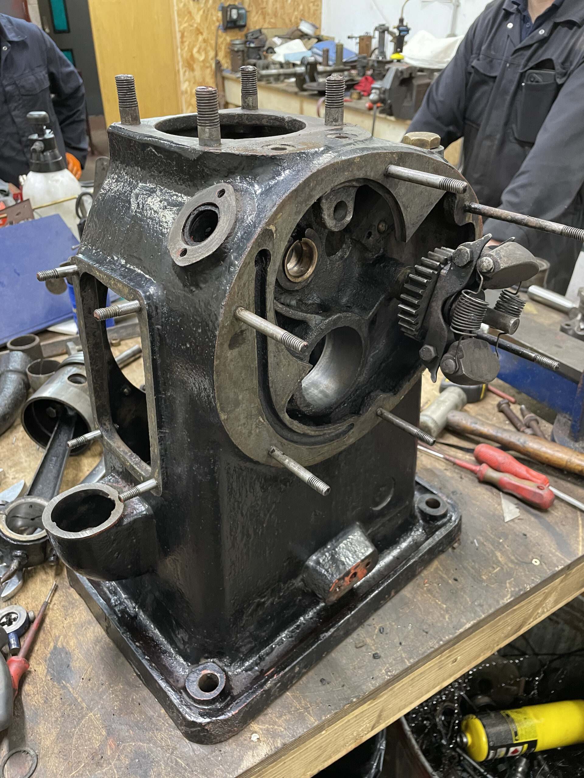
Below: The engine was dismantled within a few hours and when this photo was taken, new crankshaft bearings were already in production.

Hopefully readers will have enjoyed this extended post – which shows some of the diversity of work, and skills and talent applied to it, in what is a relatively small team. It also gives something of an insight into what it takes to keep the transport system operational, and to ensure that it gives the very best heritage experience but still remains compliant and meets 21st century safety standards. It also shows how the use of Computer Aided Design, laser cutting and 3D printing can ensure we make the most of our resource and embrace modern technology and manufacturing methods where these are appropriate.
Join us again in 2026 for more of the same!
Photos in this post by Chris Armstrong, Duncan Ballard, Phil Doran, Matt Ellis, Paul Jarman, John Marshall, Phil Smith, Sam Telfer, Ben Wilson and Ash Wiseman.


Samsons flywheel was bored by contractors and held as Fowles did on their engines, that is with a pegthrough the crankshaft. I recall the flywheel was not overtight when first fitted!
Maybe sleeveing? good luck Matt, Dave young