
Days in the life No.1: RHEC Technician (Engineering)
Here is the first of what will be an occasional series looking at the various members of the team and some of their activities within the Transport & Industry/Site Support teams that make up one part of the overall Museum establishment. As the blog is focussed on these subjects, they will cover familiar territory, but in rather more detail than usual. So we start, alphabetically as it happens, with Chris Armstrong, the RHEC Technician focussed on engineering. Chris keeps his own photographic diary – from where these images are taken (with due acknowledgement).
Gallopers
Running a fairground rid from 1893 in continuous daily use (far more than it ever did when in its showland ownership) is a challenging task and the RHEC team invest a considerable amount of time in its upkeep, not to mention considerable investment generally in its maintenance.
Below: Last winter the Gallopers received new steps – to a revised design as we do not travel the ride other than within the Museum. New box section step frames were made, requiring jigs, much repeated cutting then repeated welding to form the sections we wanted – lightweight and very strong.


Below: This view shows the work on the little end of the organ engine. The rest of the engine has subsequently been rebuilt subsequently.

Below: Mention of the leaking stud within the centre engine firebox may be recalled. The stud is one of a set that carry the brackets supporting the firebars. Renewal of such would usually be fairly routine except for the very restricted access to the inner firebox of this engine – which is barely a foot from back to front and with half of this beneath (with the ash pan removed). So no chance of climbing in! Chris therefore manufactured this jack screw and drill device (suitably named!) to drill out the hole after the old stud was burned out.

Below: A two man effort with David Grindley plus mirror enabled Obi-Wan to work backwards towards the operator and into the plate. The ring spanner movement was similarly restricted ensuring that the actual work was fairly lengthy process. This is the view down into the firebox through the firehole door showing just how confined a space it is.

Below: The new stud – stepped to take account of the larger diameter of the new hole (which as well as being drilled also had to be tapped).

Tramway Rail
In tandem with Darren and Mark, the PW team Engineer and Technician, further welding work has been carried out on the curves on the tramway within the Town area. The reverse curves are a nightmare from a maintenance point of view and were designed in this way in order to create a visual block within the Town area, though an alternative route would certainly have been possible! Re-railing has already taken place in the past, but welding of these rails is now required and this has been underway in recent weeks.
Below: A view along the rail showing the wear in the running head. This produces a corresponding wear on the opposite rail check-rail (which is not supposed to act as a running check rail, more to keep the groove clear of debris/road surface). These rails have been replaced within the last five years but are subject to continued wear in operation. The outer rail of a curve is called the ‘high’ rail, the inner rail being the ‘low’ rail.

Below: The start of a long job – beginning at 5am and working through until nearly midday.


Below: 150 welding rods later and the rail head has been built up. Darren and Mark then followed along using a rail mounted grinding wheel to establish a smooth and continuous profile of the correct dimensions.

Below: Late morning and the first tram tests the repair. Frustratingly for the team, this is work that will have to be repeated in a few years time, though there remains an ongoing action on our minutes to progress various options for tramcar wheel flange lubrication – the challenge being to lubricate without leaving a deposit that is hazardous to pedestrians. Work on the road surface in this area is also on the list of actions to follow up.

In the workshop
Below: The work on Sunderland 16 was fairly well covered on these pages, but here is a reminder of the extensive work that went into the overhaul and reconstruction of the truck for this tram, which now runs beautifully.

Below: There is also ongoing work on components for the depot yard overhead wiring – a crossing being seen here. Like railway track, the trolley heads on trams and trolleybuses encounter pointwork at junctions, known as ‘frogs’ and these are also switchable – you will sometimes see the conductor pulling a handle on an adjacent traction pole to set these routes.

Below: Here is part of the overhead frog – in the raw cast stage and partially machined.


Below: The before and after stages – the teeth seen being cut (above) engage with the castings seen at the bottom of the photo, these being the components which switch the frog blades (and therefore change the direction) and which are assembled from interlocking cranks and pull levers as shown here.

Below: A more general repair carried out is illustrated by the patch inserted into Locomotion No.1’s chimney, subsequently being dressed and painted and now more or less indistinguishable.

Rambler
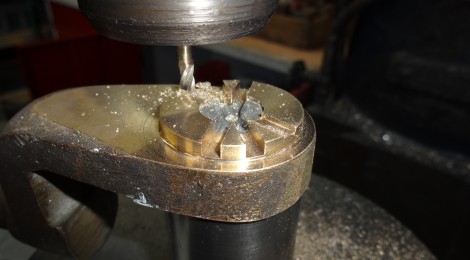
Below: Fowler steam roller 18877’s routine inspection revealed the need to carry out some work on the tubeplate washout plug, which was observed to have a poor thread and step on the plug. In keeping with recent tradition, the repair whilst simple is fairly inaccessible, being in the smokebox behind the front rolls. The first photograph shows the hole being reamed out – oversize to the original in order to cut a new thread cleanly. The tubes either side of the plug hole have blanks fitted, for which purpose will shortly be revealed…

Below: The plate in the middle has a hole in the centre and the tapered tap is fitted through this. The plate is welded to the two blanks, slipped into the adjacent tubes. In the foreground is the tool used to jack the tap into the hole, as both are rotated, the plate ensuring the tap enters the hole to start its cut absolutely parallel and without wandering, this being turned to cut, whilst the contraption behind produces the forward thrust to propel it forwards. Neat!

Below: A close up of the tap and tapped hole. This is a tapered arrangement into which the tapered plug (currently being manufactured for us) is inserted and tightened until tight.

I hope this insight is of interest to readers and shows in a little more depth than normal the work behind a few lines reported on this site. Over the coming months I intend to cover some of the other roles carried out by the staff within this department and which I hope will be similarly informative for the several hundred who now follow the blog.


Recent Comments