
Transport & Engineering Diary October 2026 Part 2
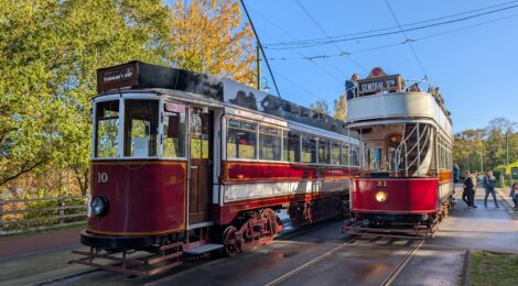
The big news for the end of October is the re-entry of Gateshead 10 into passenger service. We intend to make a bit of a fuss of this next month (this being the 125th anniversary year of the introduction of electric tramcar services in Gateshead), but this week being half-term and Halloween, the focus is on the more commercial activities on site, that are a significant element of our income at this time of year. The tram has completed a fairly extensive amount of mileage out of hours, including loaded tests. The Transport Operations Manager (Luke) has implemented a training and assessment scheme for Gateshead 10 given how long it has been out of service without any of our crews operated it within the last decade. As more crews are signed off on the tram, it will become a regular (I hope!) member of the working fleet once again. It has been a lengthy project, with many challenges (not least the discontinuity for the team members working on it) including a global pandemic and numerous technical challenges to overcome. We shall return to this subject in a future post…
Gateshead 10
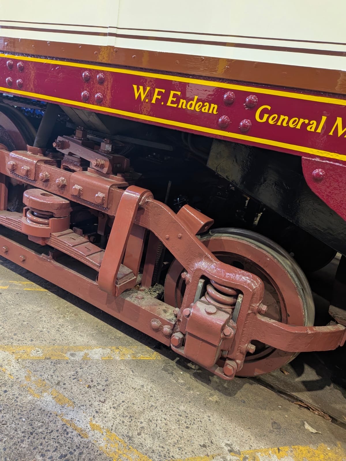
Below: During the rebuild of Gateshead 10, the opportunity to fit wheel flange lubricators was identified – part of a renewed attempt to mitigate against flange wear (side cutting) and gauge corner wear on the rail. Sam took up the challenge and the first stage was to identify a suitable location for the lubricators to be installed on the bogies. This drawing enabled the experimentation to be carried out virtually, before committing to a 3D printed version and the the final production prototype.
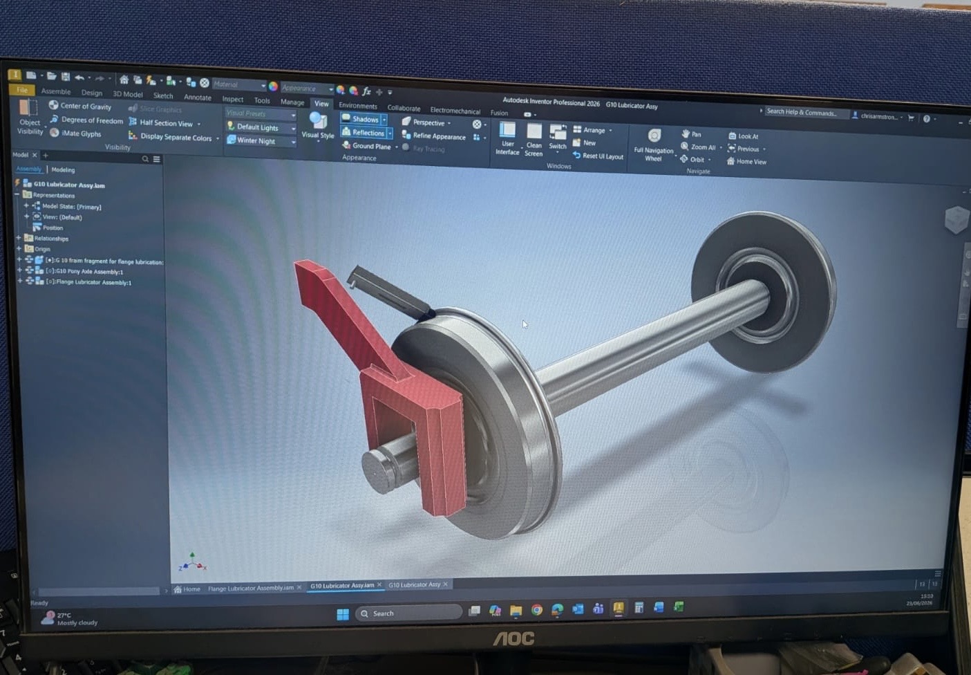
Below: The software will produce a template for the bracket to be cut out in the flat, making its manufacture (in steel) much easier.
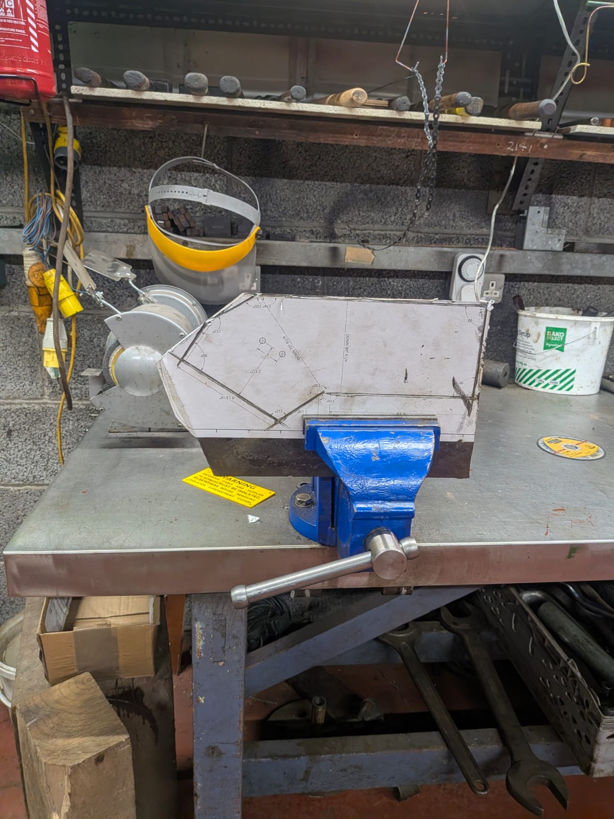
Below: The brackets, that both hold the lubricator to the bracket and the bracket to the bogie frame. The lubricator itself consists of a spring-loaded graphite cartridge, which targets its properties into the root of the flange, where side cutting occurs and is the most detrimental wear that occurs with tramcar tyres.
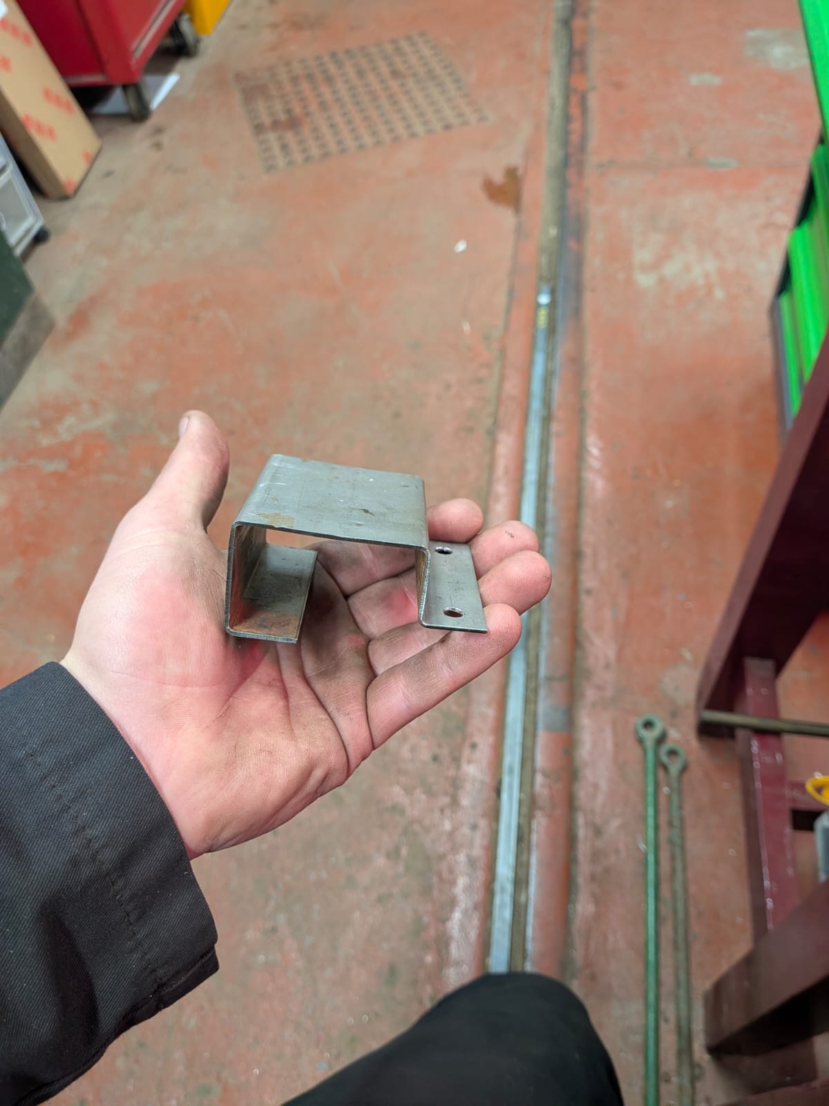
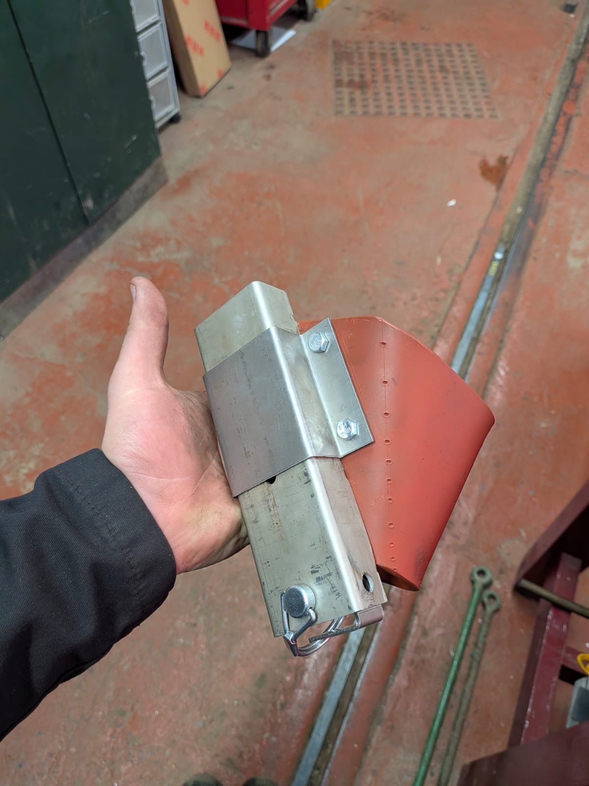
Below: After painting and final installation, the lubricator is fairly unobtrusive. We will now observe the results before rolling out the same fittings to other tramcars.
Sunderland 16
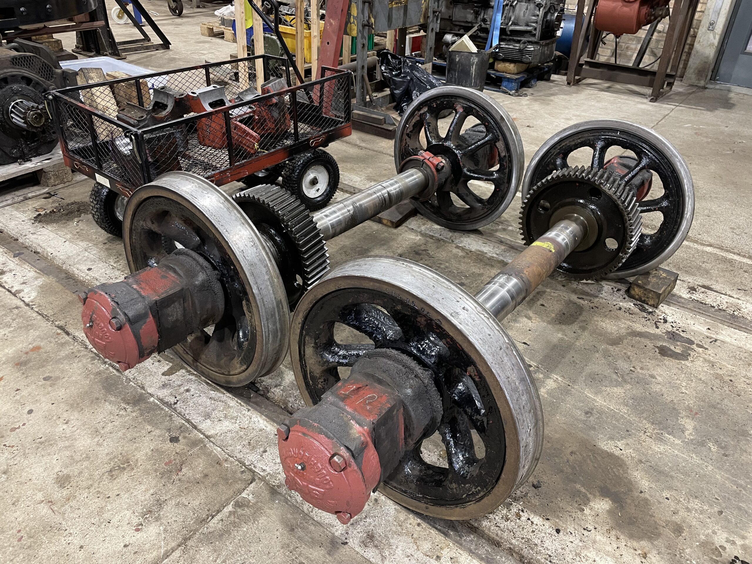
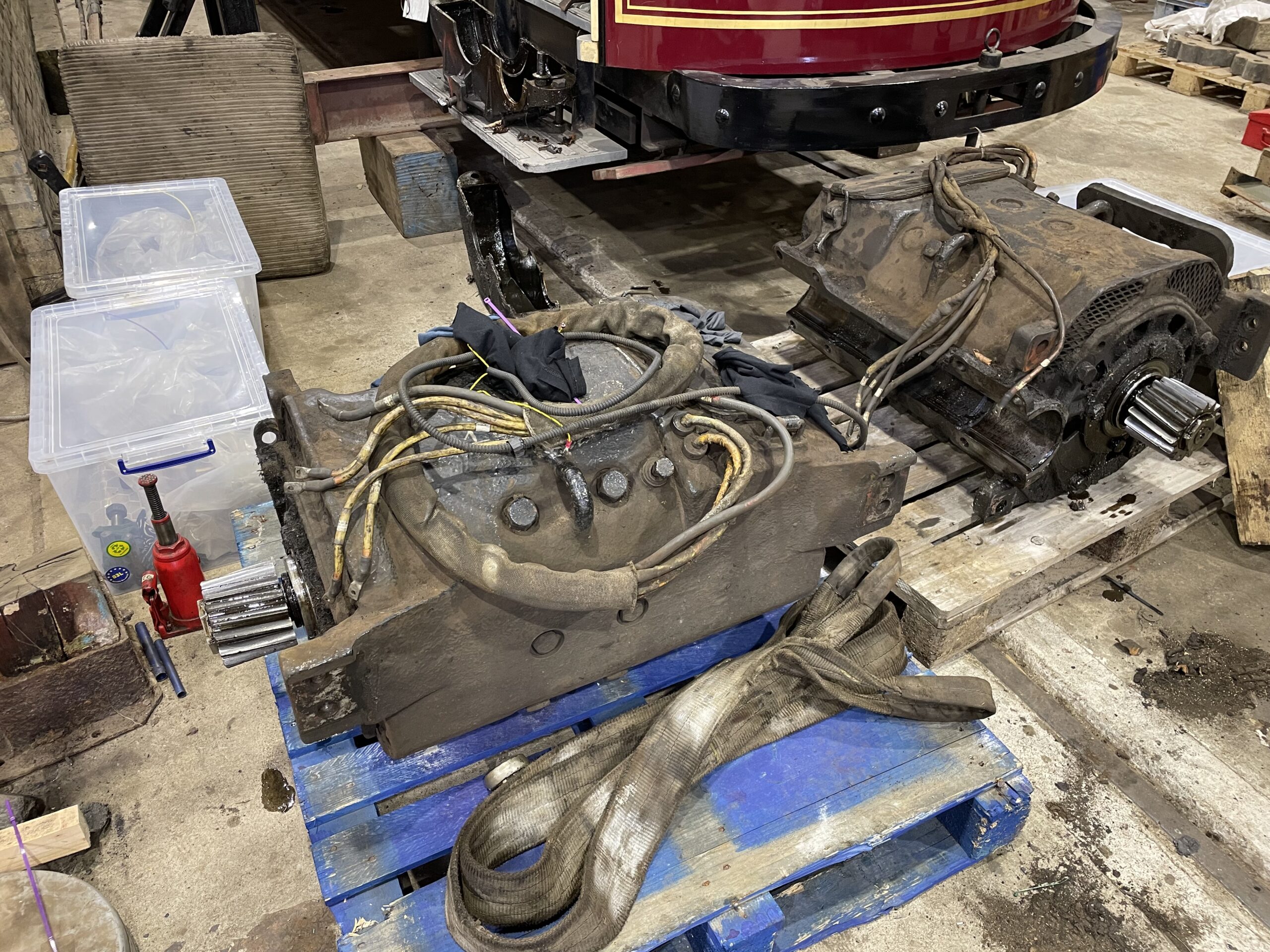
Below: The wheelets have now been removed and await dispatch to the contractor for re-tyring. The motors are similarly ready to go to a contractor for inspection and overhaul.
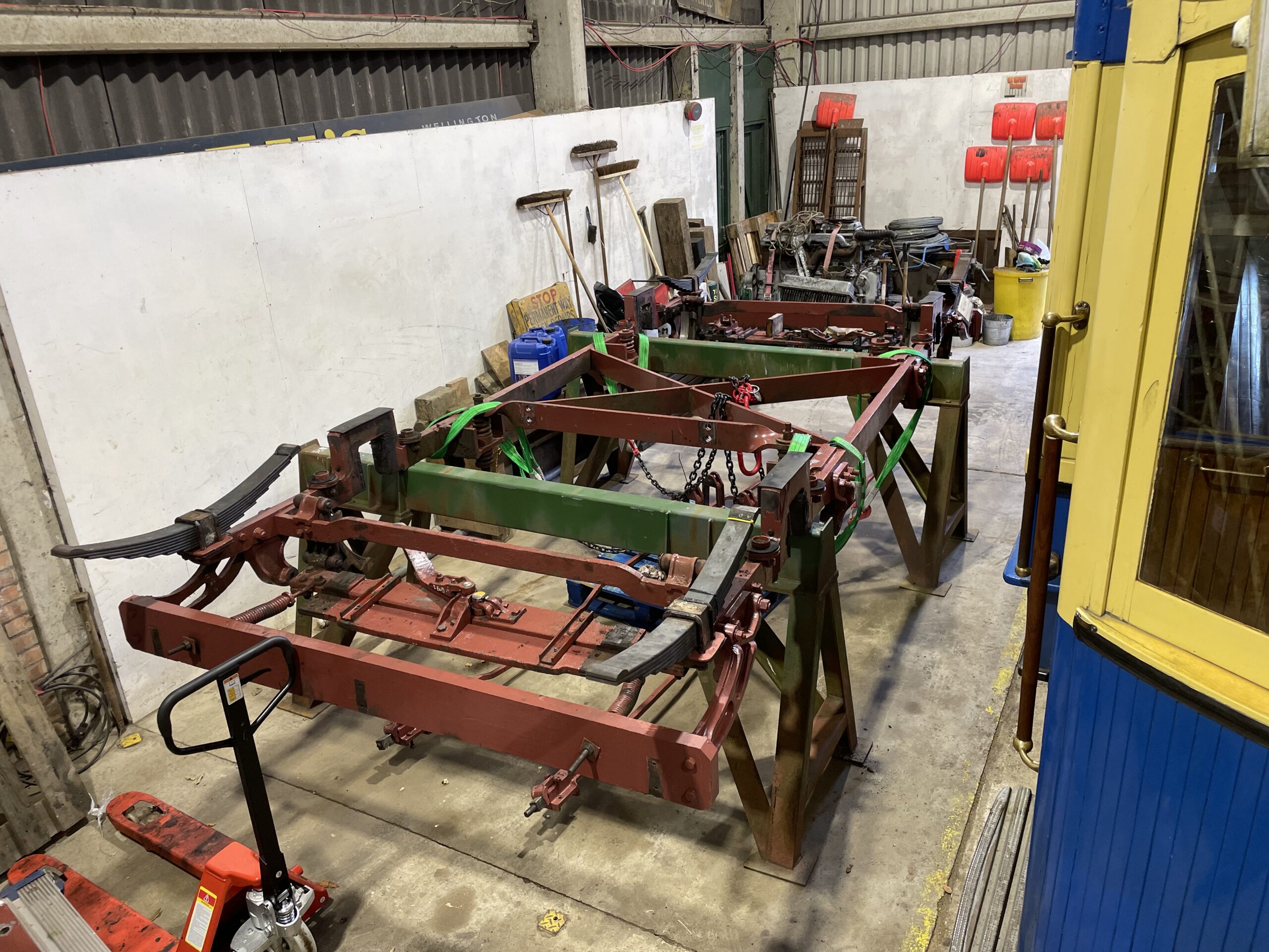
Below: The truck frame is now positioned on the trestles for painting and removal of the brake components for overhaul – principally removing and replacing bushes/pins where required.
Oporto 196
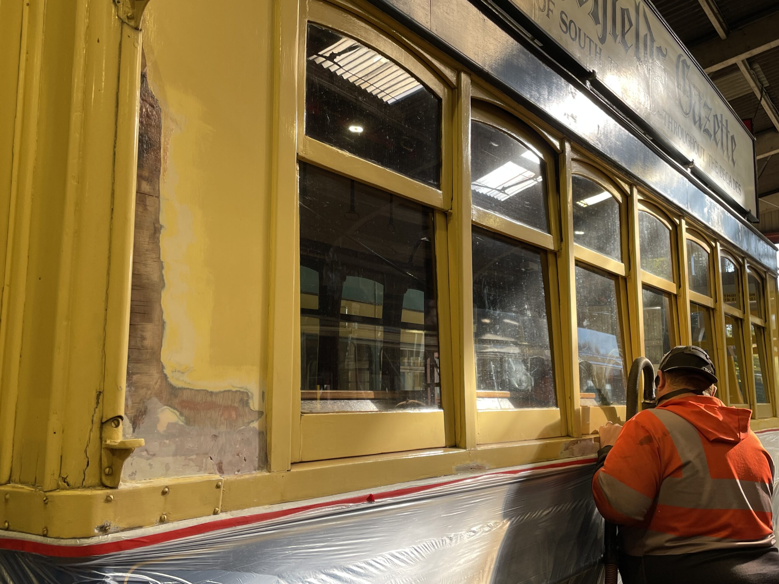
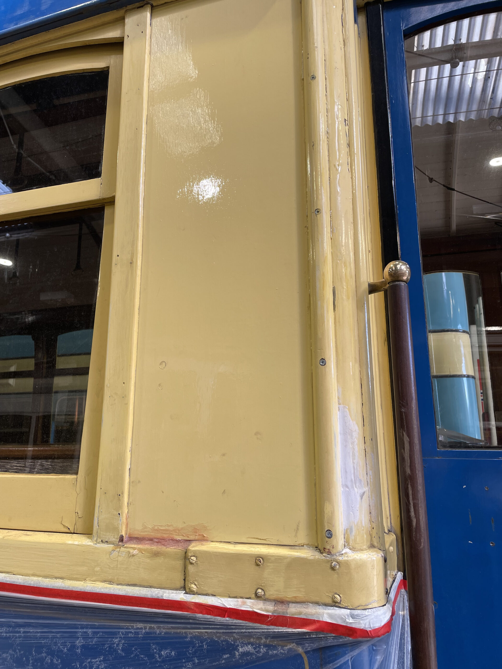
Below: On the 22nd October a concerted effort by John and Tony saw one of the panels on 196 replaced, several areas of rot treated and filled before the yellow shade (Primrose) of paint was reapplied to the affected areas. The tram then went back into service on the 23rd October. A further session of repairs is anticipated like this, aimed at smartening up its appearance and trying to prevent further water ingress to the body pending what will be a comprehensive overhaul at some point in the future.
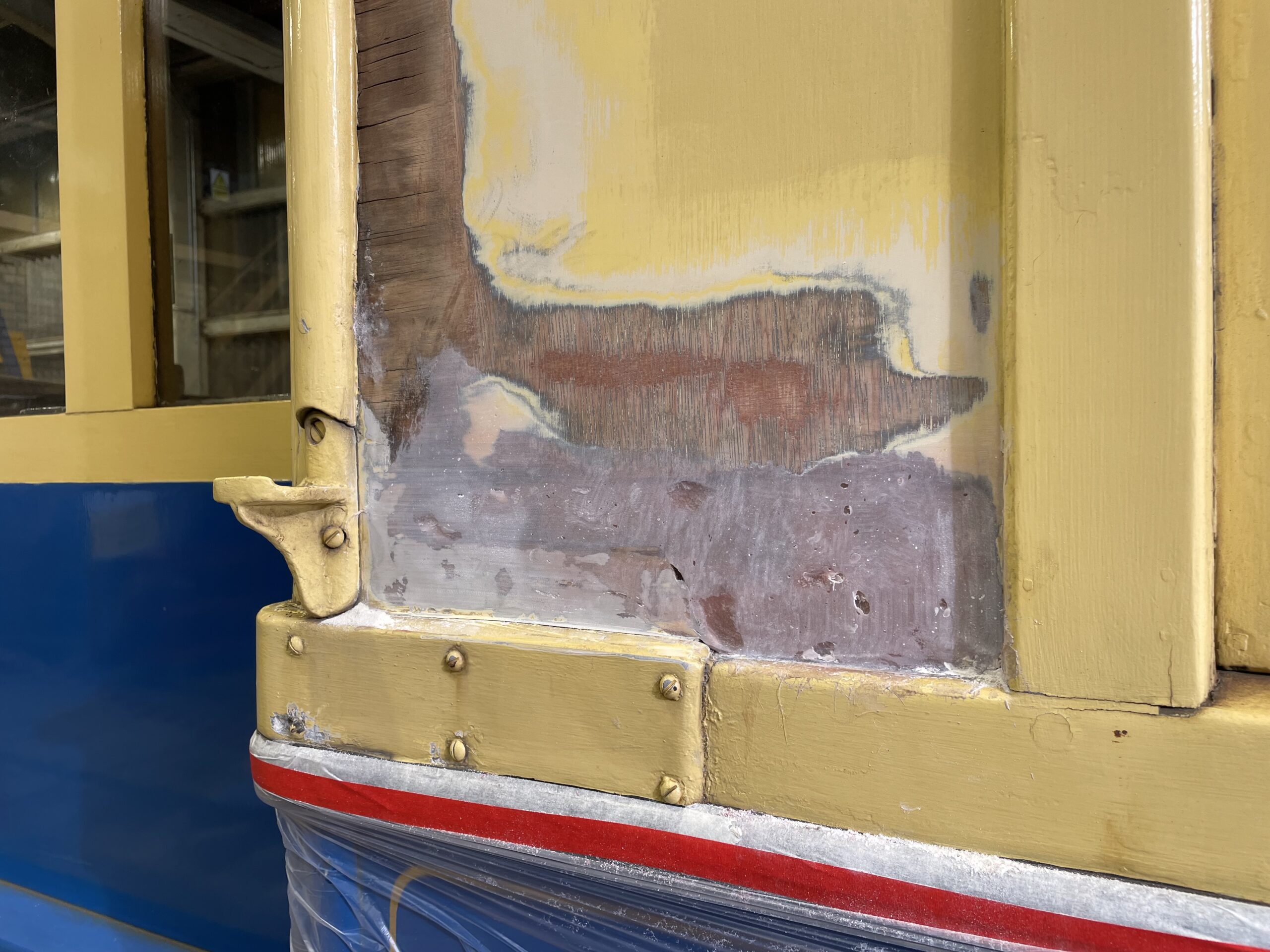
Below: One of the new panels after being fitted but before holes were filled on the beading screws and an application of Primrose.
Castle Eden Engine
Below: This project has become a rather pleasant distraction! Which probably explains why I keep giving it plenty of space on the blog! It’s very satisfying to see it being assembled for the first time since 1970? It’s another museum artefact coming in from the cold after 56 years (not dissimilar to the Darlington Corporation Bus Shelter project). It is also provoking some thought, technical conversation in the workshop and research that is all very refreshing for both the curatorial mind (that’s me!) and the engineers (Phil and Phill). I’m hoping that others reading this might also be able to chip in with observations/elements of the Castle Eden engine’s history too…
Phil has been busy assembling the engine, overhauling components or making new ones, as required. Meanwhile, the detailed file that is being created for the project (that will sit in our central collections database) has gathered together what we know (and don’t know!) about its history. As was referred to in previous posts, the engine came to Beamish in 1970 and was, it is understood, previously displayed in the Castle Eden Brewery reception area. I would love to see a photograph of it during this period of its life! I’ll save other information for a future post, but one of the key lines of enquiry that I’m pursuing is who the possible manufacturers were, and when it might have been built (a build date of 1830 is noted on the collection card, but it would be nice to substantiate this).
It is possible that the engine, if as old as suggested, originated at the Castle Eden Foundry – which, under Thomas Richardson, was active between 1830 and 1838 (building engines from 1835 to 1838) when it relocated to the Middleton Ironworks in Hartlepool. This would give a window of 1835 – 1838 for the manufacture of this engine – if it is indeed a product of Thomas Richardson and the Castle Eden Foundry. We do have have a Castle Eden Foundry exhibit in the collection, dating from 1848 – this being the water tank that is situated alongside the Colliery Winding Engine in the Colliery. This is a section of a larger tank, collected from Belford Station (where it was the tank for the North Eastern Railway Water Tower) in 1973.
So, what’s been happening with the engine in the second half of October? Phil has whitemetalled the main crankshaft bearings – as seen here. The same process as was applied to the Leyland Cub engine overhaul was used and the bearings were then machined to match the crankshaft journals.
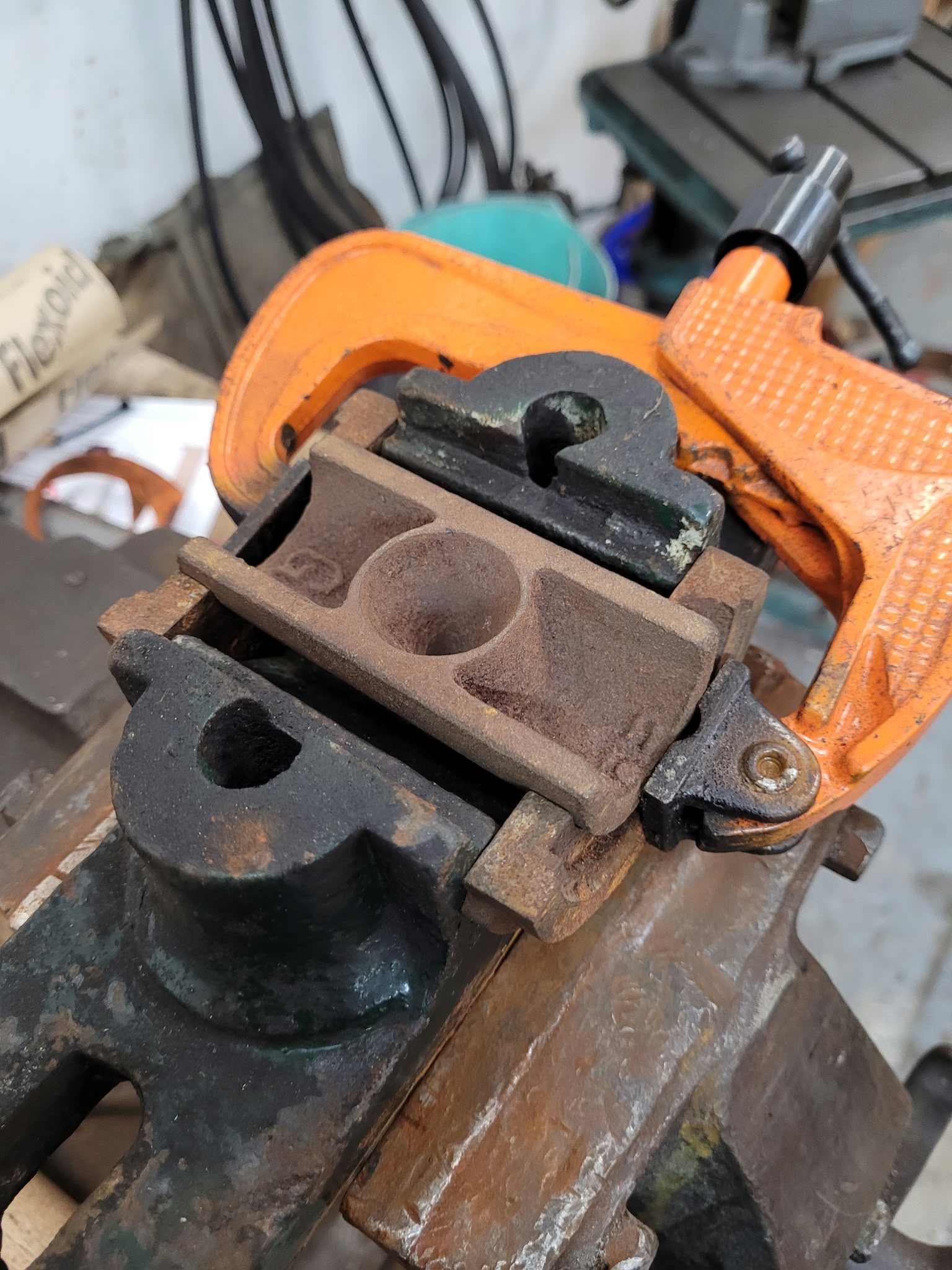
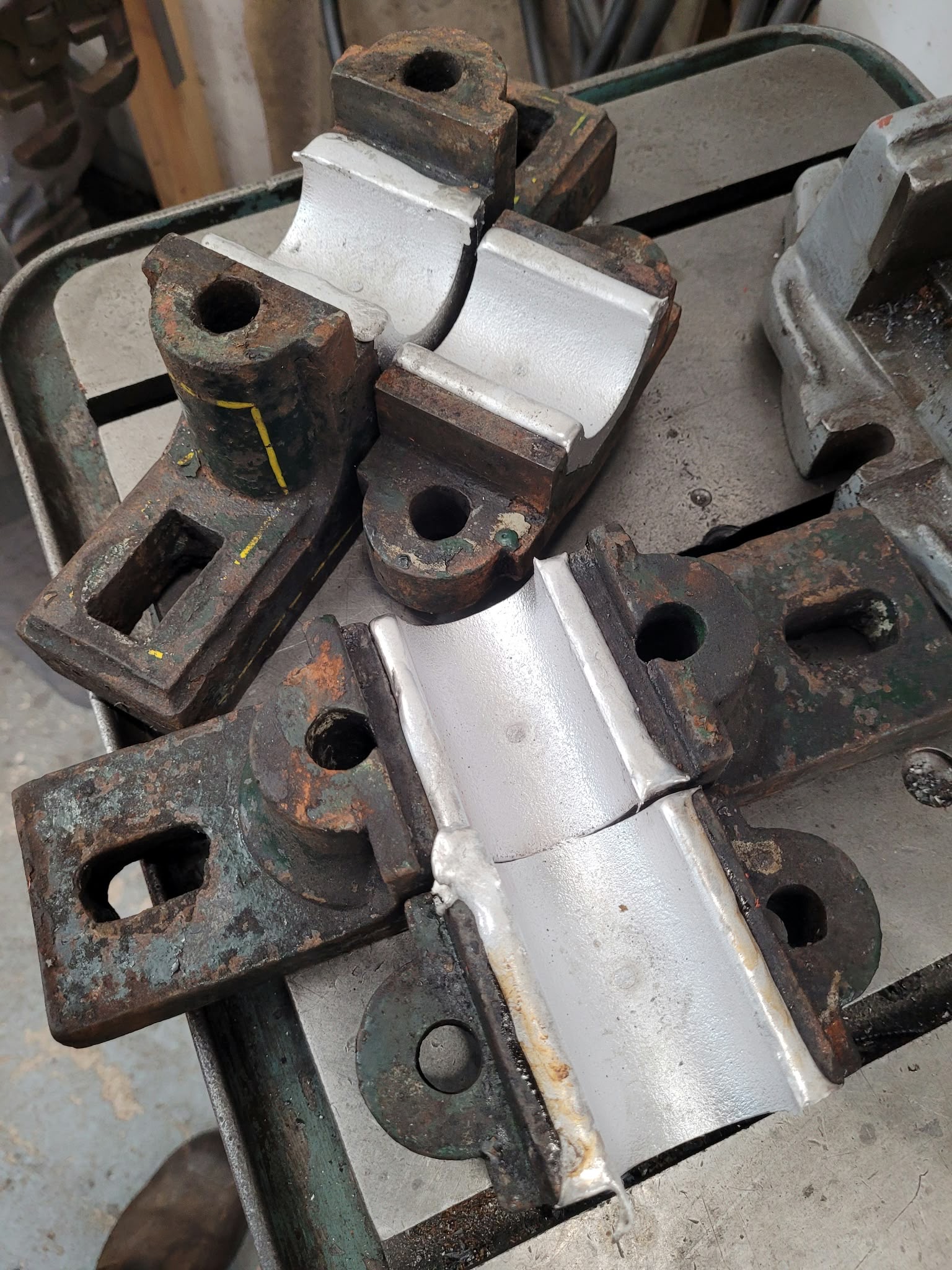
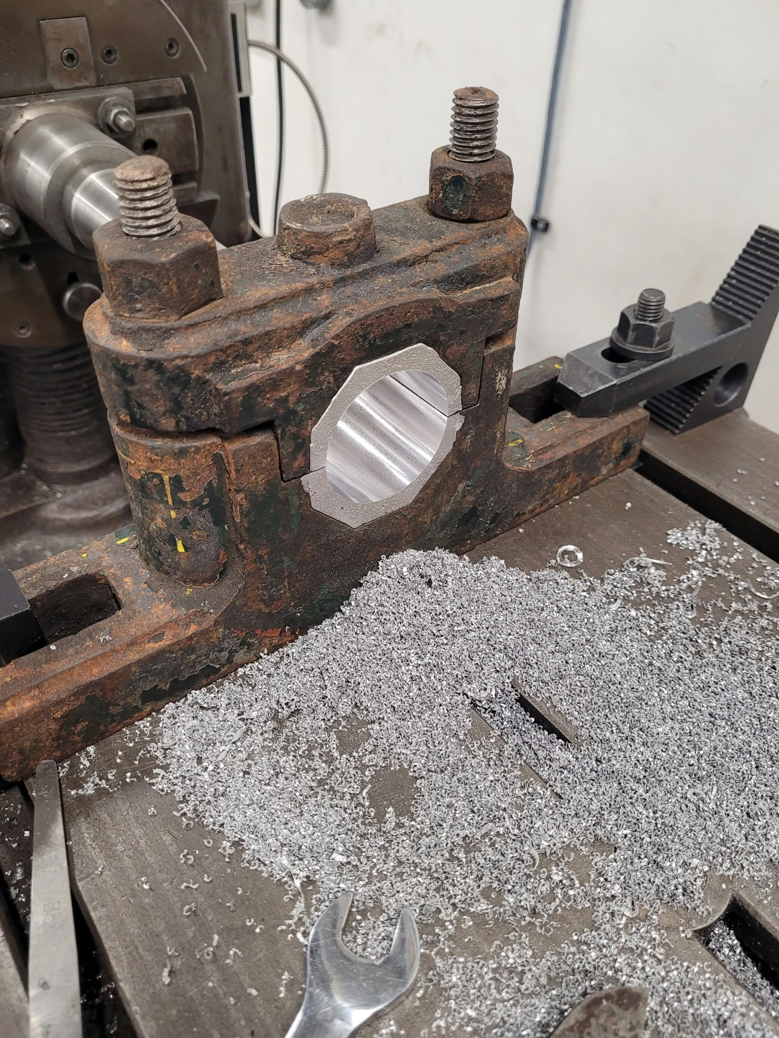
Below: The bearings, paired together ready for boring out to fit the crankshaft journals. Usefully, with the pedestals not attached to the engine bed, they can be used to clamp the assembly on the horizontal borer for this work. Shim was used to pack them apart slightly, to allow for adjustment upon final assembly.
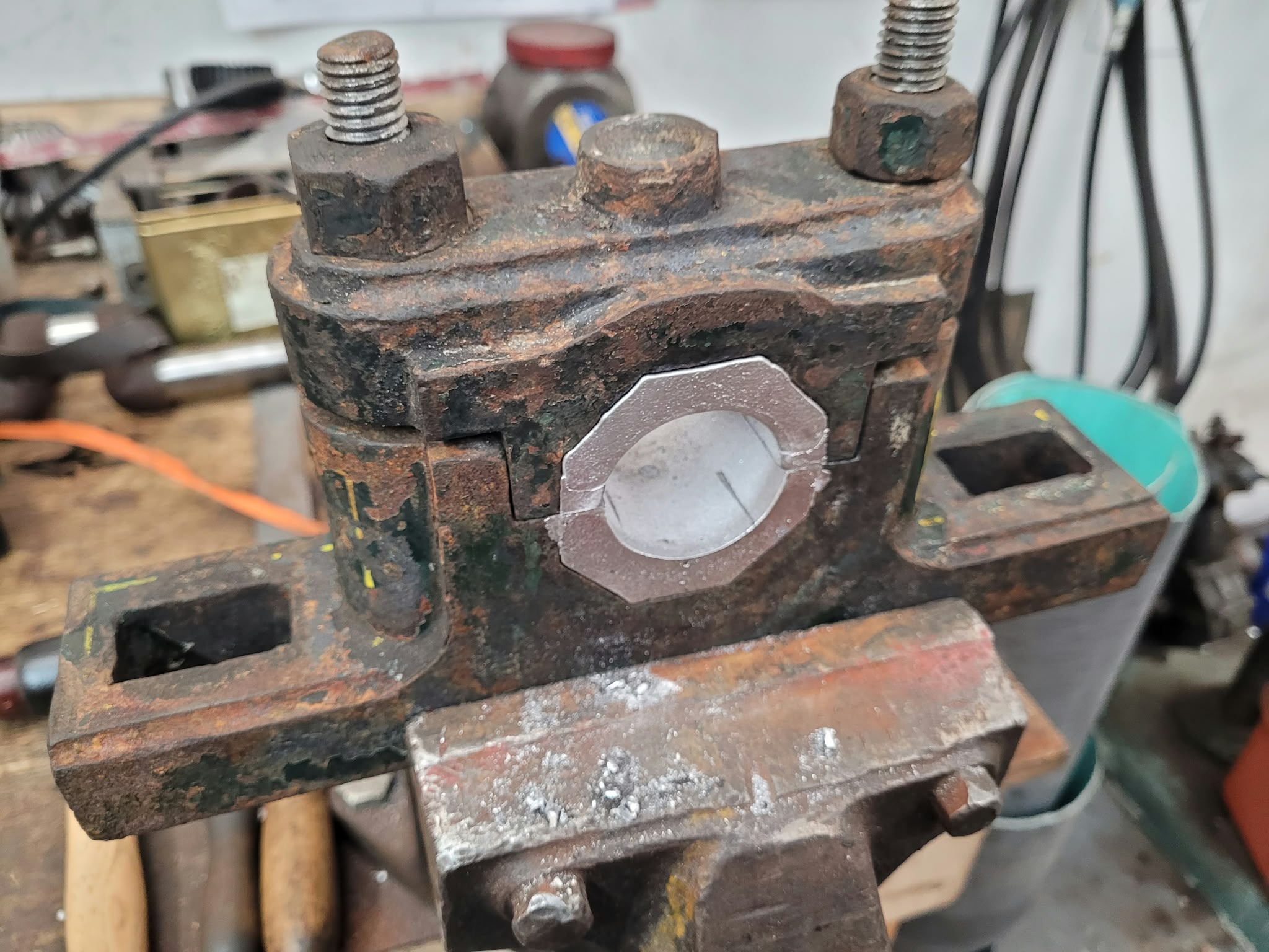
Below: The shiny internal surface indicates where the borer has done its work – the shavings/swarf can be re-cycled as whitemetal is not cheap!
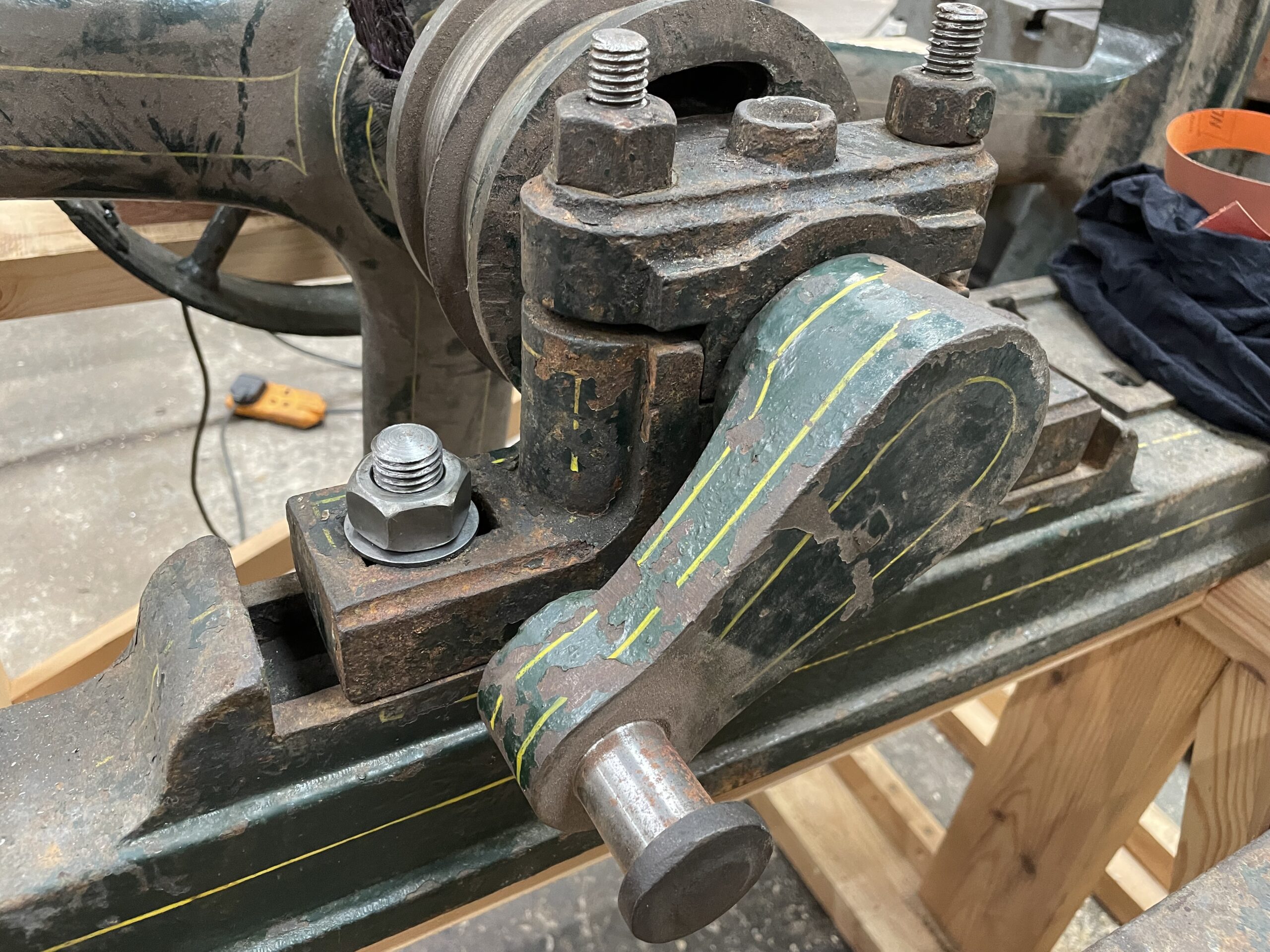
Below: The whitemetal isn’t visible in this view, but is part of the bearing cap and crankshaft pedestal – seen here after assembly with the crankshaft in situ. Note the new hold-down bolt and nut – the corresponding bolt for the other end of the pedestal was re-usable, but has been fitted with a new nut. Also of note is the dish at the top of the pedestal, for lubricating oil. This does not have an internal thread, so presumably the oil was either dripped in from a separate vessel, or was minimally applied (but regularly) by the engine operator.
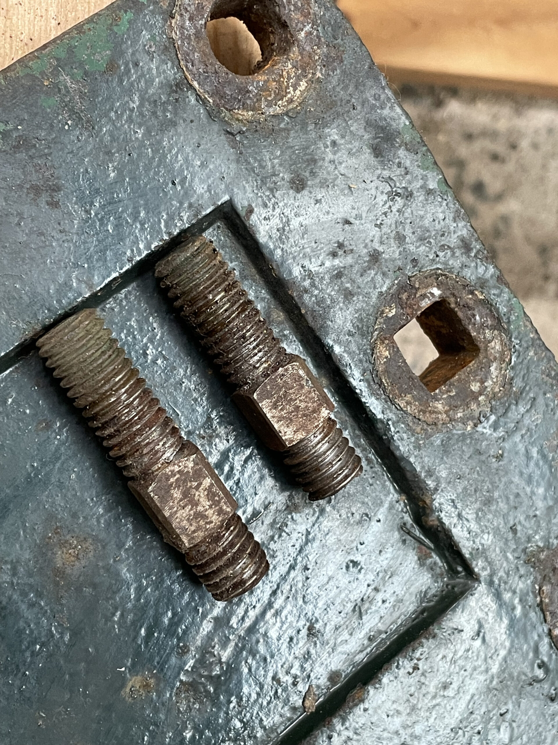
Below: Another notable feature os the way in which the valve chest cover is secured. Rather than locating onto studs, inserted into the valve chest casting, this engine utilises headless bolts that pass through both components, with a nut at each end to clamp the components together. The holes in the cover are square, and locate the corresponding section of the bolt (also square) to prevent it rotating. With one length of thread being longer than the other, this allows for the tighter clearance against the cylinder casting (where it may be impractical to thread a conventional bolt through the holes).
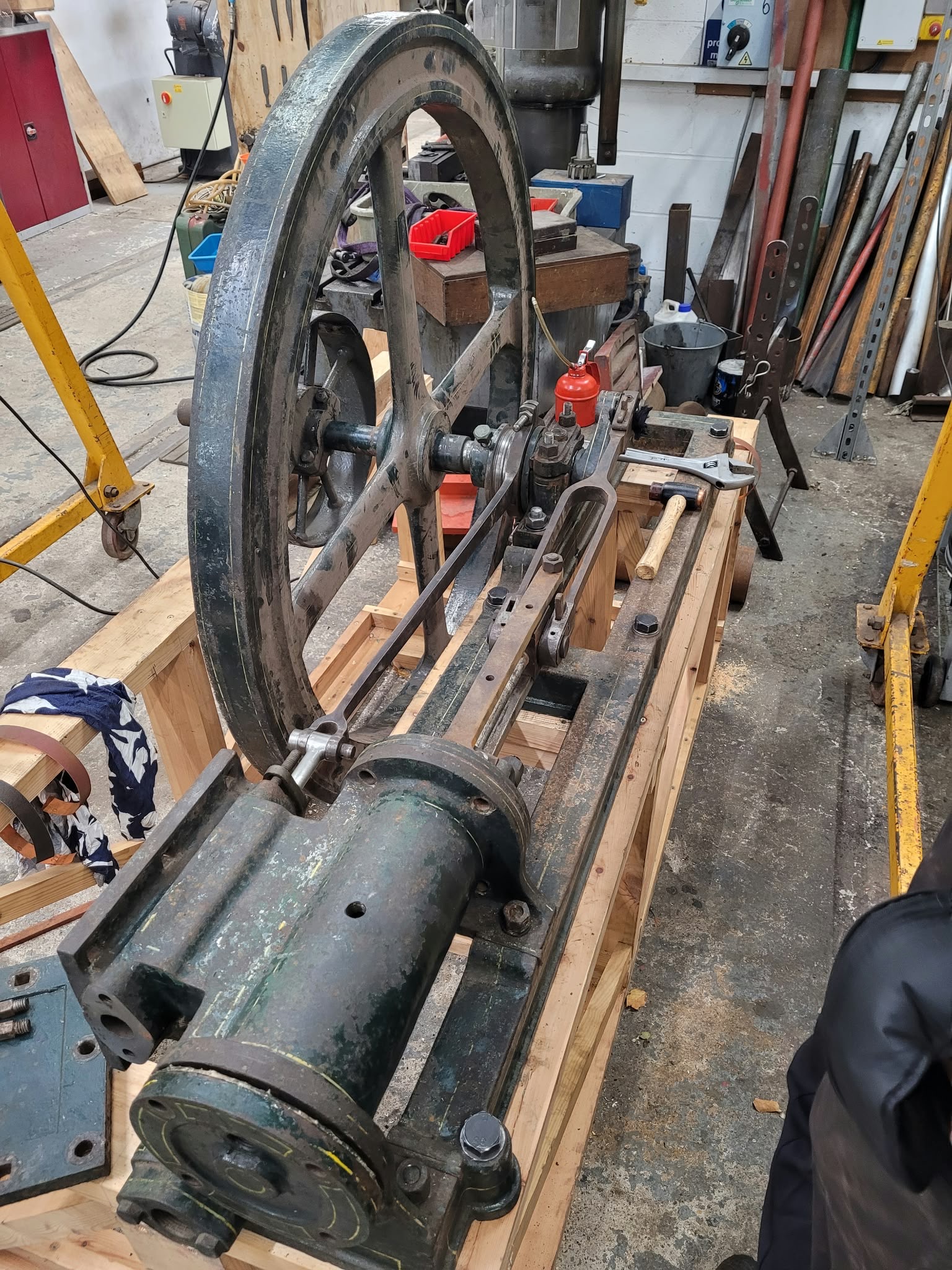
Below: With both bearing pedestals ready to accommodate the crankshaft, the first trial assembly is underway in this view – the connecting and eccentric rods have also been fitted. The little end still requires new brasses manufacturing but at this stage, this was the most complete the engine had been something like five decades or more, I would guess.
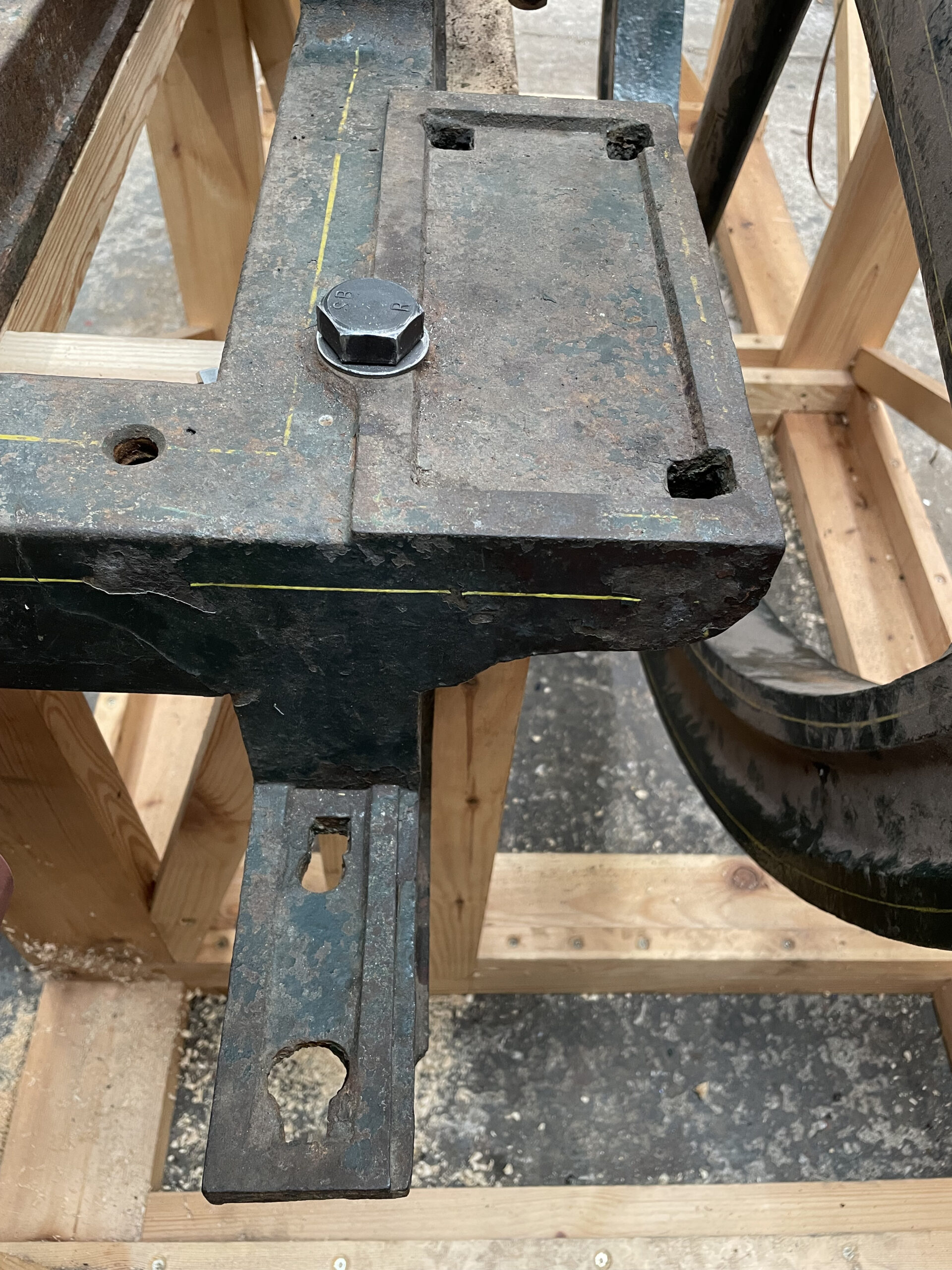
Below: An intriguing feature of the engine is this baseplate and bracket. They align with an eccentric and were presumably associated with a water pump (boiler feed perhaps?). With no evidence of what was fitted, we won’t attempt to replicate anything – but if new information was ever to come our way, we could look at re-establishing this feature.
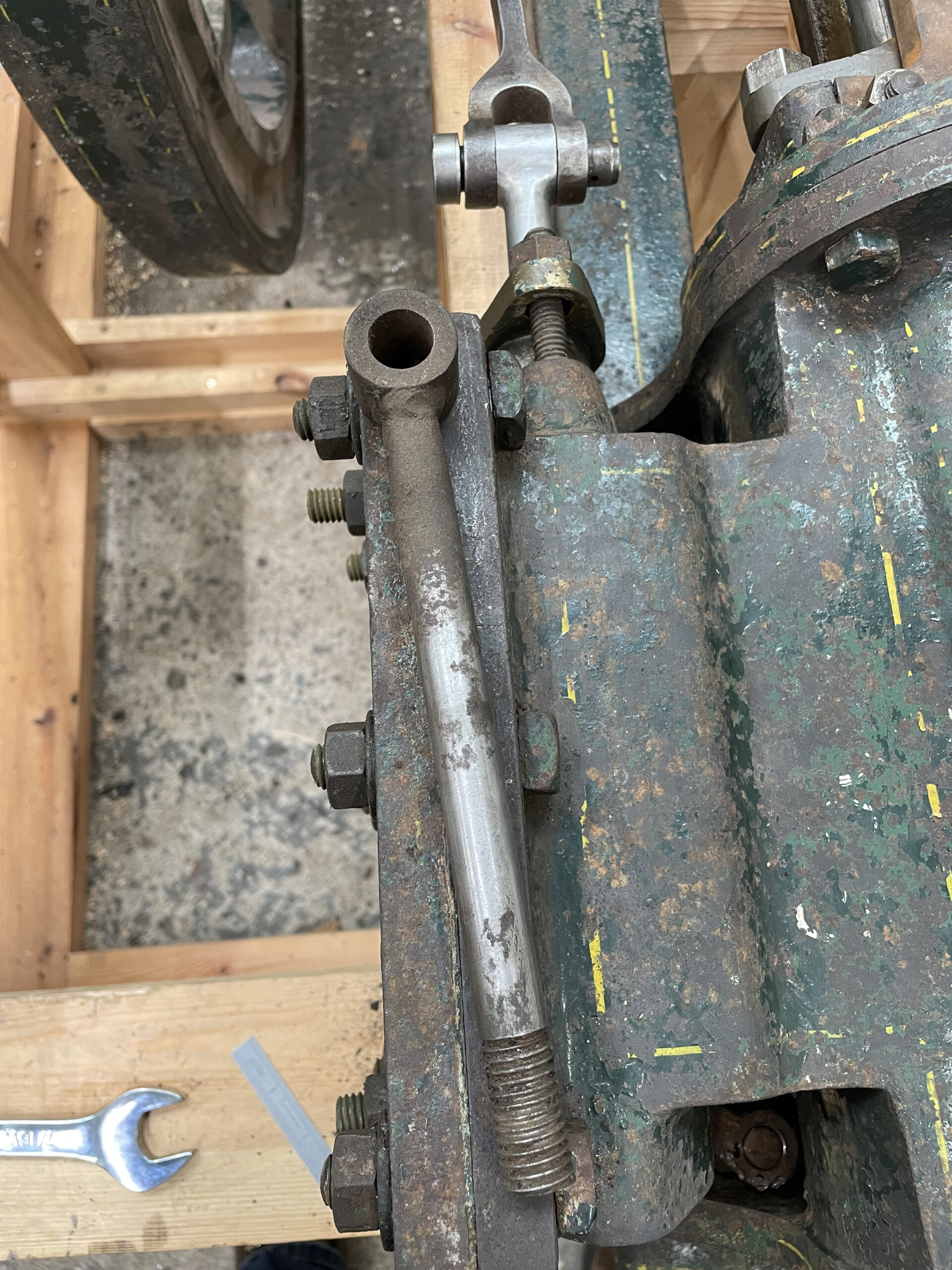
Below: The old and new valve rods – the old one is sat on top of the valve chest – clearly of later manufacture than the engine (on account of having the valve rod end welded to the rod). The new rod has been fitted to the engine and the brighter tone indicates its position within the valve gear of the engine in this photograph.
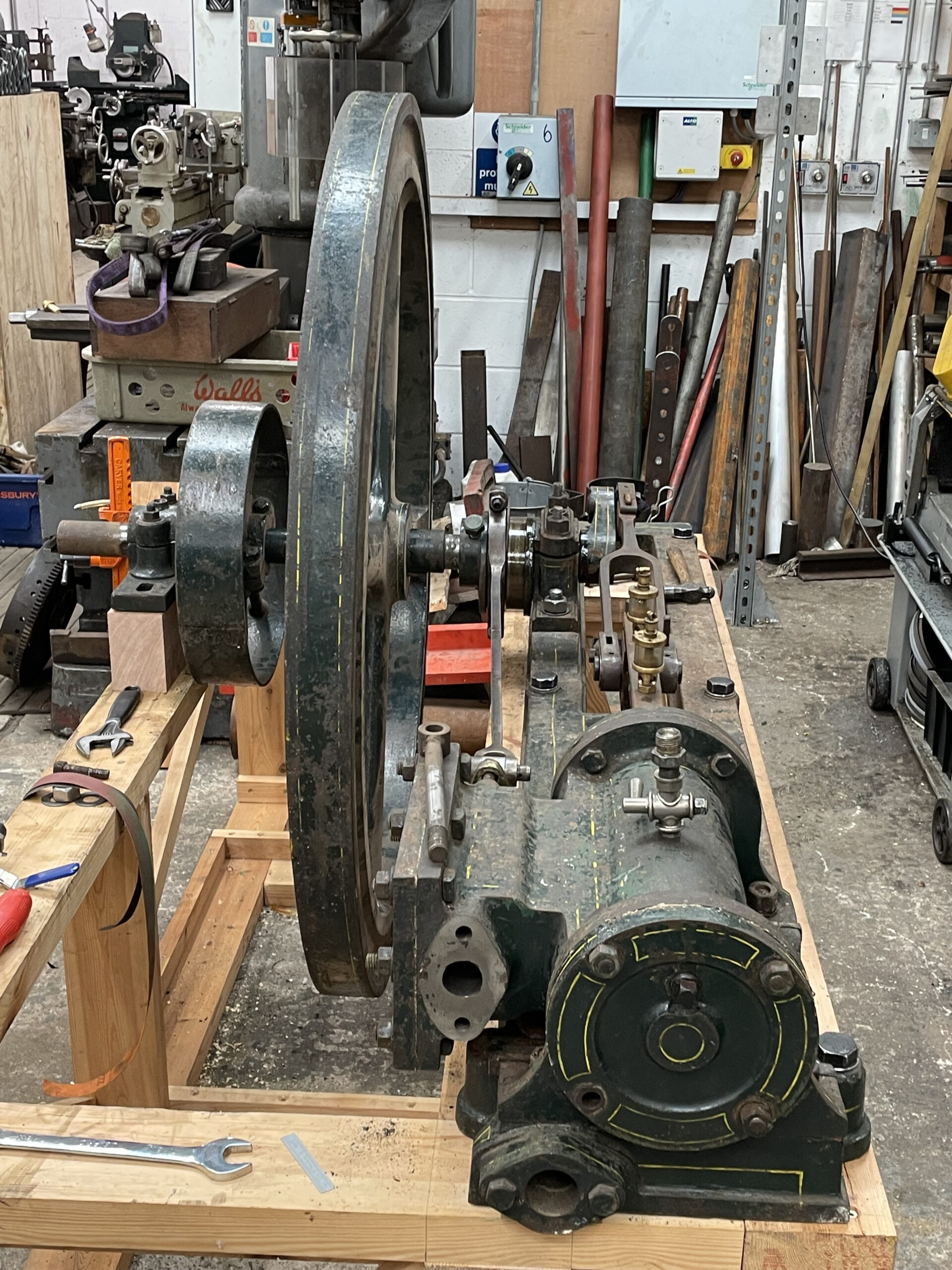
Below: With a crude big end brass fitted for the purpose of testing, the engine did manage to turn over on air. A new big end brass was subsequently manufactured.
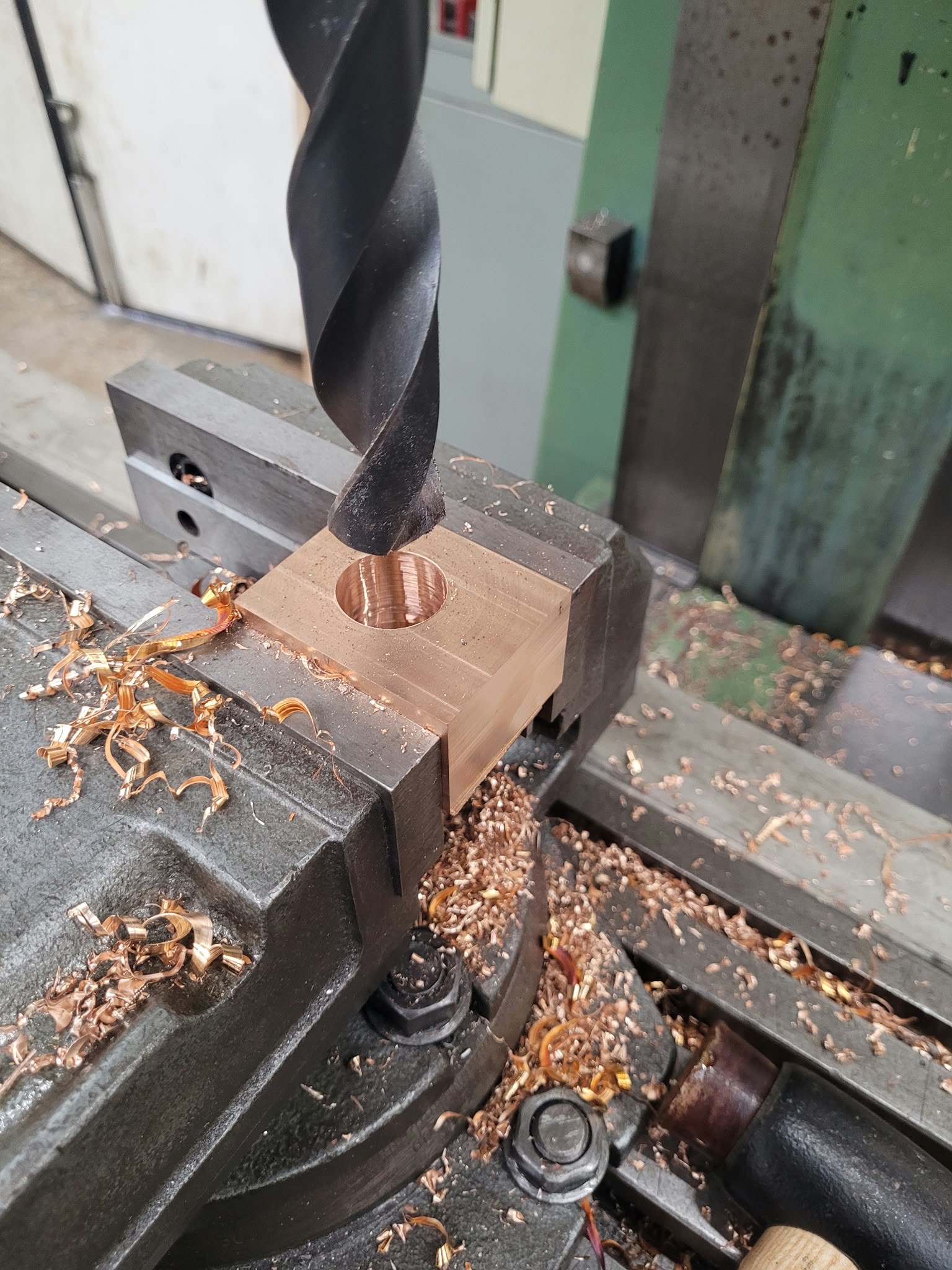
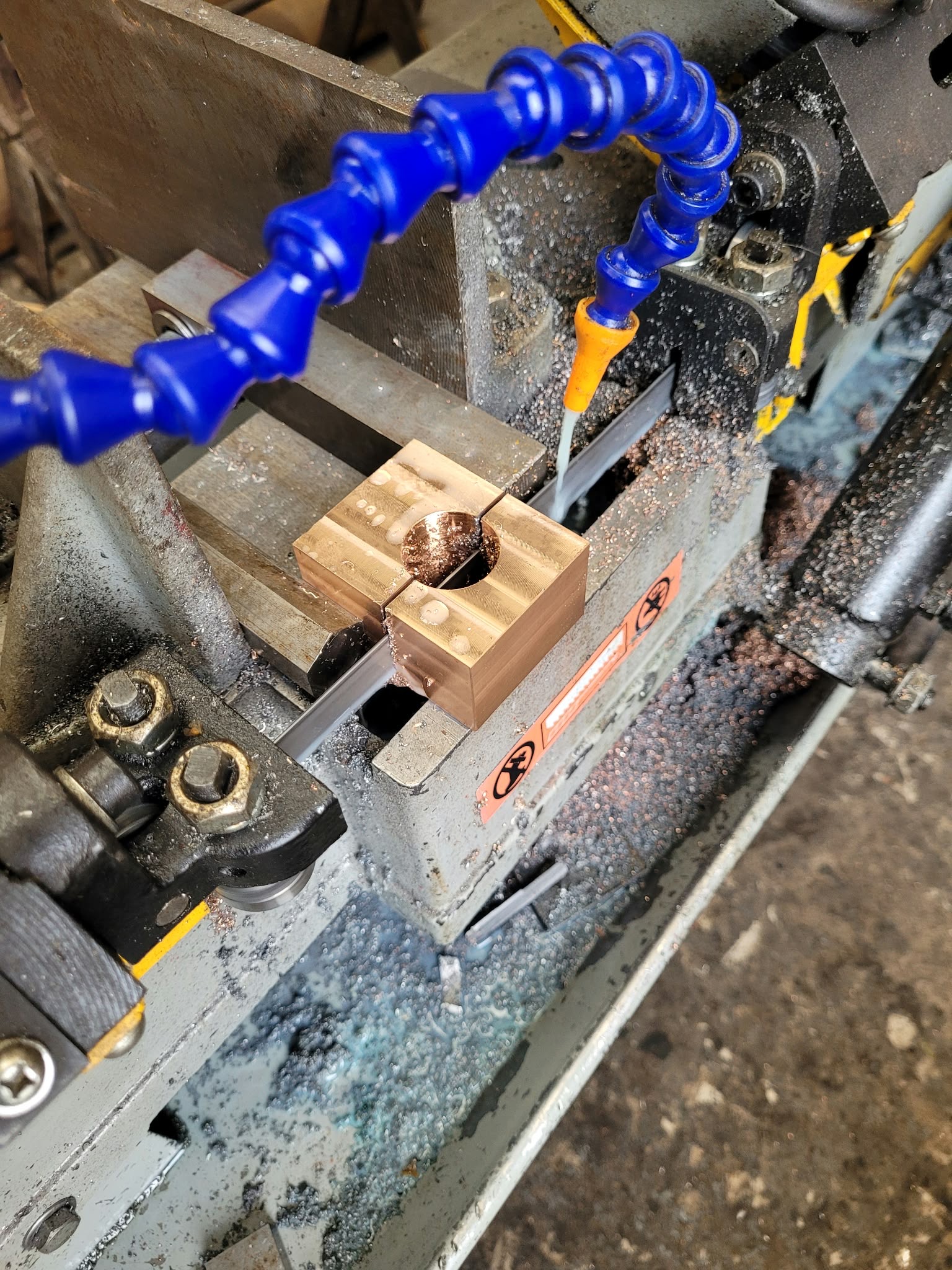
Below: Manufacturing a new big end brass – the first step was to drill/rough machine the block to size, complete with hole for the big end crankpin.
 #
Below: The brass was then cut into two pieces.
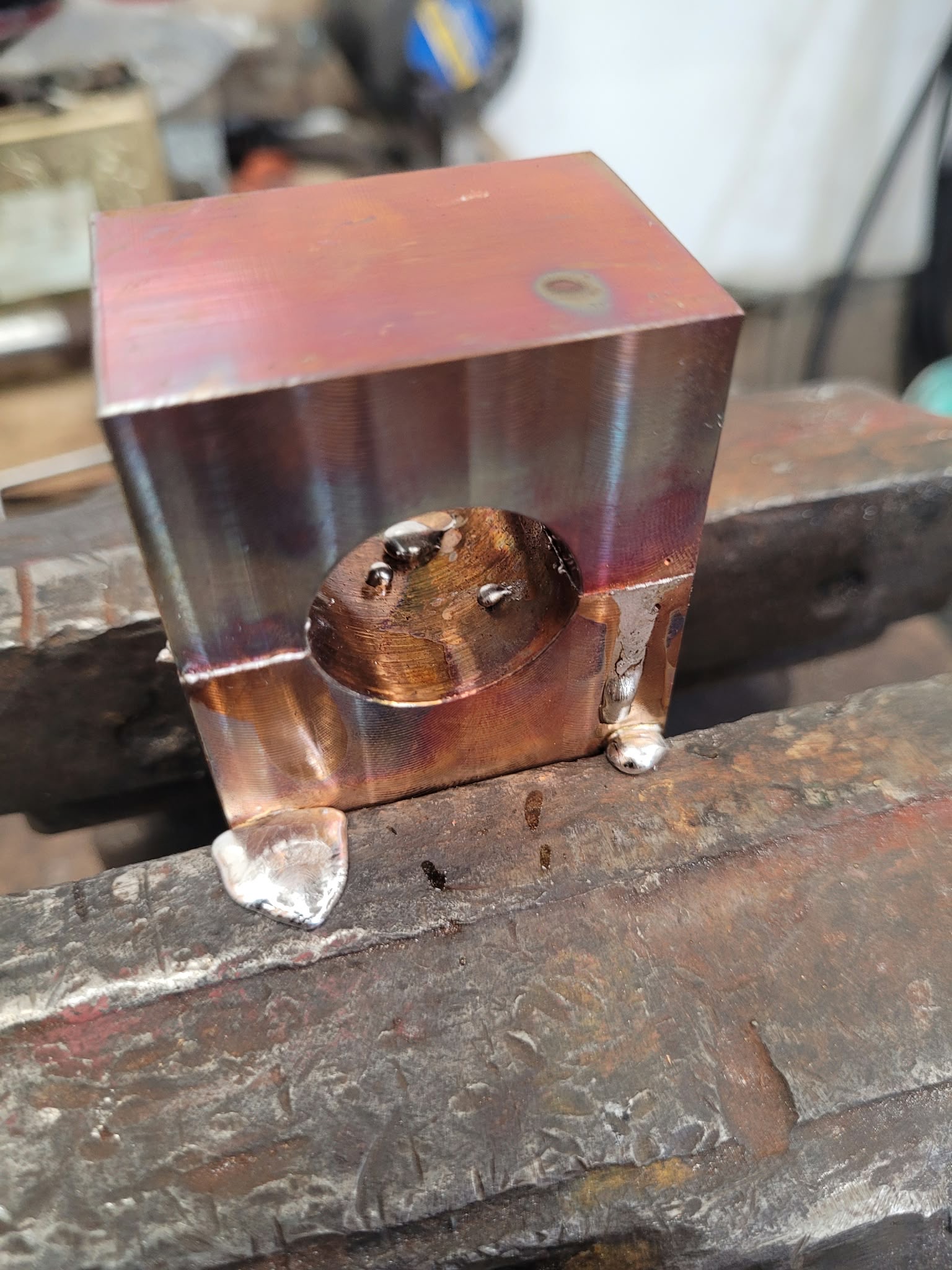
Below: After soldering back together, the block was ready for final machining – knowing the two parts could be separated later in the process.
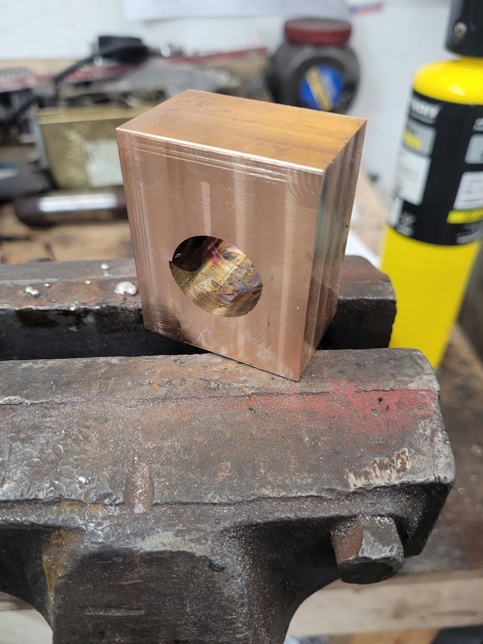
Below: The final outside dimensions – pending profiling the D shape.
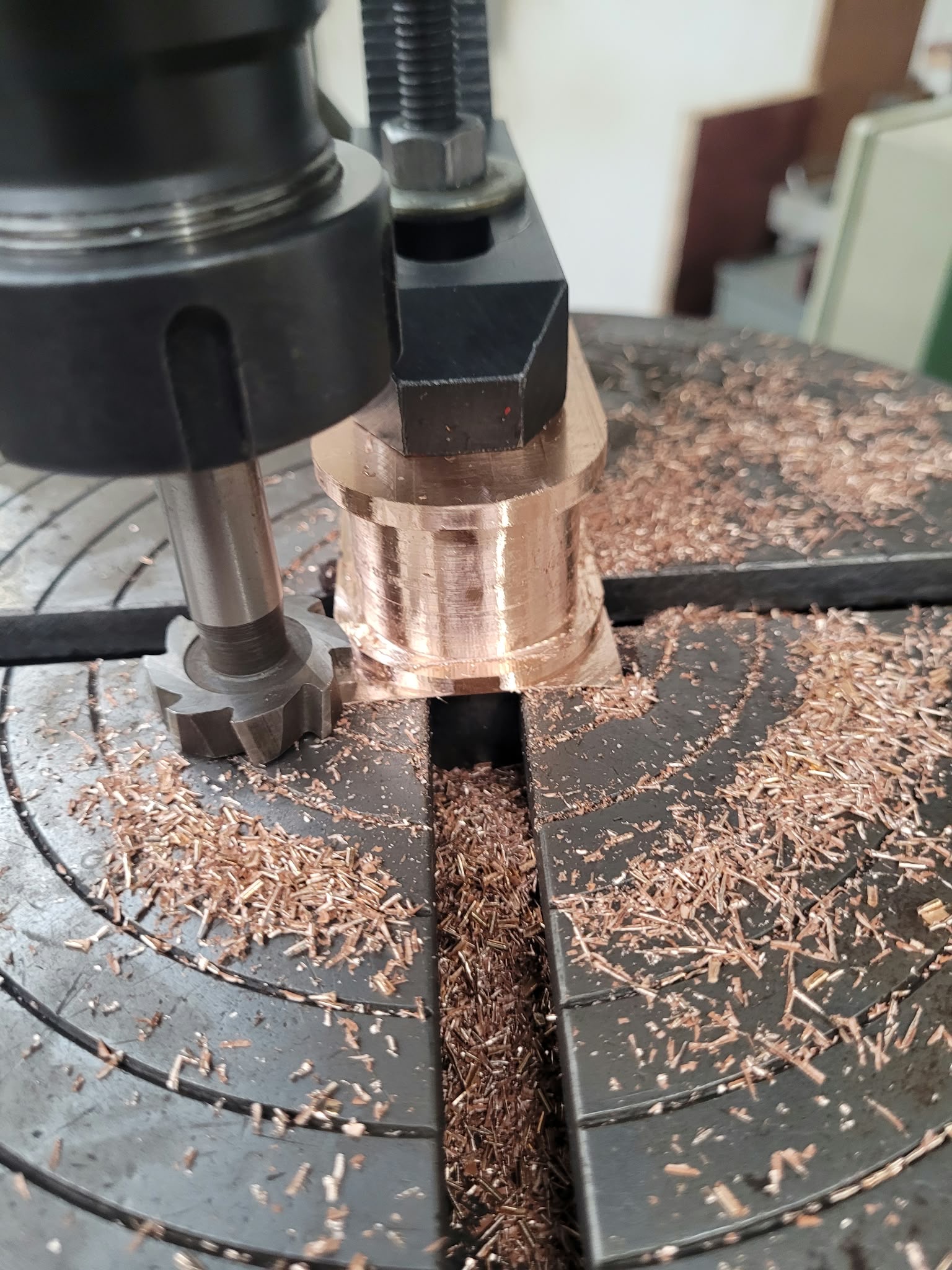
Below: Machining the radius onto the bearing brass using a rotating table on the milling machine. This process required a rebate to the same profile, in order to fit within the big end strap.
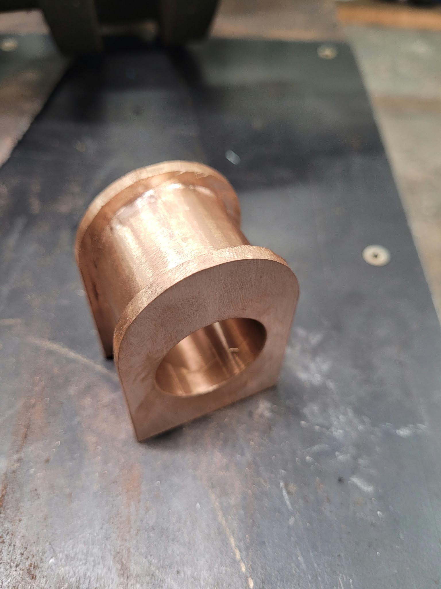
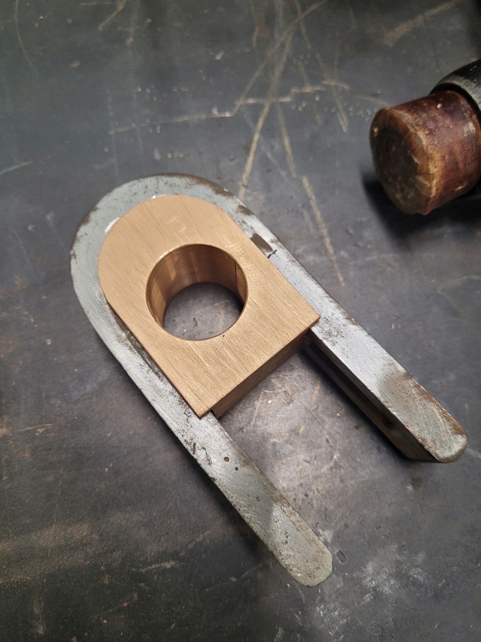
Below: The completed brass, before separating back into two pieces, sat within the big end strap to show the principle.
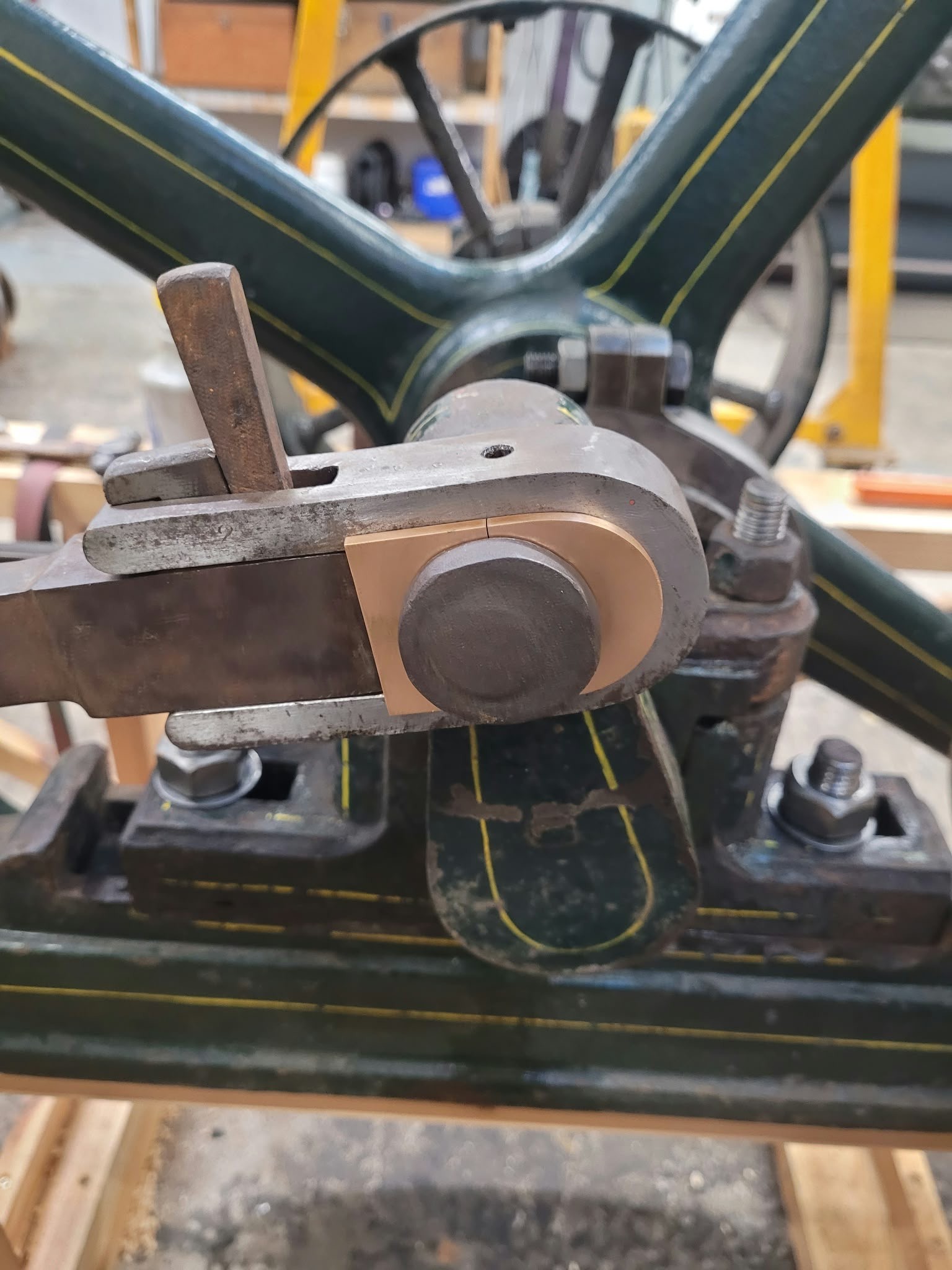
Below: The new big end brass assembled onto the connecting rod/crankshaft.
Crosville 716
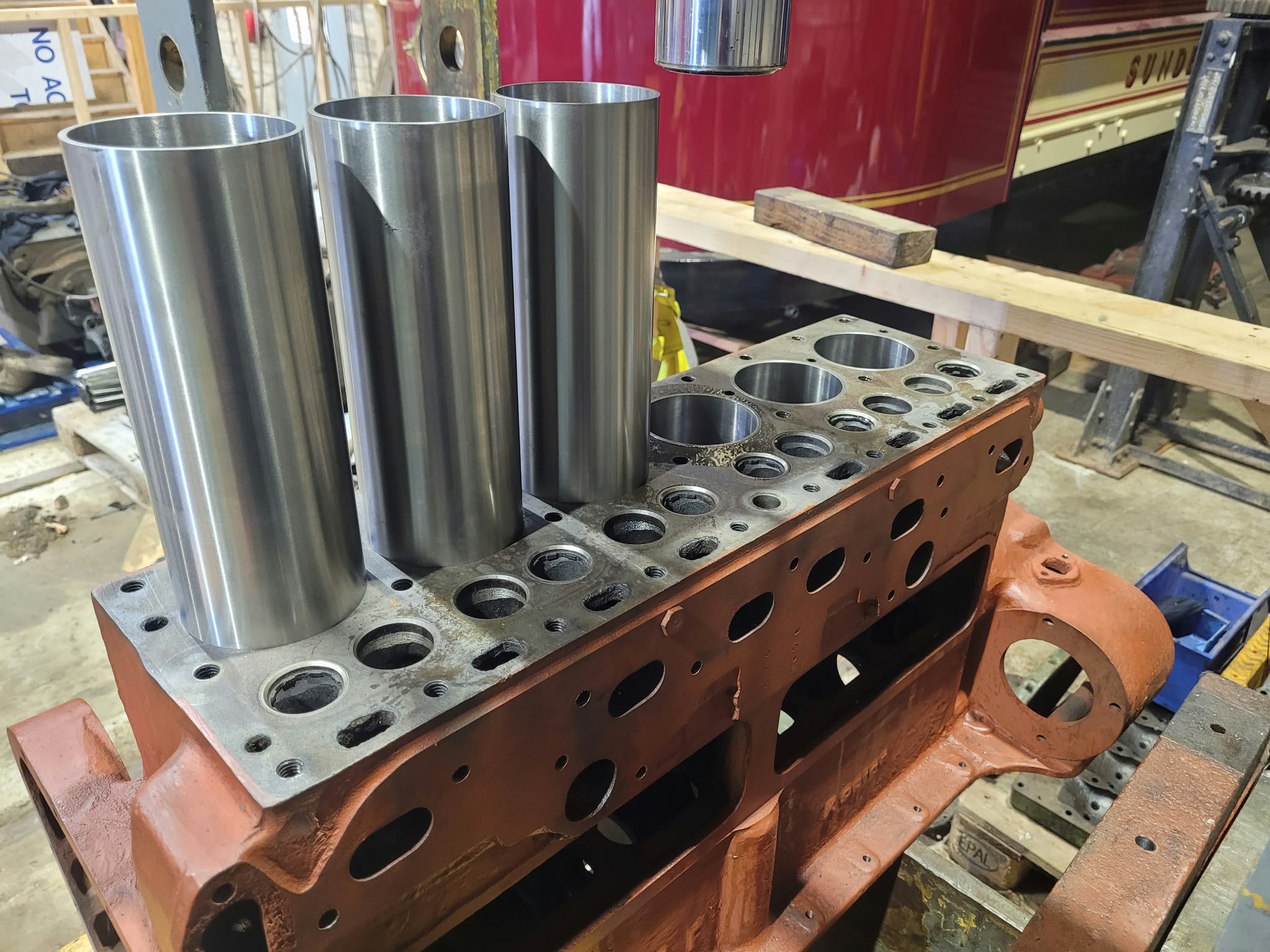
Below: The new cylinder liners arrived for the Cub’s engine overhaul in the middle of the month.
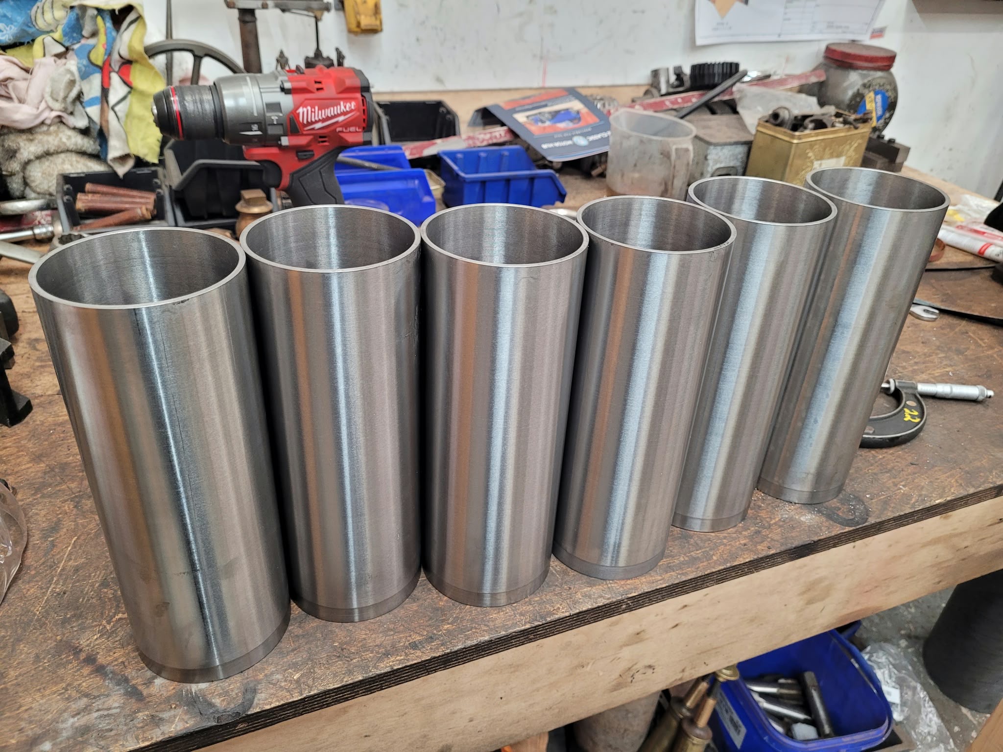
Below: These were pressed in at between 6 and 8 tons pressure.
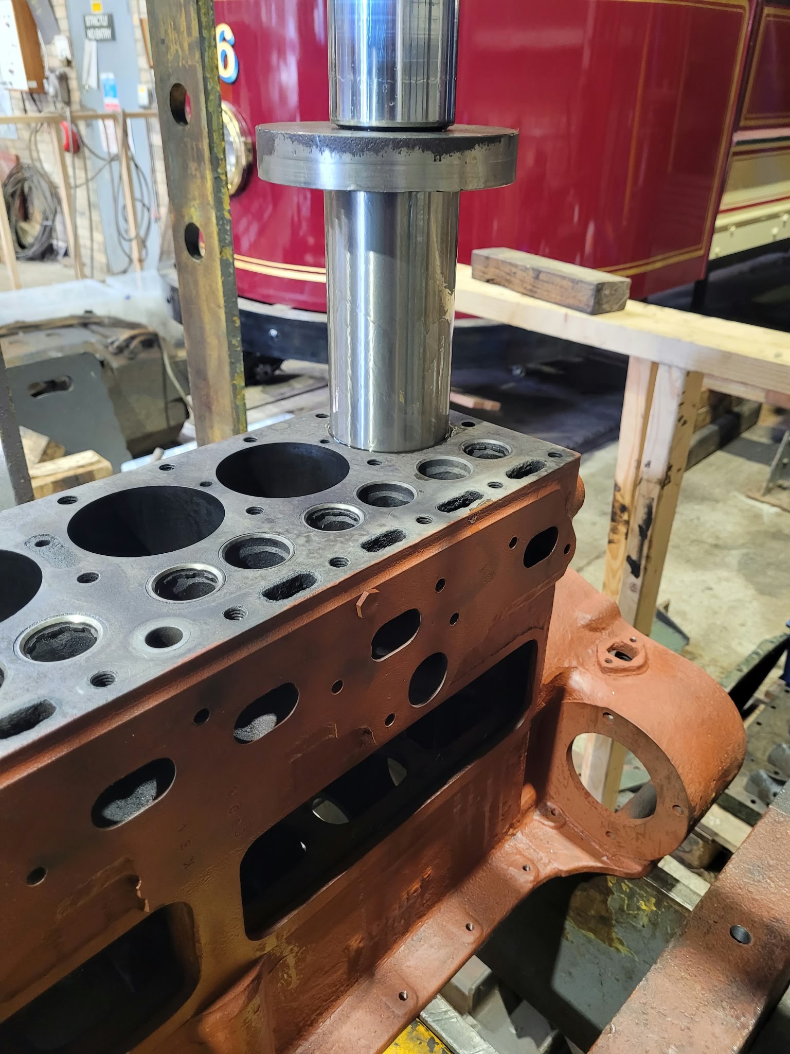
Below: Three in, three to go…
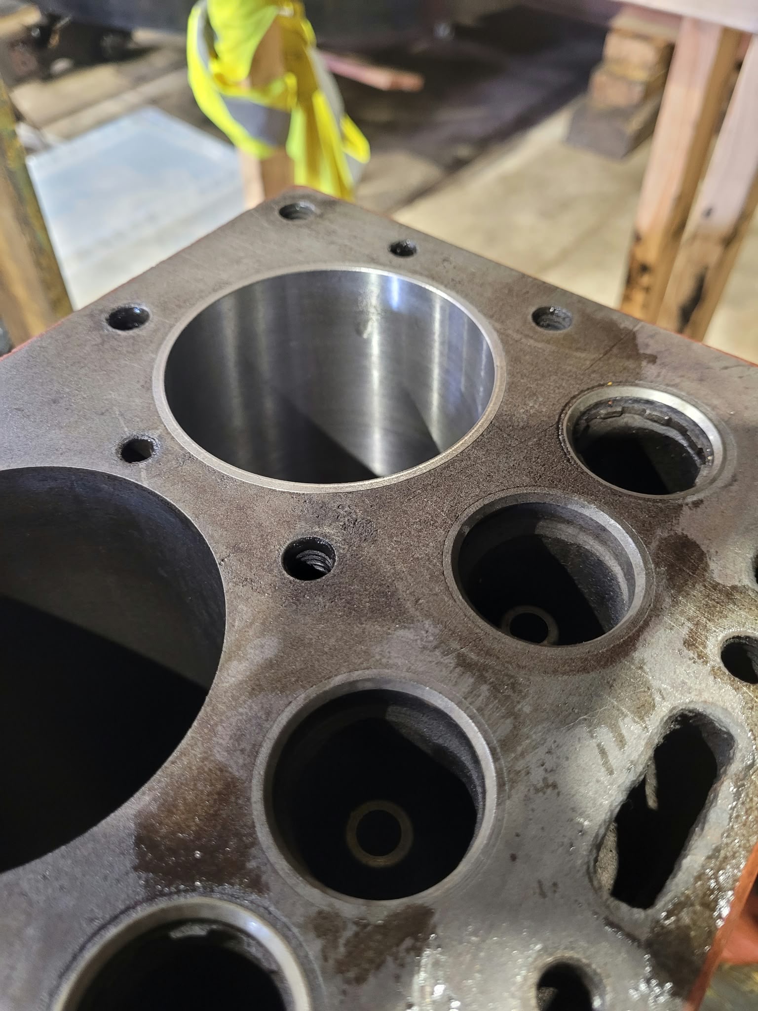
Below: A close up view of one of the liners in place, with the valve seats (inlet and exhaust) adjacent.
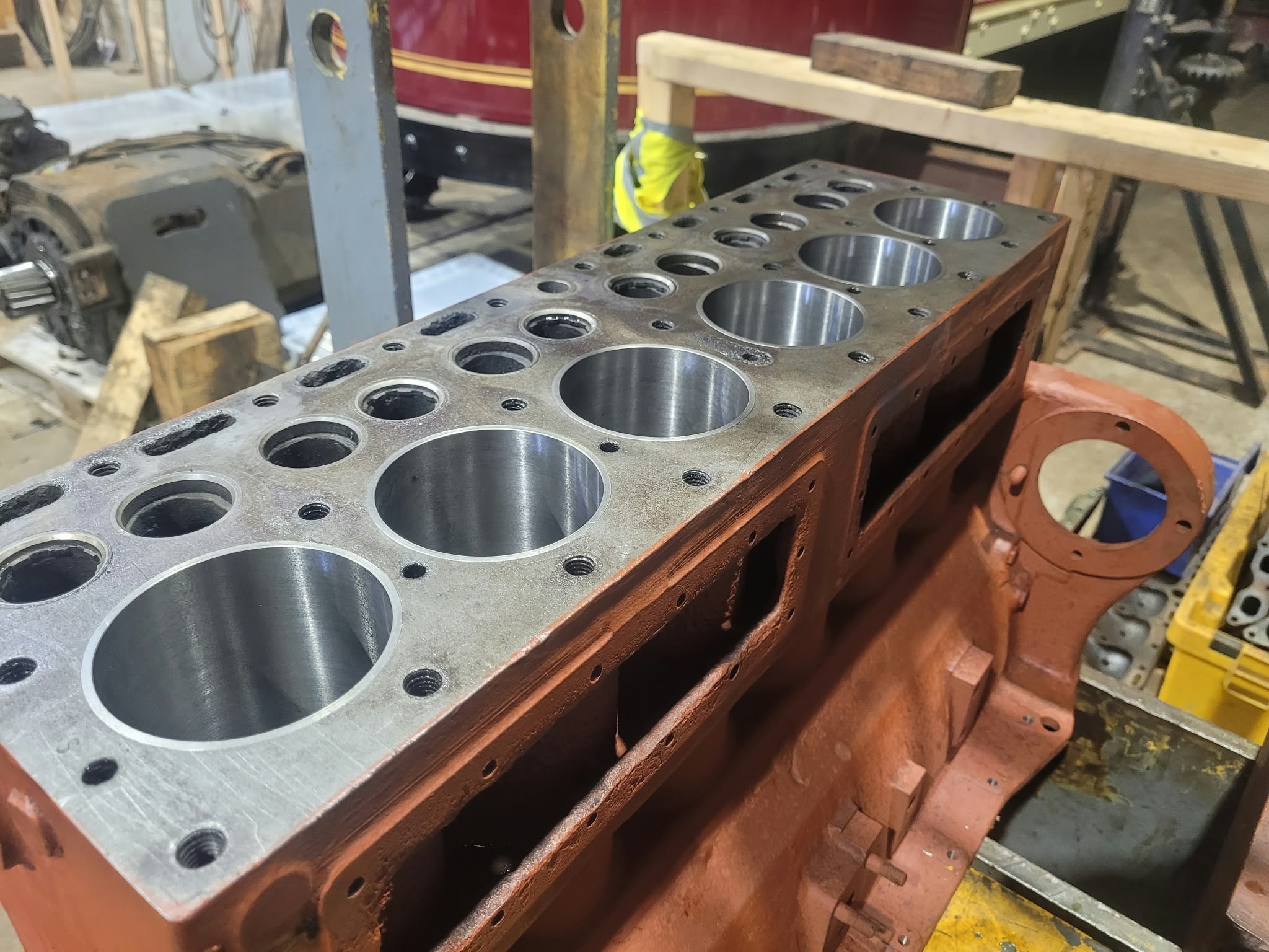
Below: With all of the liners in place, the block and head have been sent away for skimming, the valve seats witnessing, to tidy them up, and the unit pressure tested. After this, reassembly can begin.
Infrastructure
Below: The water hydrant box is now installed, next to the Darlington Corporation bus shelter. The benches and signs are still to add, but are not far away from completion now.
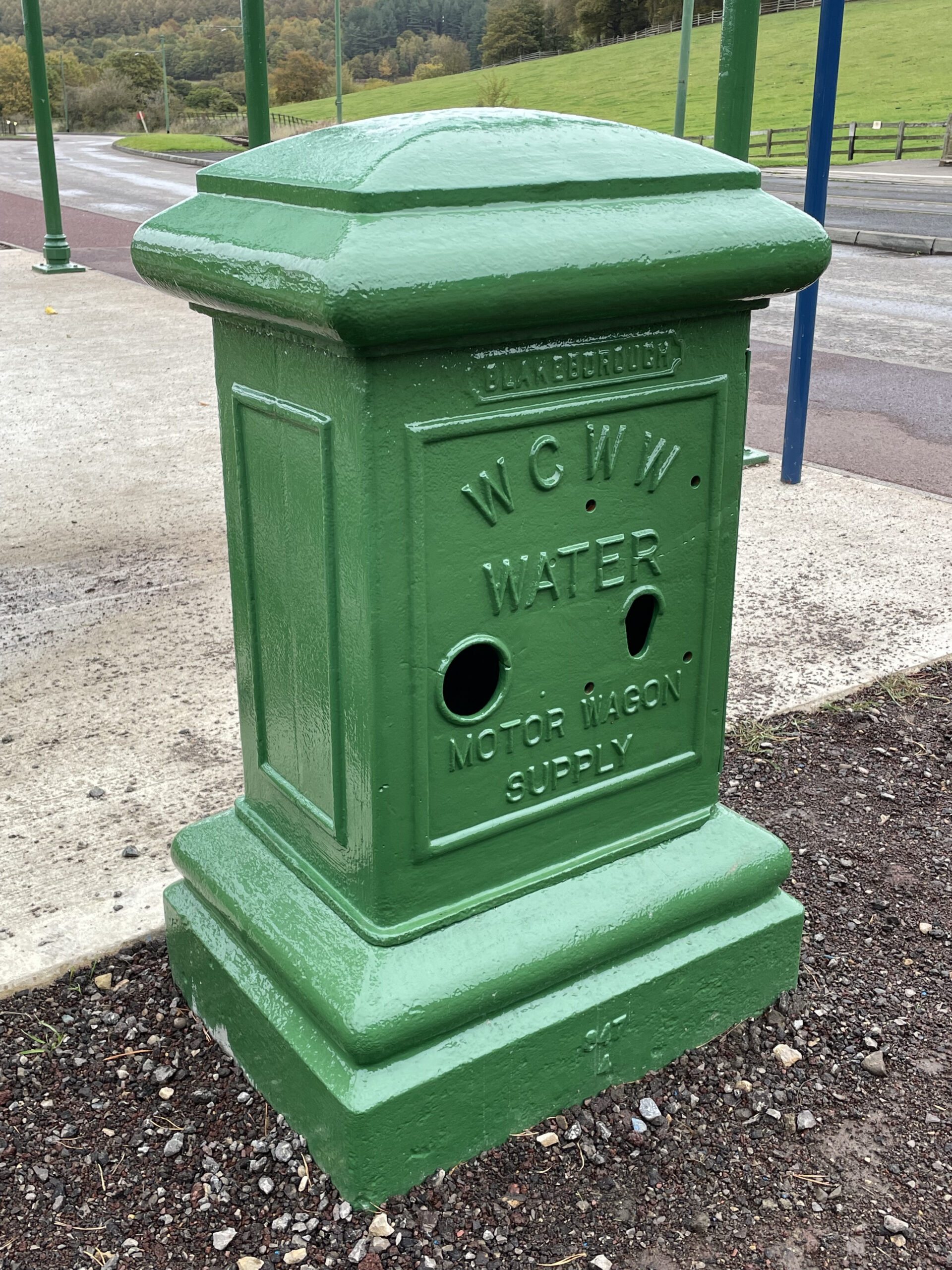
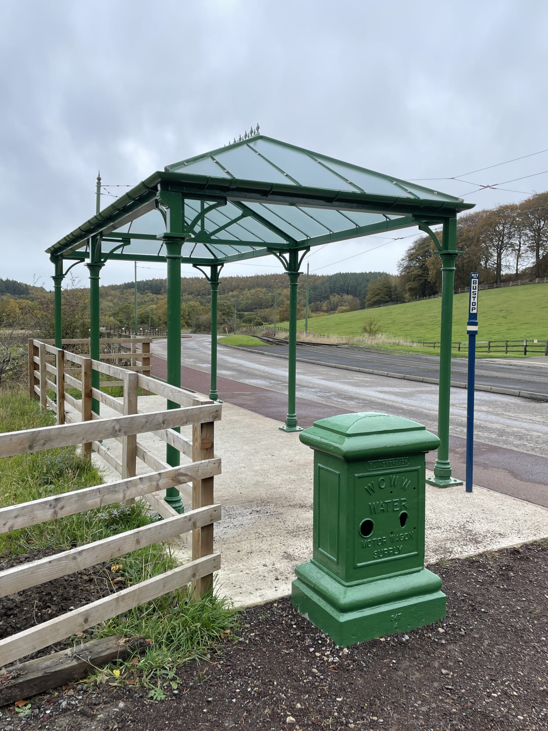
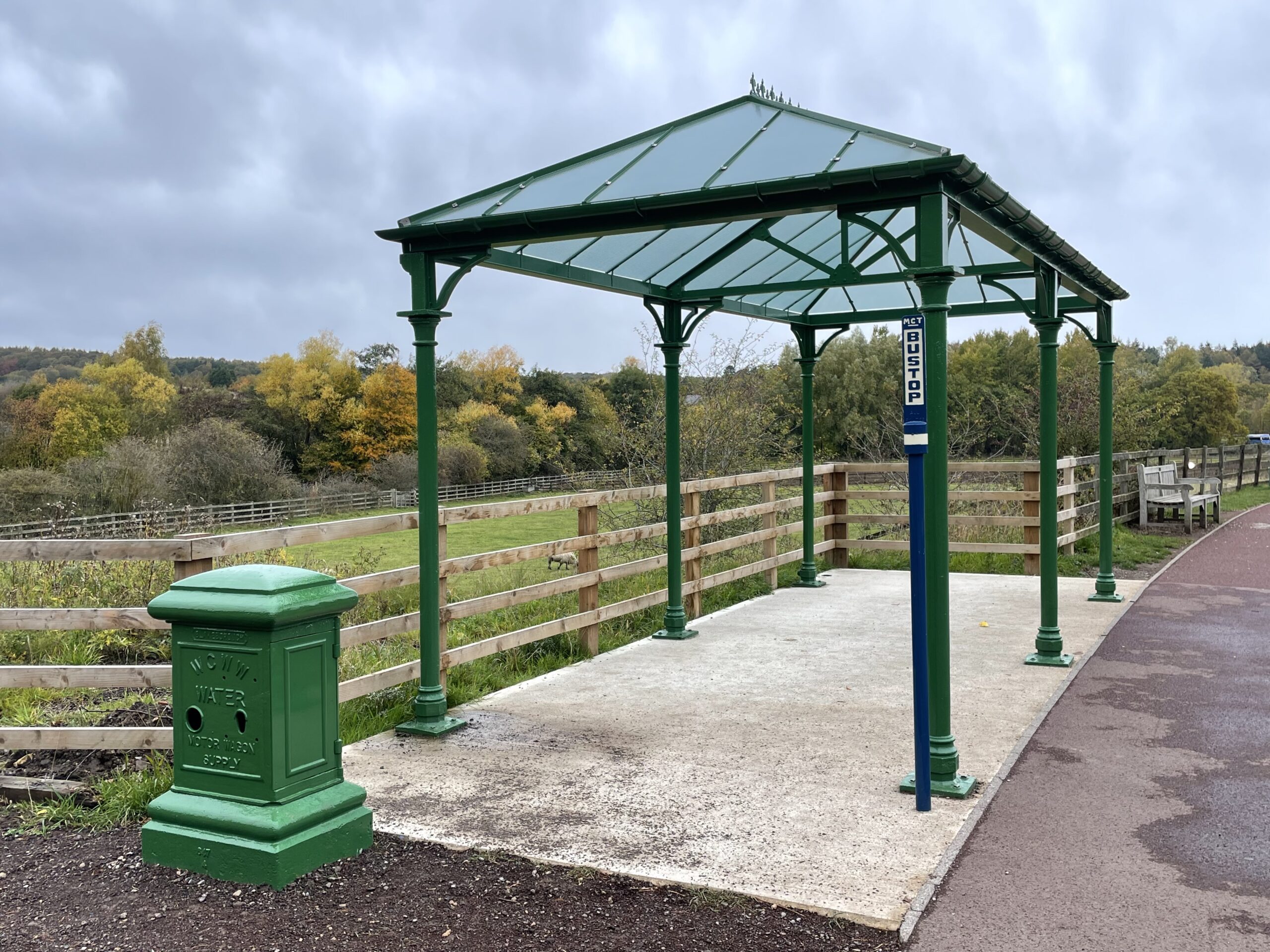
It’s very pleasing to get at least a few objects that have sat out of sight for so long, into a condition suitable for inclusion in the wider open air museum and performing a useful function once again.
Below: The track team are replacing sleepers on the Colliery standard gauge line – so far they have tackled the shed road and part of the loop.
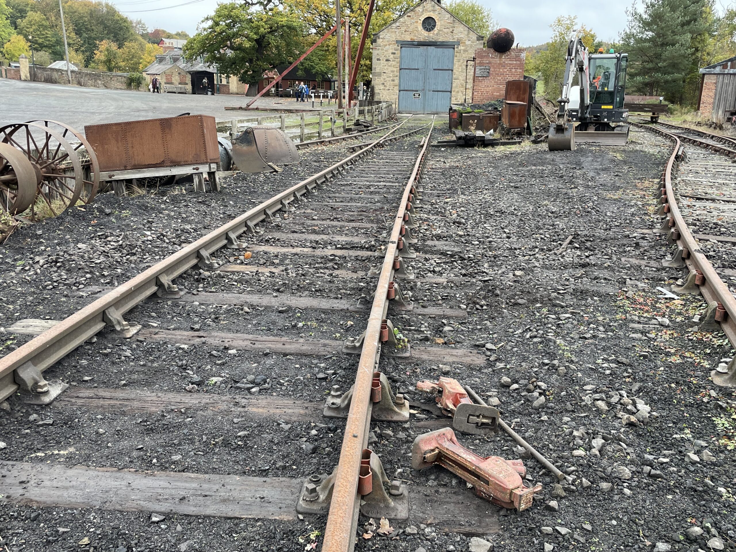
Photographs by Phil Doran, Luke Griffiths, Paul Jarman and Sam Telfer


Recent Comments