
Samson construction latest…
Its been a busy week! As the other recent posts reveal, activity can come in bursts, and last week was no exception for Samson, with significant progress being made on its construction.
Below: At Beamish, the footplate has now been attached to the frames, fitted bolts being used in this ‘final’ sequence. As a result further painting has been possible while Dave assembles and completes the brake gear. We have blocks on both sides, though the original probably only had them on the offside – due to the position of the gear wheels on the nearside – to mix rail and road terms!


Below: The rear bufferbeam is in place and has been treated with linseed oil (the timber is oak) to match the front one. The rods are in place and the frames have been rolled back and forth to identify any binding or tight spots – there being one slight one on one rod bush. Which is excellent news and a great credit to Dave and Statfold Barn’s engineers – neither party having met each other but both clearly at ease with the drawings Dave created and the principles of sound engineering. The rods have been removed for some further work and to enable me to paint the wheels more easily.

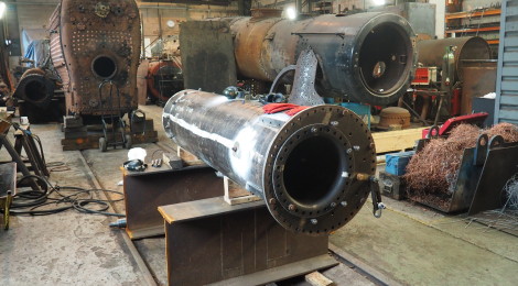
Below: Meanwhile, over at Bridgnorth at the north end of the Severn Valley Railway, Matt, Chris and I assembled last Tuesday for three days of riveting. With the SVR’s Duncan Ballard at hand, we were able to make use of the fantastic boilershop facilities to prepare then rivet numerous parts of the boiler assembly. Here is the boiler barrel looking very small indeed amidst a range of standard and narrow gauge locomotive vessels.

Below: Each section to be riveted has to be tightly bolted in place, leaving every other hole clear to enable reaming of the plates as a pair – they aren’t separated again after this process, which involves moving each bolt around one hole to ensure no movement, then reaming of the holes that previously contained bolts. Here Matt is reaming the front tubeplate angle holes using the air tools favoured for such work.

Below: A close up of the reamer as it finds its way through the already drilled plates, creating a uniform hole.

Below: Chris is seen counter-sinking holes – this was needed for a number of flush rivets (that could not stand proud of the plate) and also on every hole, to take the sharp edges away that might otherwise propagate cracks in the future. A mag-drill is used here, one that is magnetically attached to the plate being drilled (in this case the backhead).

Below: The inner firebox is seen bolted and reamed, with each bolt about to move again – these were flogged up tight to ensure the closure of the flanged plate against the backhead.

Below: An oxy-propane torch is used to heat each rivet in a small hearth. Rivets are cut to length individually – 2 1/4 for snap heads (ones to have a dome each end) and 2 1/18 for those that were countersunk i.e. have a shallower profile on the ‘hammered’ side to aid caulking or clearance (or both).

Below: The rivet is uniformly heated to a ‘sun yellow’ state, before being whipped way with tongues and inserted into the reamed hole.

Below: Here the rear angle ring is being riveted, with the rivet inserted from the inside. The large silver cylinder is the jammer – which has a repeating action – this is air powered and expands to hold the rivet in place from the inside, then ‘repeats’ (hammers) to ensure a tight fit by the hot rivet.

Below: Once the jammer has done its work (in two or three seconds), the air hammer, wielded by Duncan, is applied to the hot stub. This has a fitting in the end which can be changed for varies shapes depending on the desired shape of the finished rivet head.

Below: Attaching the backhead to the inner firebox required some ingenuity and also the mounting block from the radial arm drill, in order to securely attach the firebox to something in order to resist the jammer from below and the hammer from above. Matt jams as Duncan hammers.

Below: A number of these rivets had to be flat in order to enable them to be ground flush as this area of the firebox is captive between the angle ring and the backhead plate.

Below: More reaming, this time as the angle ring is prepared for the backhead riveting – this being bolted in place just to the left of my hands in this photo.

Below: We left the boiler ready for another visit and another session – which will require a means of securing the jammer along the length of the boiler barrel. After this, tubing and fitting of two stays can take place.

Below: Here is the front tubeplate riveted in place.

As ever, for the next instalment of this project, watch this space!
Our thanks to Duncan and the team at Bridgnorth for accommodating us and putting up with our endless pestering for tools or use of the crane. The boiler will carry an SVR builders plate as part of the CE conformity, so it will be just like your fridge freezer, car or kettle in having this European manufacturing standard mark on it!


Recent Comments