
Gateshead 10 – Engineering update…
In this post, I hand over to Matt Ellis, Keeper of Transport, for a special feature on Gateshead 10, and the extensive engineering work that is being undertaken as part of its mechanical overhaul phase…
Here is the promised blog post which details the recent work taking place on Gateshead 10. It may well end up being the first in a series, where we will cover the more involved and intricate tasks being undertaken. We will of course continue to update readers in the general news posts too.
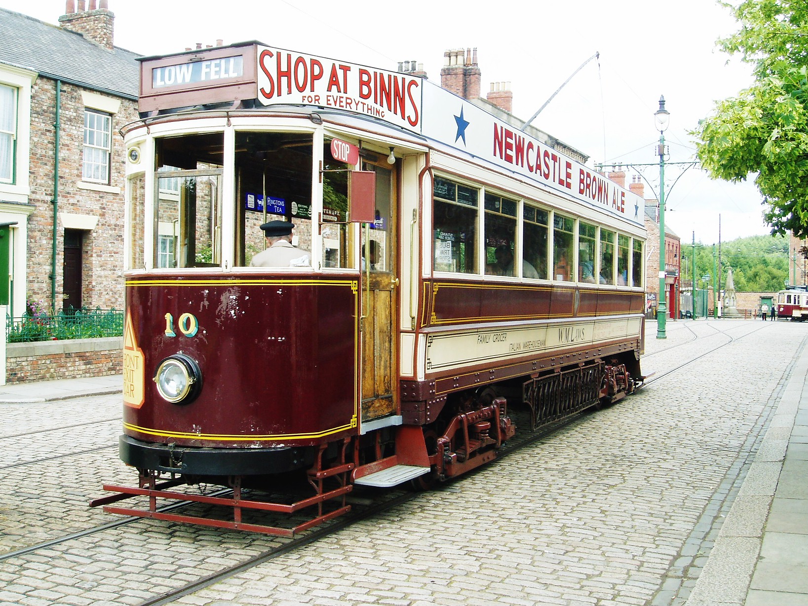
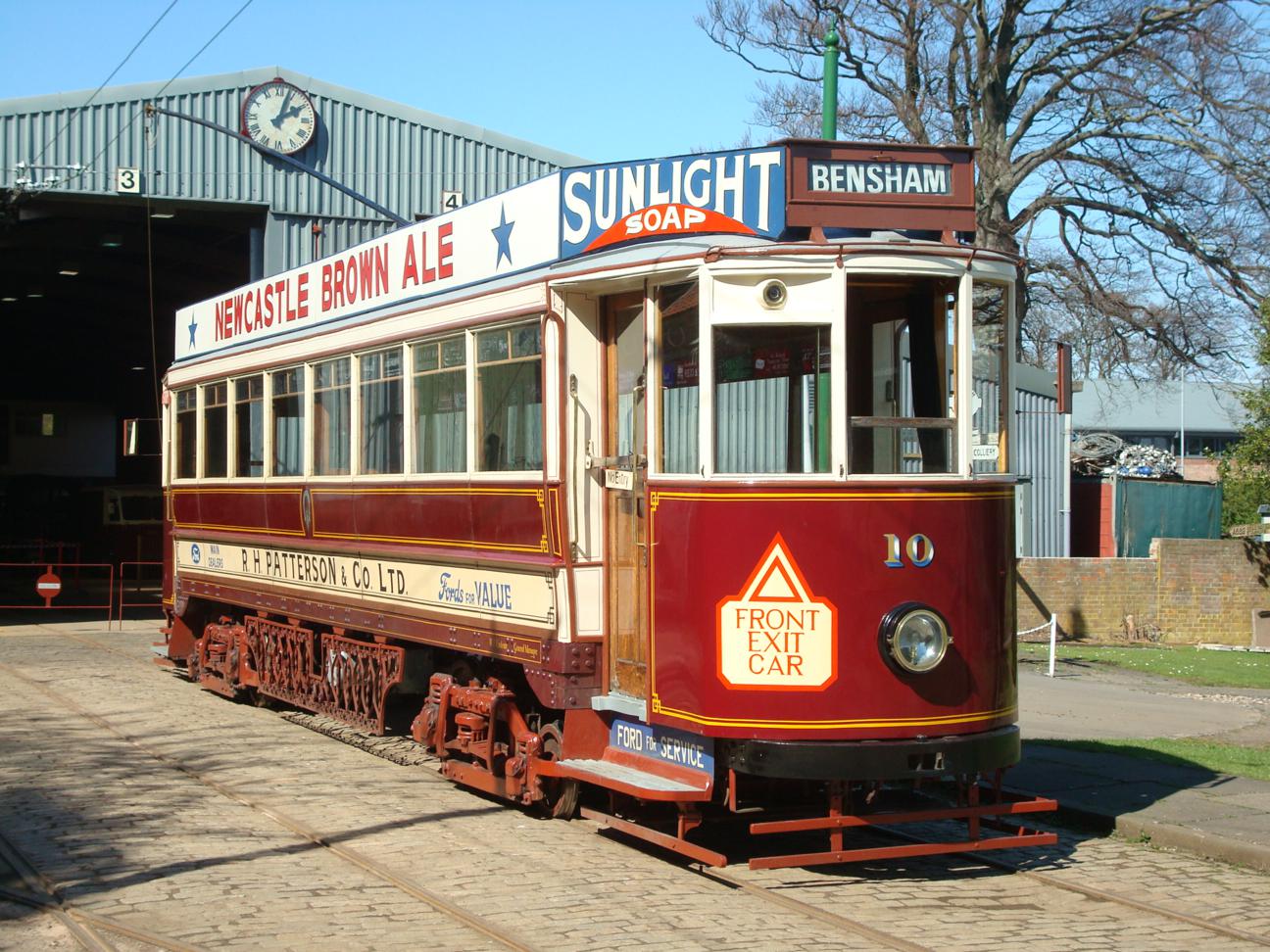
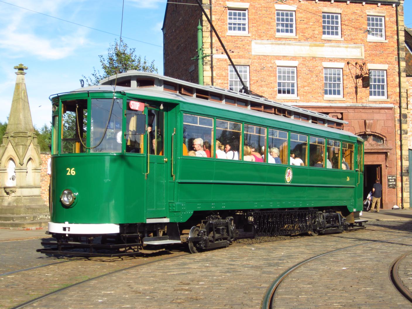
Below: We’ve become so accustomed to 10 being out of service, and prior to that, running in British Railways green livery , that a couple of photos to remind us of what it looks like in Gateshead livery may be timely! The plan is to reinstate the Gateshead livery, though initially without adverts (to ring the changes), though these will certainly be added later on.
The life of Gateshead 10 is well documented and we know we are the fourth owners (Gateshead Tramways, BR, the British Transport Commission and then Beamish). It is often possible to find drawings for the tramcars, or the trucks. Equally it is often possible to come across the maintenance records for the tramcars (and certainly railway locos) in service which detail work that was completed and the reasons for it. Where the trucks for Gateshead 10 are concerned neither of these routes to historic information have provided exact detail for the trucks under Gateshead 10. There are Brill drawings for the truck type we have, but these are for trucks which were fitted with tread brakes on both axles, whereas the trucks we have provide tread braking on the driving wheels only, along with track braking. Even so, the Brill information is of some use to us. The evidence on the trucks is that they have been extensively modified and rebuilt over the course of their life, unfortunately we have not been able to find details of when or why some of this work was done.
When we commenced the overhaul of Gateshead 10, we knew it would be an extensive job. Since then various contracts were let for work on and off site, to progress components. During that time, our in-house capacity has changed dramatically which will enable us to finish the work on the trucks now with very limited contract input. Whilst the contract work had focussed on individual components, Don and Zoe are able to look at the whole job and can therefore work out the best way to progress the work. The trucks (still in their heavily stripped down state) are the starting point, working to get them wheeled whereupon the other equipment (motors, brake gear and suspension) can be assembled. The wheelset positions in the truck effectively become the datum for all other work.
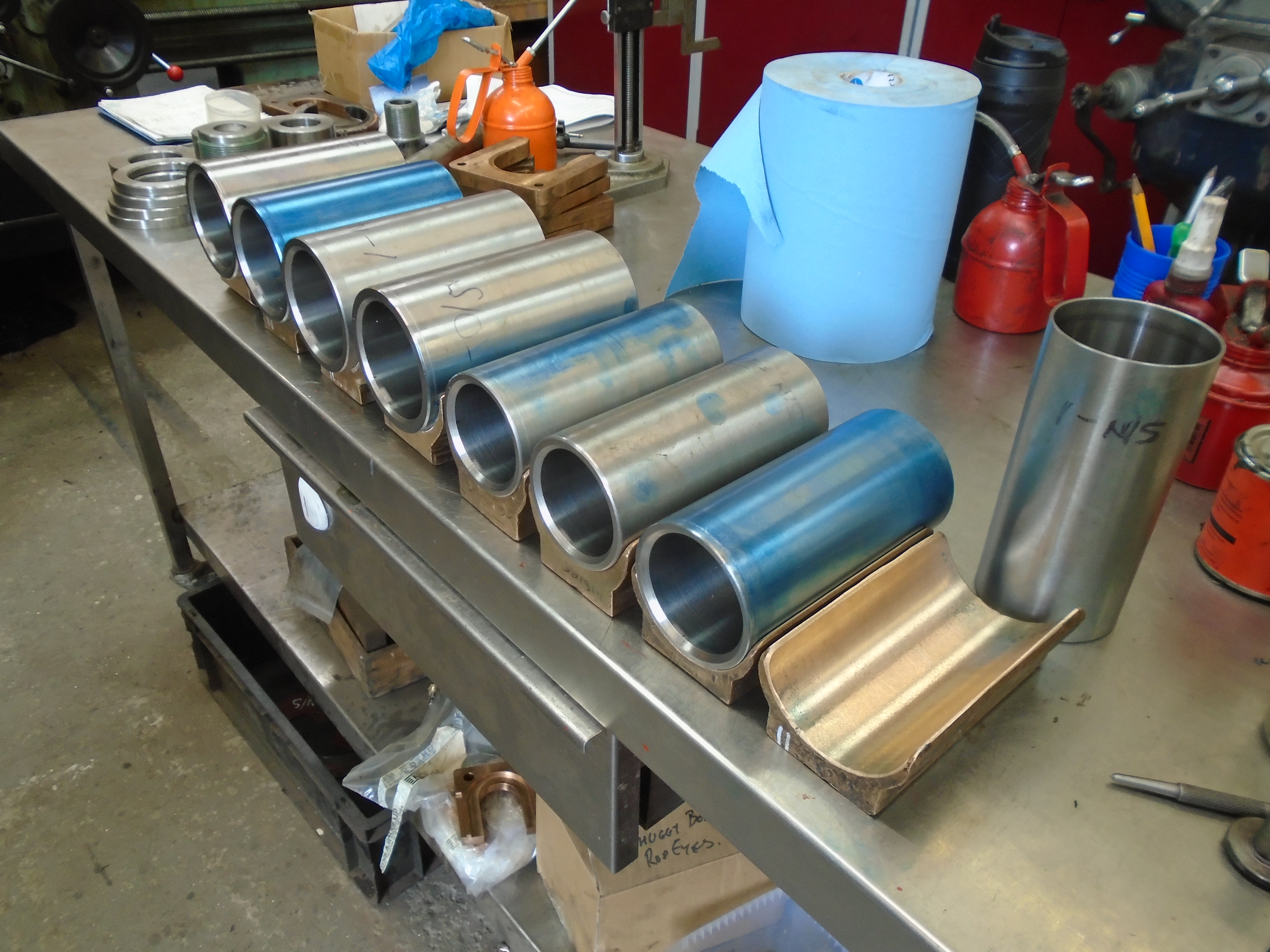
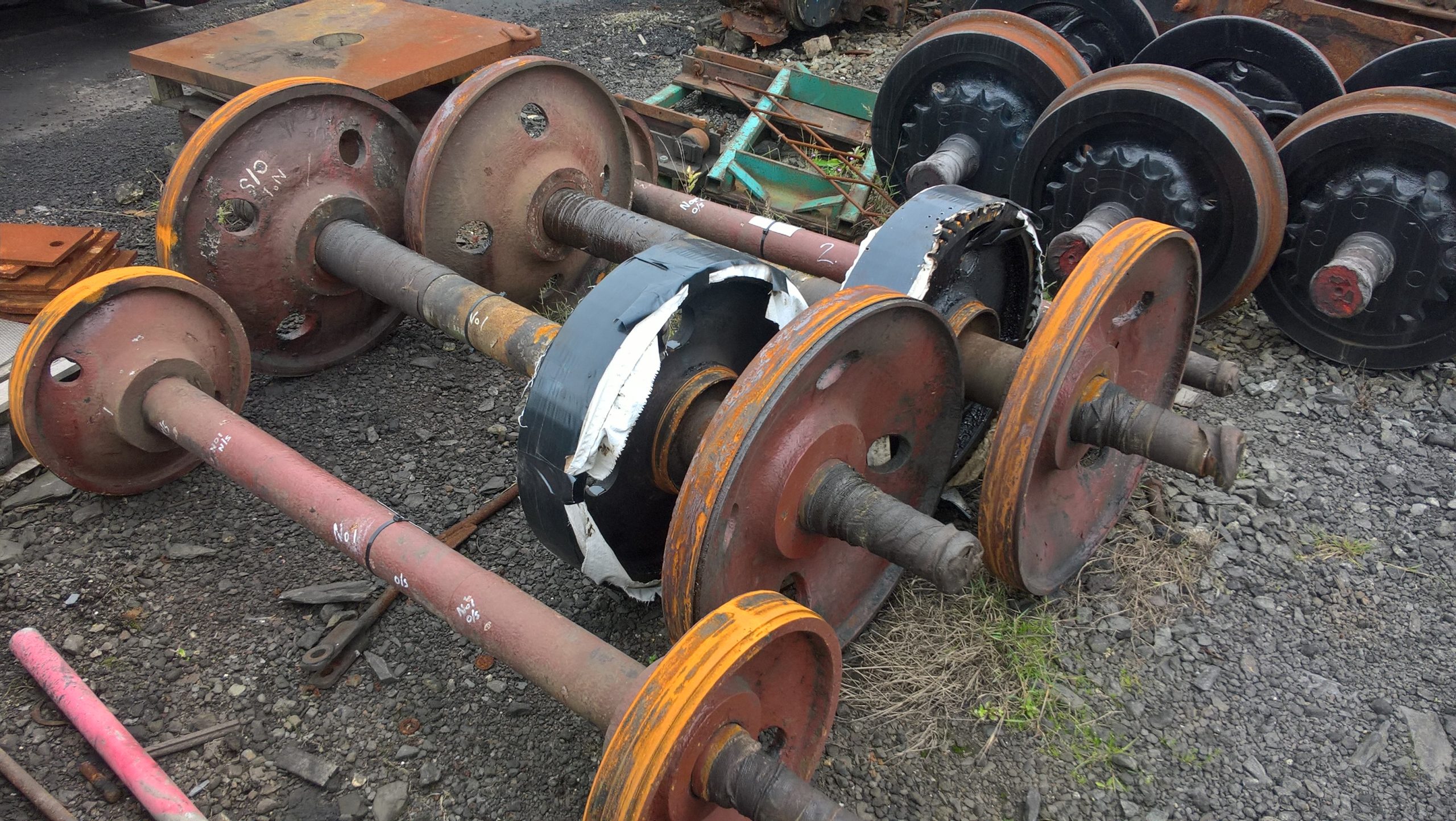
Below: The wheelsets themselves were re-tyred as one of the contract pieces of work. As part of this contract, the wheelsets needed the wheel centre castings machining to true them up with the axles before fitting the new tyres. When setting the wheelsets up in the lathe the centres in the ends of them were very shallow and needed machining themselves prior to the skimming of the wheel centres taking place. With a dose of hindsight this should have been a sign of things to come… Here three of the wheelsets are seen prior to skimming.
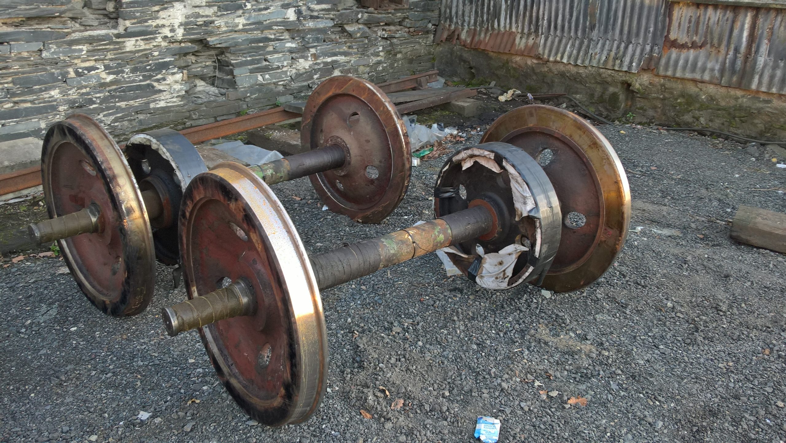
Below: With the work complete, the driving wheelsets are seen here complete with new tyres.
Work recommenced on the trucks earlier in the year, with Don and Zoe looking to fit the wheelsets into the trucks as the first task.
Below: This is a drawing of the axle ends prior to the 2006 overhaul to hopefully show the assembly and aid the reader for the remainder of the post. The journal is tapered (a little unconventional), then the groove carries a horse shoe thrust bearing which is retained by the collar and locates the position of the axlebox along the length of the axle.
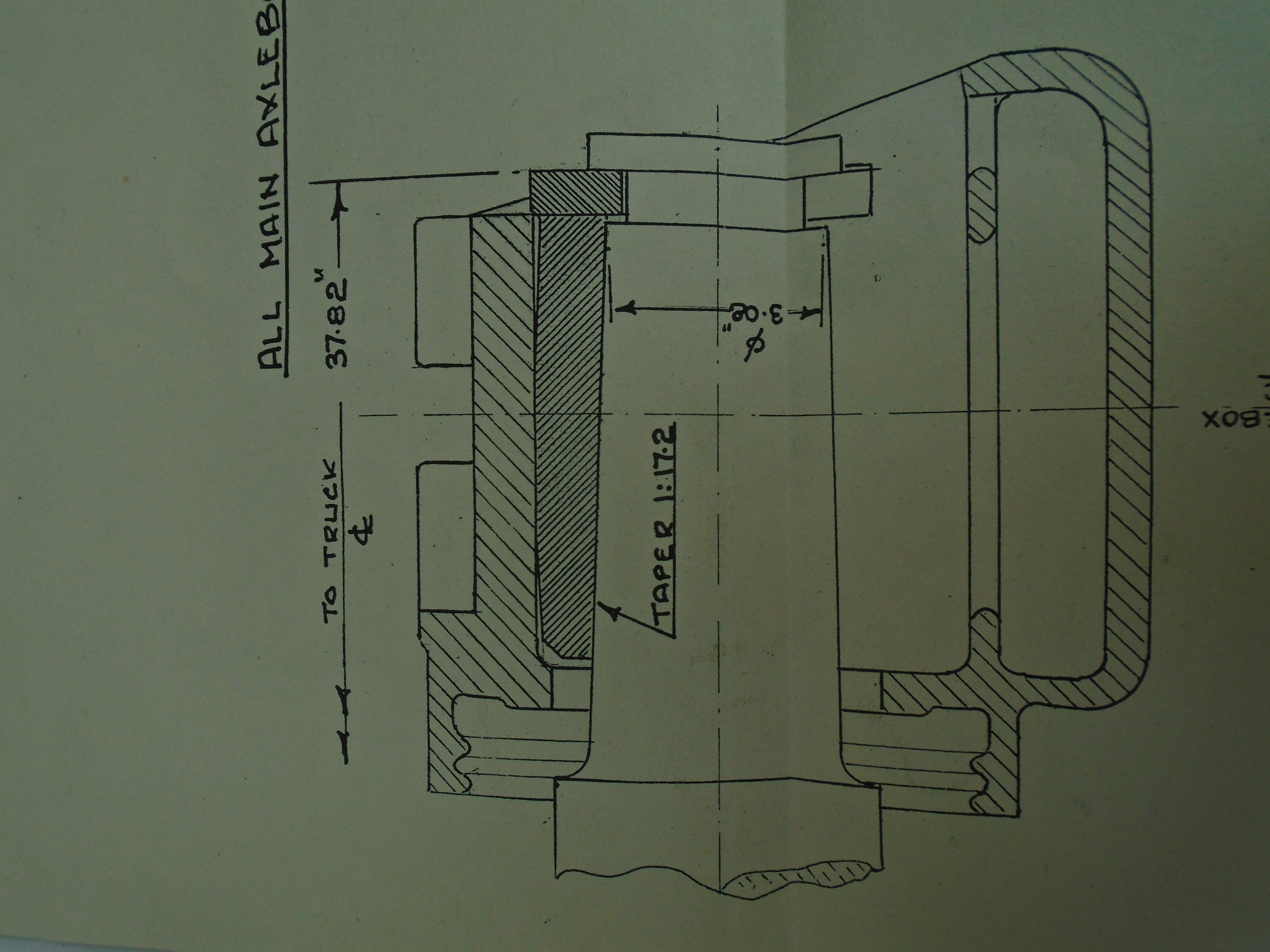
When in service Gateshead 10 had a reputation for running its axleboxes hot, and a ferocious appetite for the horseshoe thrust bearings which it literally ate. It appears the two were related, unsurprisingly.
Below: On the left is a seriously worn thrust bearing after 10 had helped itself to the majority of the material, on the right is a virtually new thrust bearing.

So far, what has been written above has been done so with the benefit of having lived through the work and providing a narrative that is understandable to the reader. We were not quite so lucky to have this as our starting point!
Below: This was our starting point. The photo shows a truck temporarily wheeled with the old horn faces (where the axlebox moves vertically) fitted, and the axlebox in. It was bordering upon impossible to insert the thrust bearings in both ends of the axle. Clearly it had run like this, but this explained the hot axleboxes and appetite for thrust bearings, as everything was under load even when static, rather than having running clearances. We needed to rectify this before we went any further, the only trouble was everything was pointing towards either the trucks being too wide or the axles being too short, highly unlikely to be the case surely?

The detective work commenced the following morning. A night to sleep on it left us with no doubt that whilst our conclusion was unlikely, it was the only plausible one we had to work with. Luckily, the Beamish Tramway Group kept extensive records of the work undertaken in 2006. The tram had been required back in service rapidly then, and whilst efforts were made to correct some of the same issue by narrowing the horn faces, it had not completely succeeded. A report had been completed at the time which explained the issue we were finding, along with some thoughts on why the axle journals themselves were tapered. The two best possibilities for the tapered journals were that either:
- The tram had run very hot at some point in its pre-preservation days and to remove the damage the journals had ben machined tapered with the desire to maintain full axle diameter near the wheel seat (where the wheel is pressed onto the axle).
- The journals were turned to a taper to trial a different form of bearing.
Without the historic records we will never know the actual reason. Also suggested in the 2006 report was that there may have been some material removed from the axle length at some point in the life of the tram. This was the light bulb moment, remember the need to re-machine the centres holes because they were too shallow?
Further investigation found dimensions from Brill for the axle lengths of various trucks, and as suspected ours were short. Not by much but enough. The next question was how to correct this.
With eight axle ends to attend to we wanted a solution that would work across all of them.
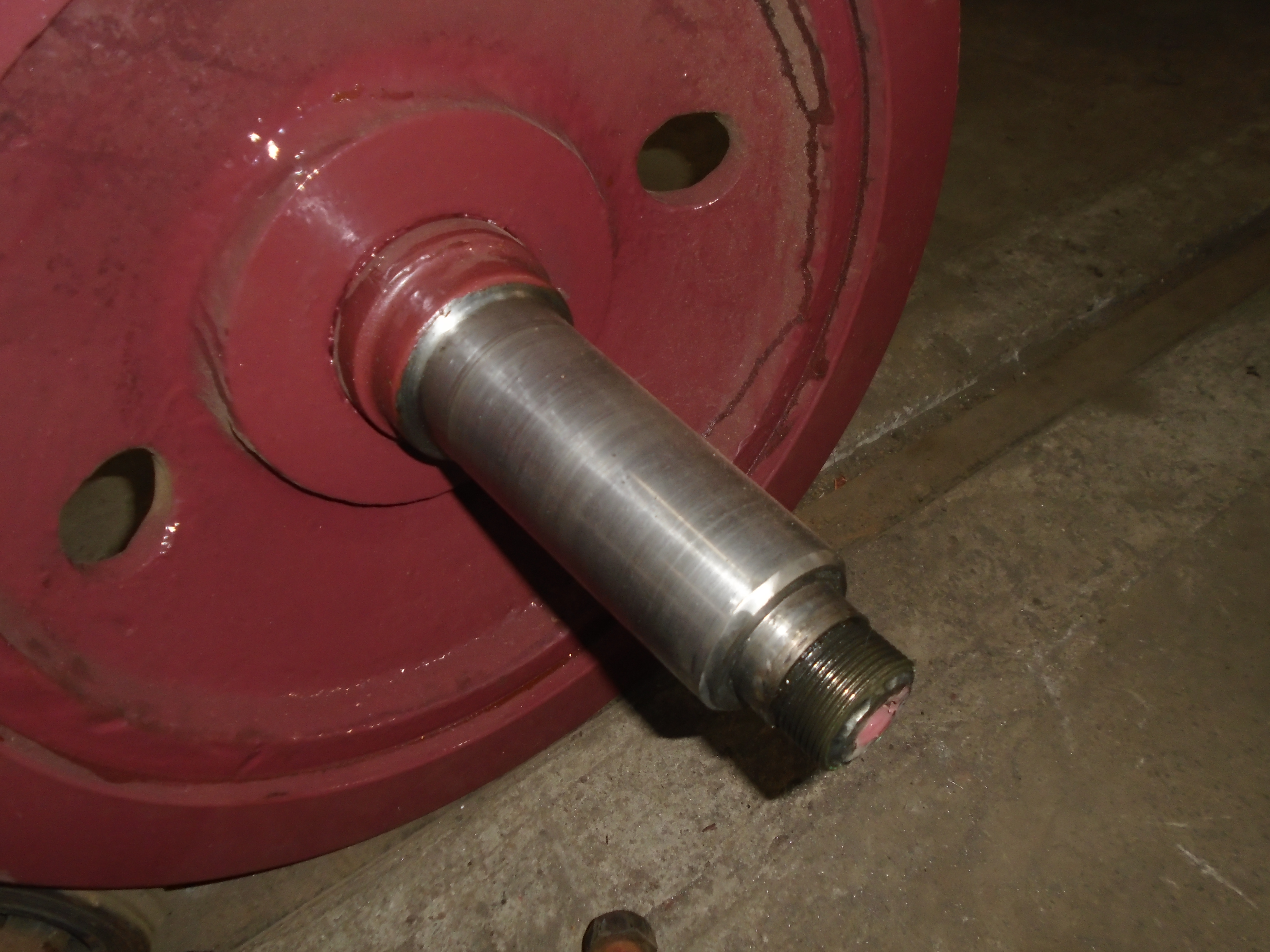
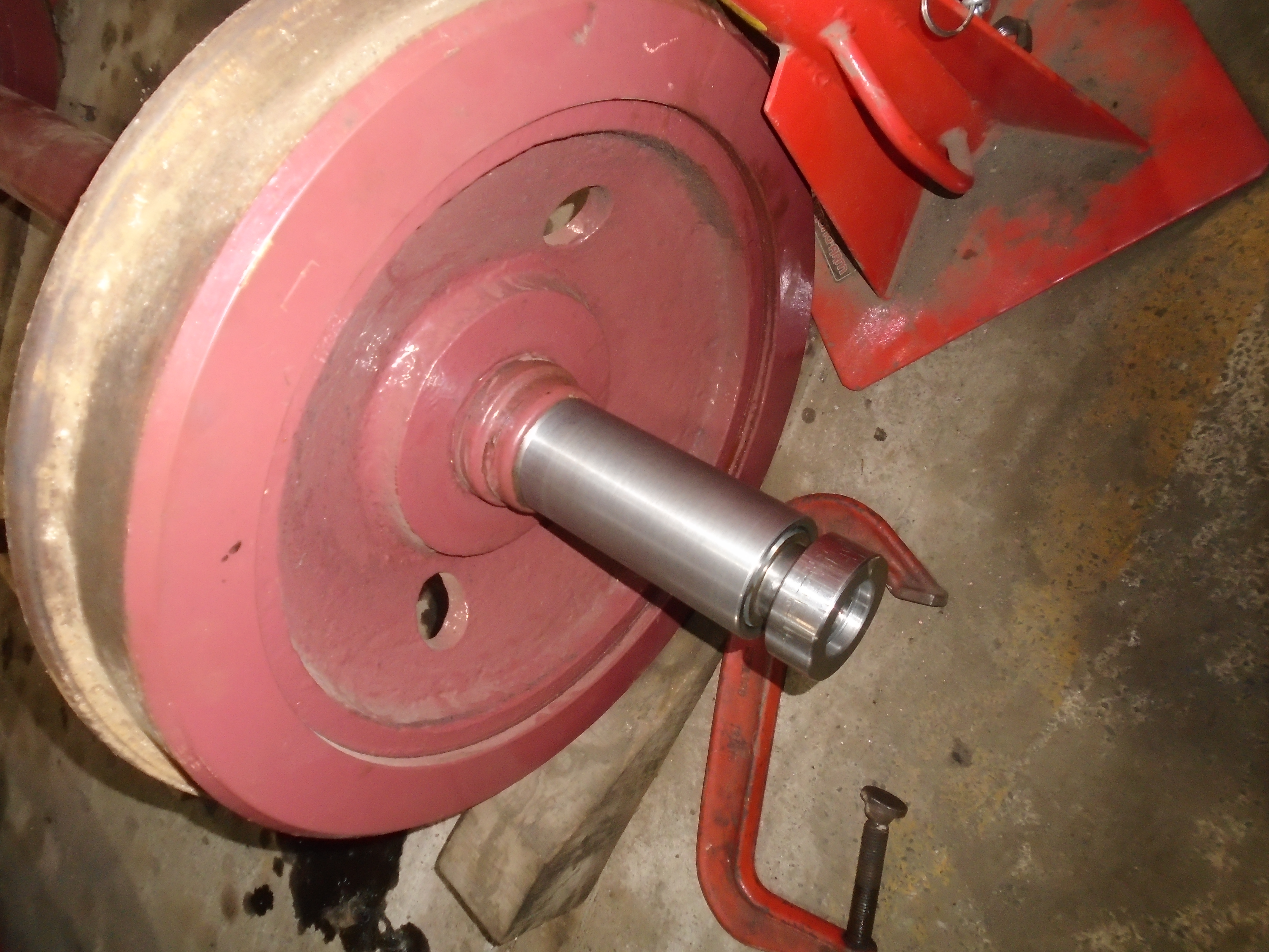
Below: This view shows an axle end with the collar removed. These collars are threaded, with a weld run around the inside of them to stop them from coming undone in service. By manufacturing new collars we can effectively move the groove on the axle along, and take up the space on the inside with a collar shrunk onto the parallel section, giving us axles with the correct distance between thrust faces.
At the same time as considering this we also took time to think about the unconventional tapered journals, and if these may be giving rise to problems themselves. Gateshead 5 is at the National Tramway Museum and on a few occasions in the past we have been permitted to examine the tram in detail. One of the detail differences on Gateshead 5 is that it has parallel journals. As well as this evidence, we know that the tapered journals give a number of potential issues:
- The small end of the taper is smaller than the thrust collar meaning it is very difficult to remove the axlebox brasses when the tram is assembled. On all other cars, this is a simple task and aids inspection and maintenance.
- The tapered brass against the tapered journal can lock up if the brass rides up the taper, much like a morse taper drill sleeve.
- The weight of the tram is going to encourage the brasses to run to the small end of the taper, thus forcing the thrust collar outwards.
Whilst we were already in quite deep with the work on the collars, we decided that it is worth the effort to put the tram back to conventional parallel journals by sleeving the journals. We want the tram to be reliable in service for a very long time, so whilst this is more work it is very much worthwhile.
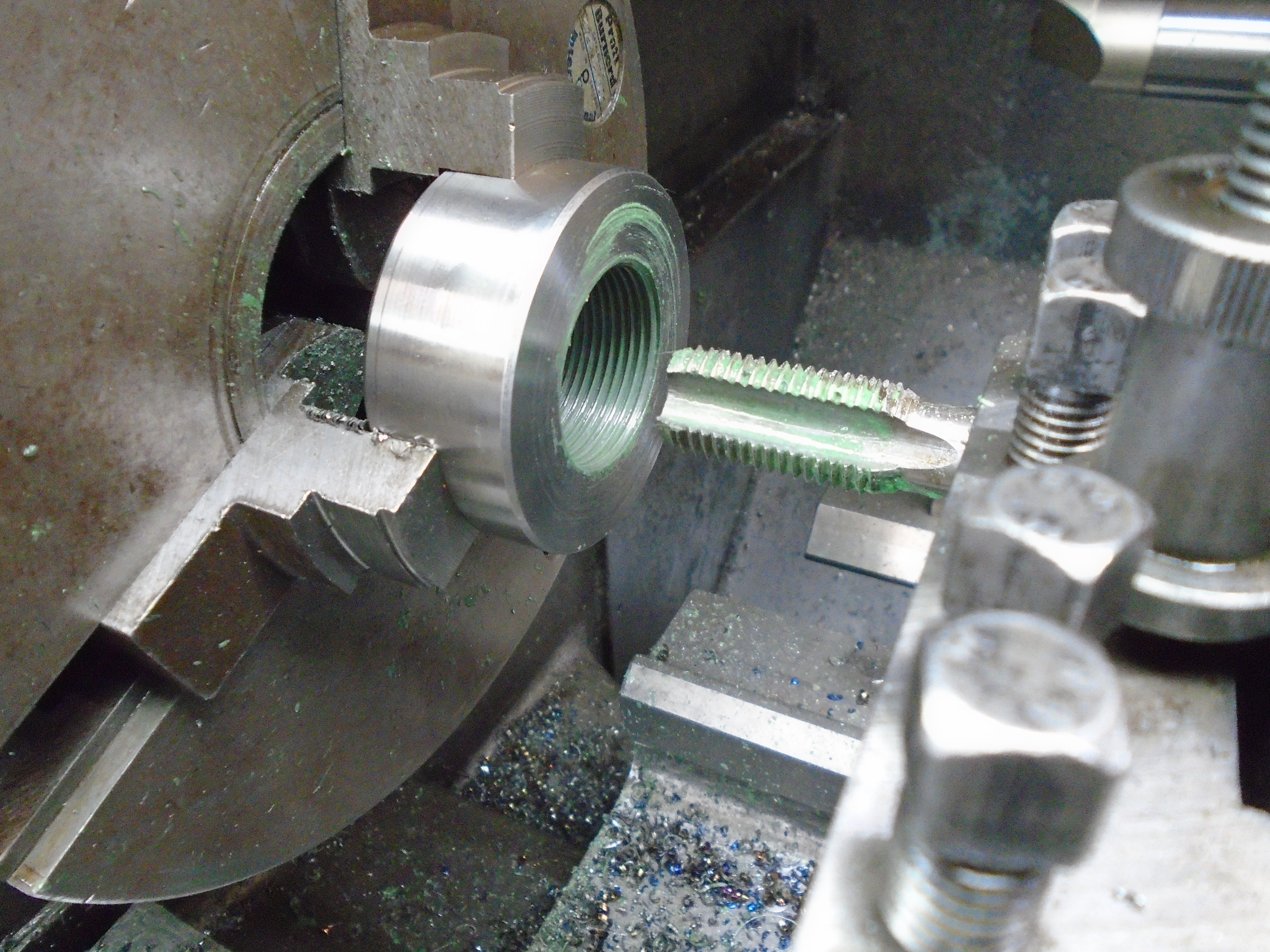
Apologies to regular blog readers here, you may now see photos which have already appeared. This time though, the full explanation of the work being undertaken is possible. Don machined the sleeves and the photos below show the raw material being drilled out, working up the drill sizes.

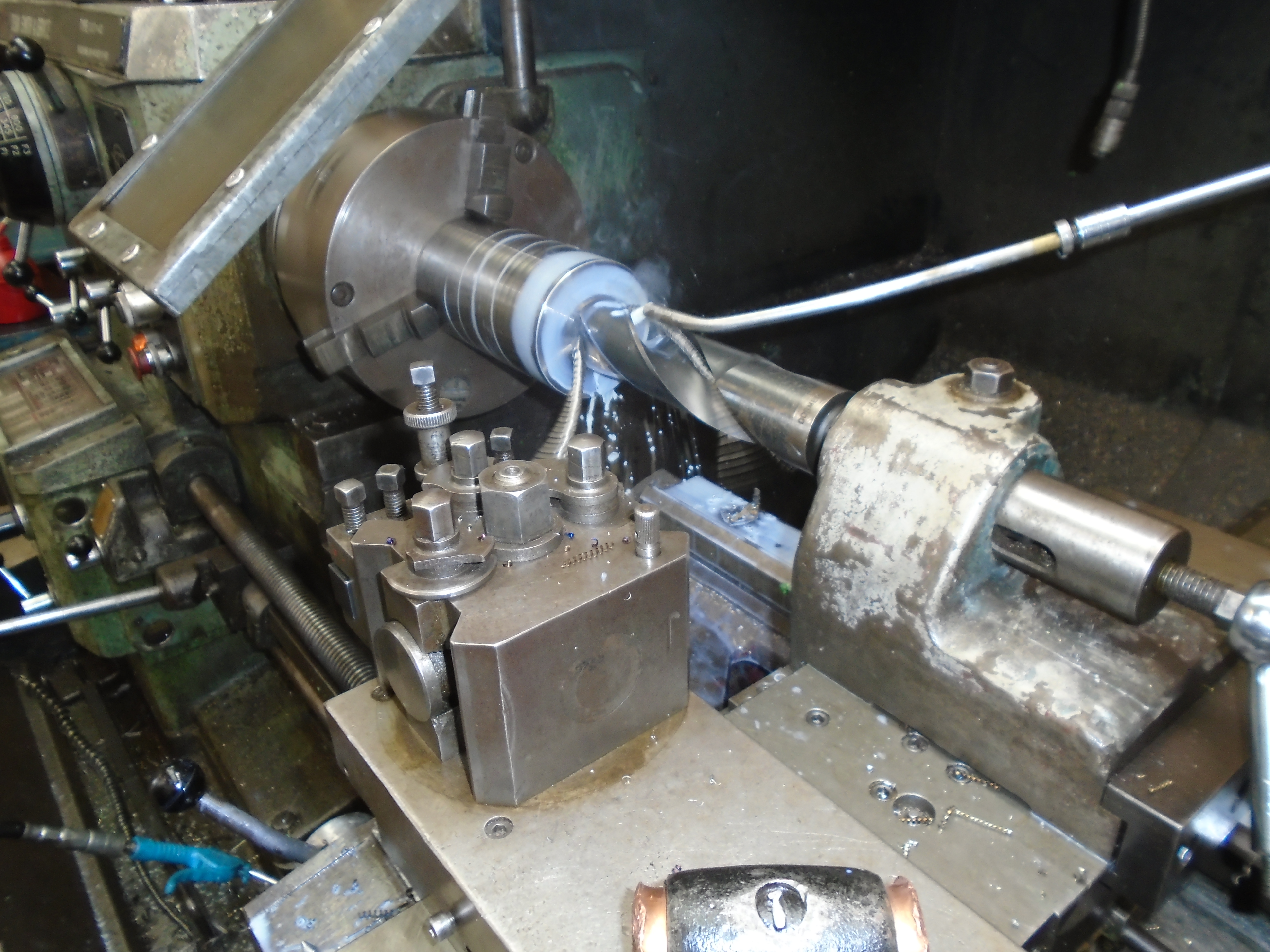
Below: Having reached the largest drill we have, Don then moved onto the boring bar to remove the last bit of material. The fixed steady is used to support the free end of the material, usually this would be done with a centre but obviously this isn’t possible when machining a bore. At this point, the bore is still parallel.
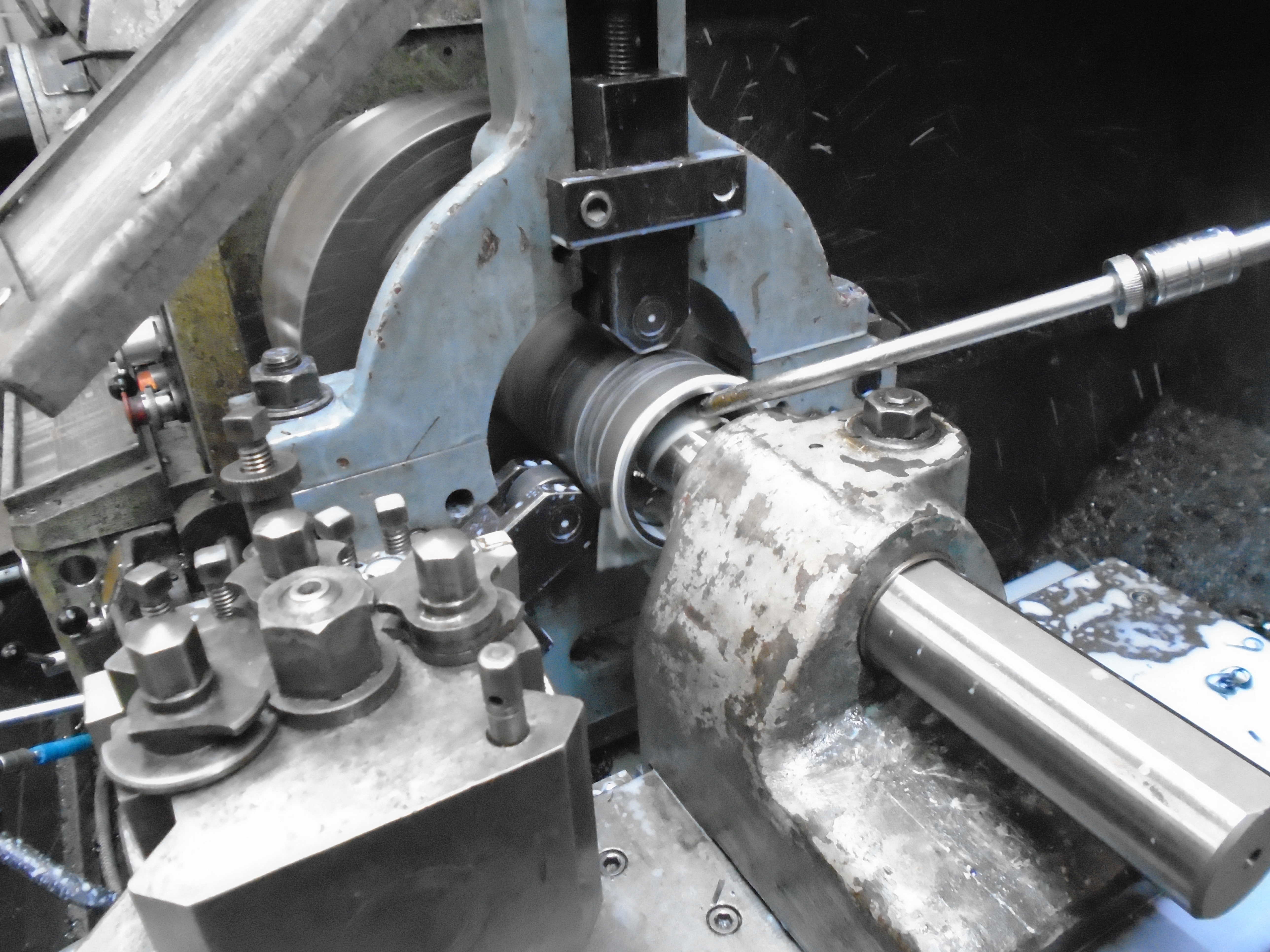
Below: The lathe has a taper turning attachment seen centre right of this photo, which can be precisely set up and causes the cross slide of the lathe to move at the desired angle as the cut progresses. There are advantages such as accuracy, surface finish and the ability to use the power feed, over using the compound slide for this work.
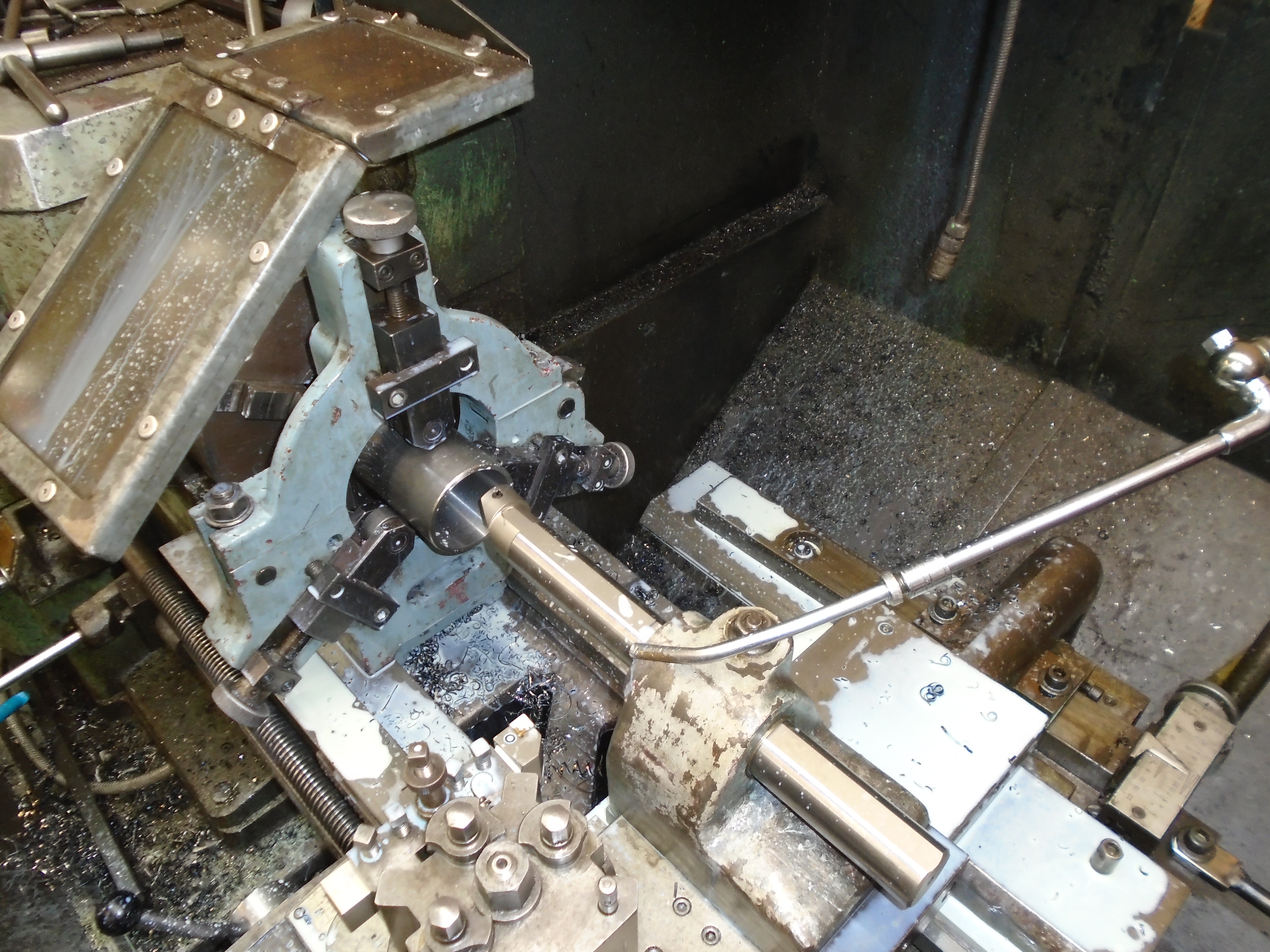
Below: The sleeves then had their outer diameter machined. Once complete, the brasses were bored parallel, with the sleeves being used to ensure the correct fit.
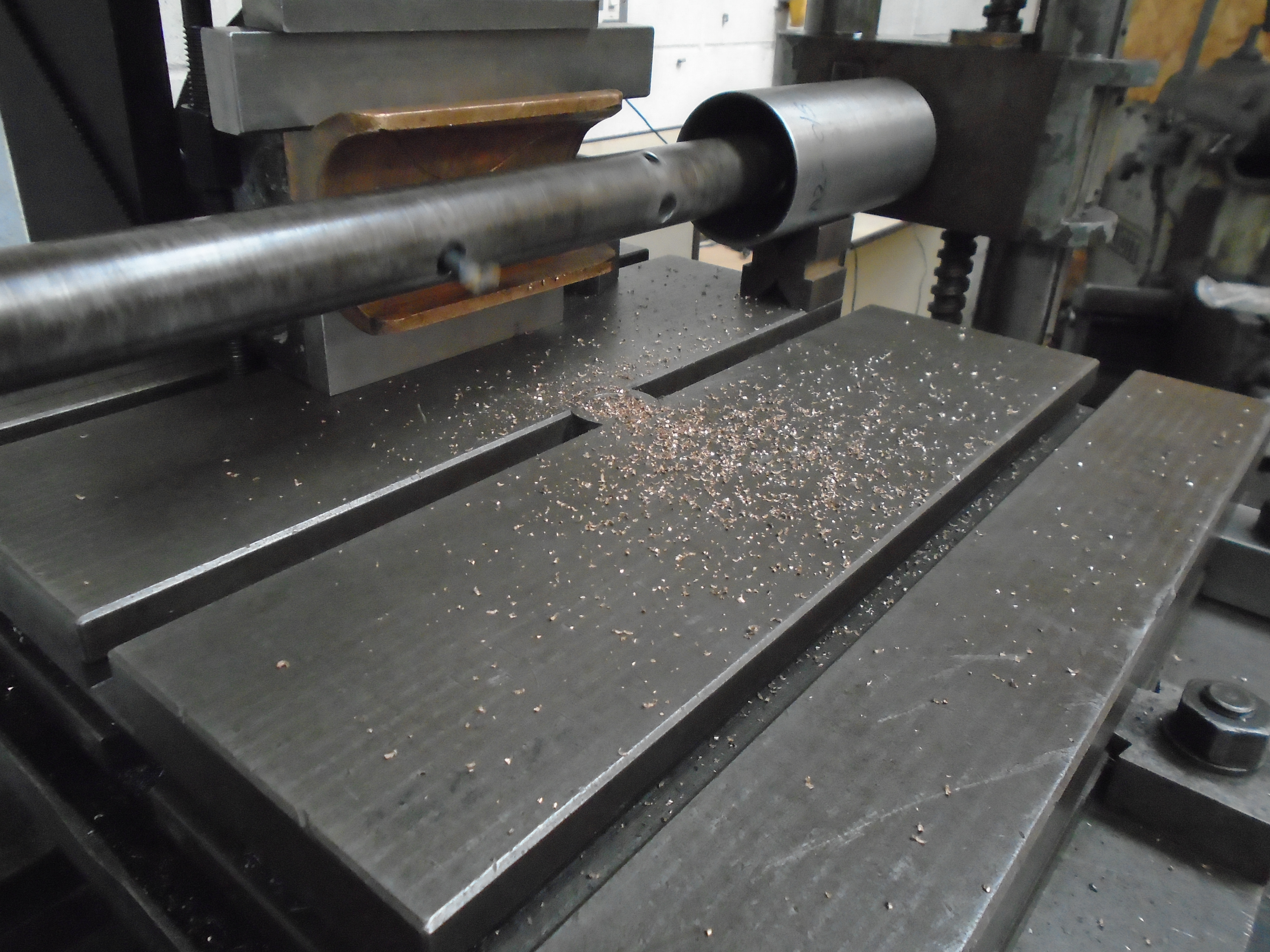
Below: The new threaded collars for the axle ends have been machined but the outer diameter and length left over size for now.
Below: A satisfying photo of eight completed brasses, eight completed sleeves and in the distance eight collars and eight shrink fit spacers.
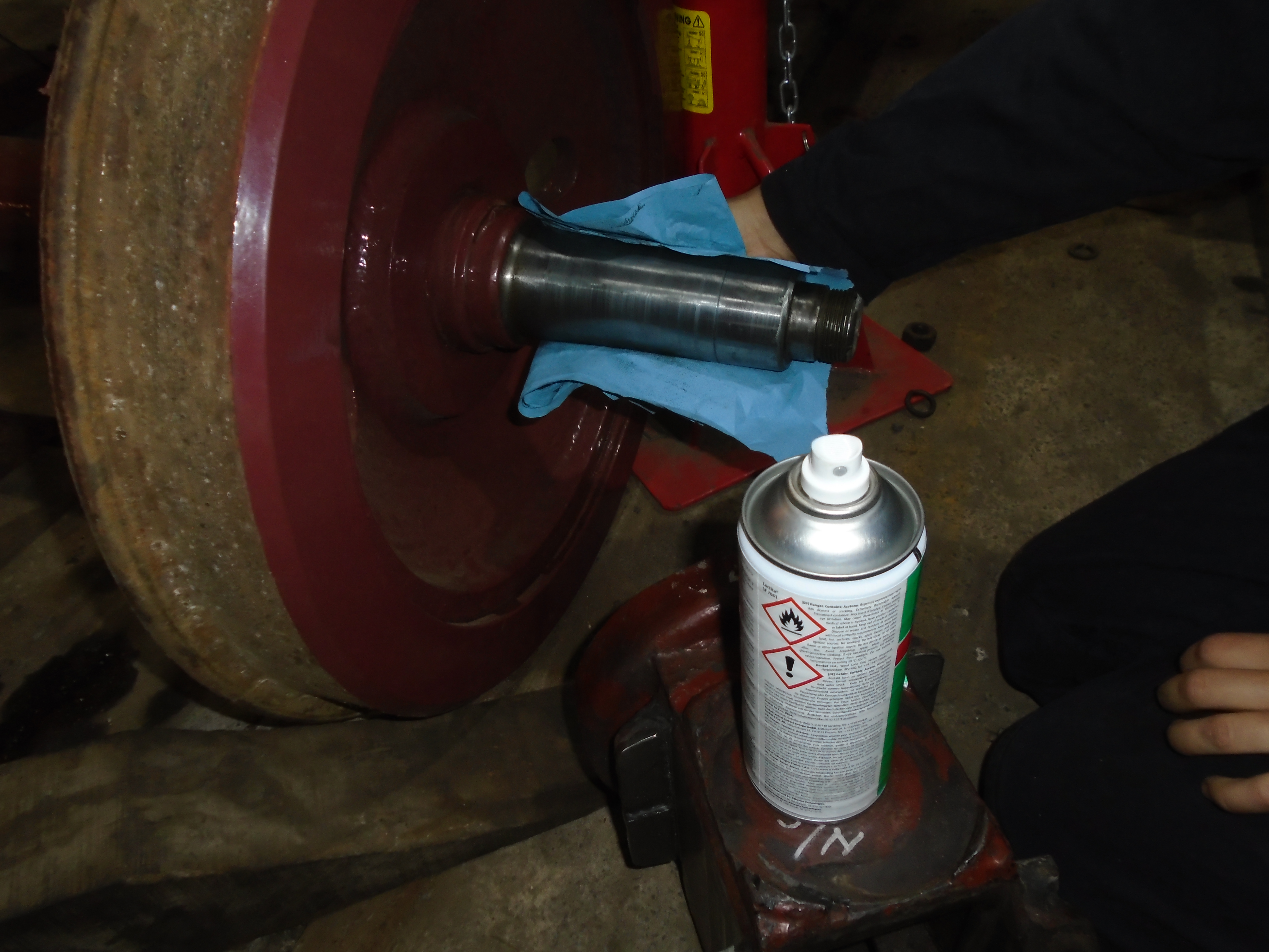
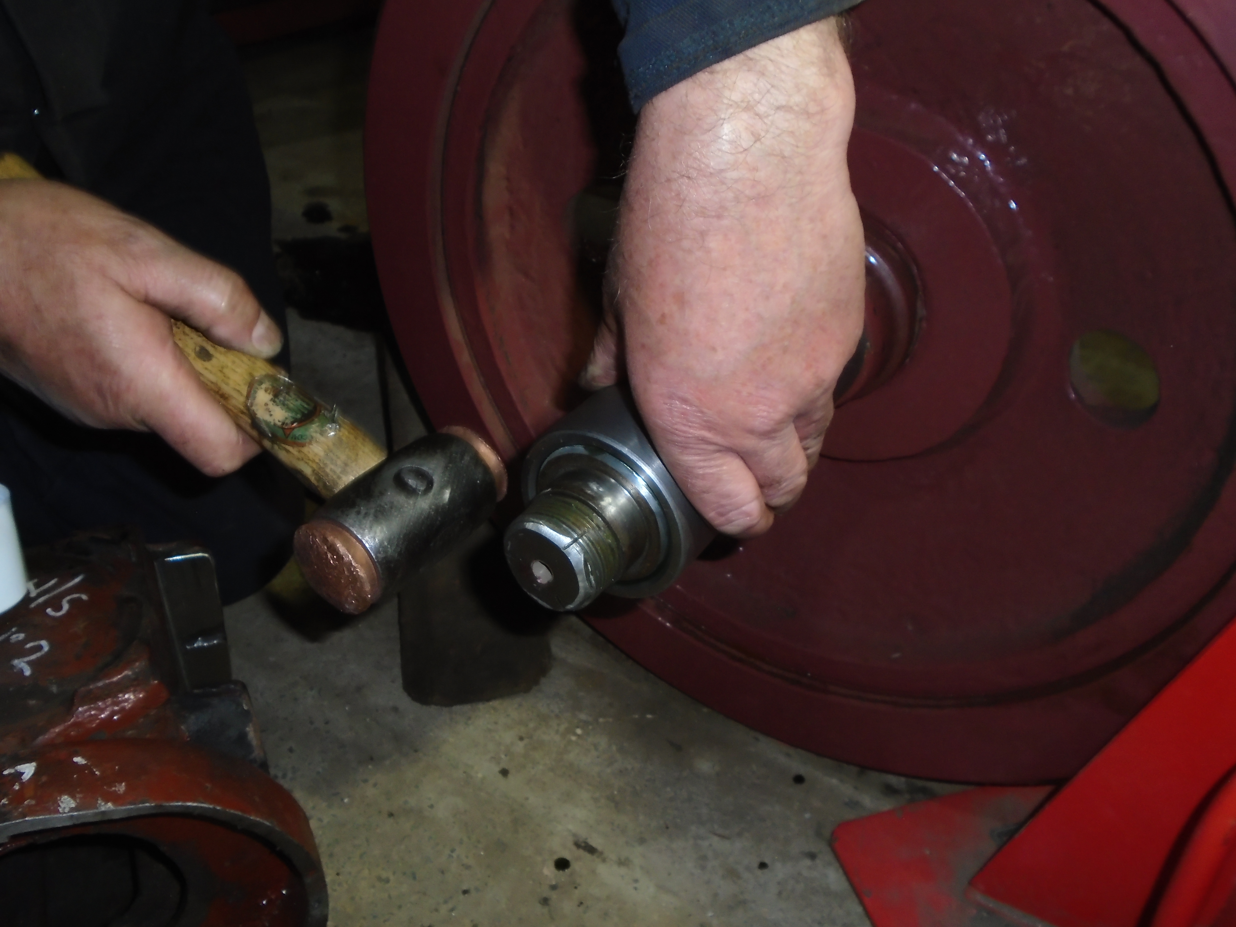
Below: The sleeves lock onto the tapers very well, but in addition to the interference fit, they will be fixed using Loctite with a small retaining weld at the ends. Here the axle is cleaned using the prescribed Loctite cleaner, the sleeve was similarly treated.
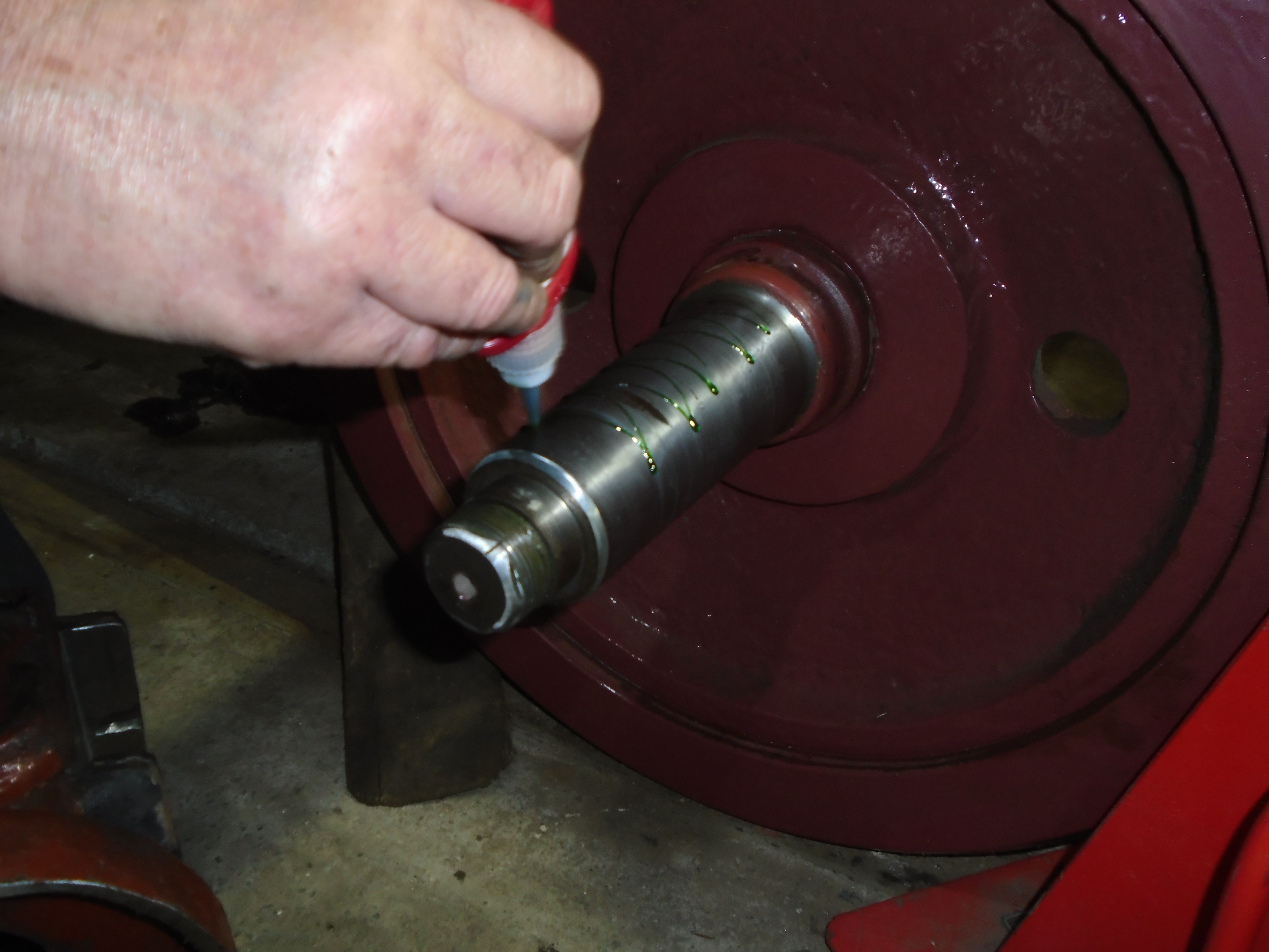
Below: The activator is then sprayed onto the axle and allowed to dry.

Below: The Loctite is then applied to the sleeve and axle

Below: The sleeve is then fitted, and lightly encouraged up the taper until it self-locks.
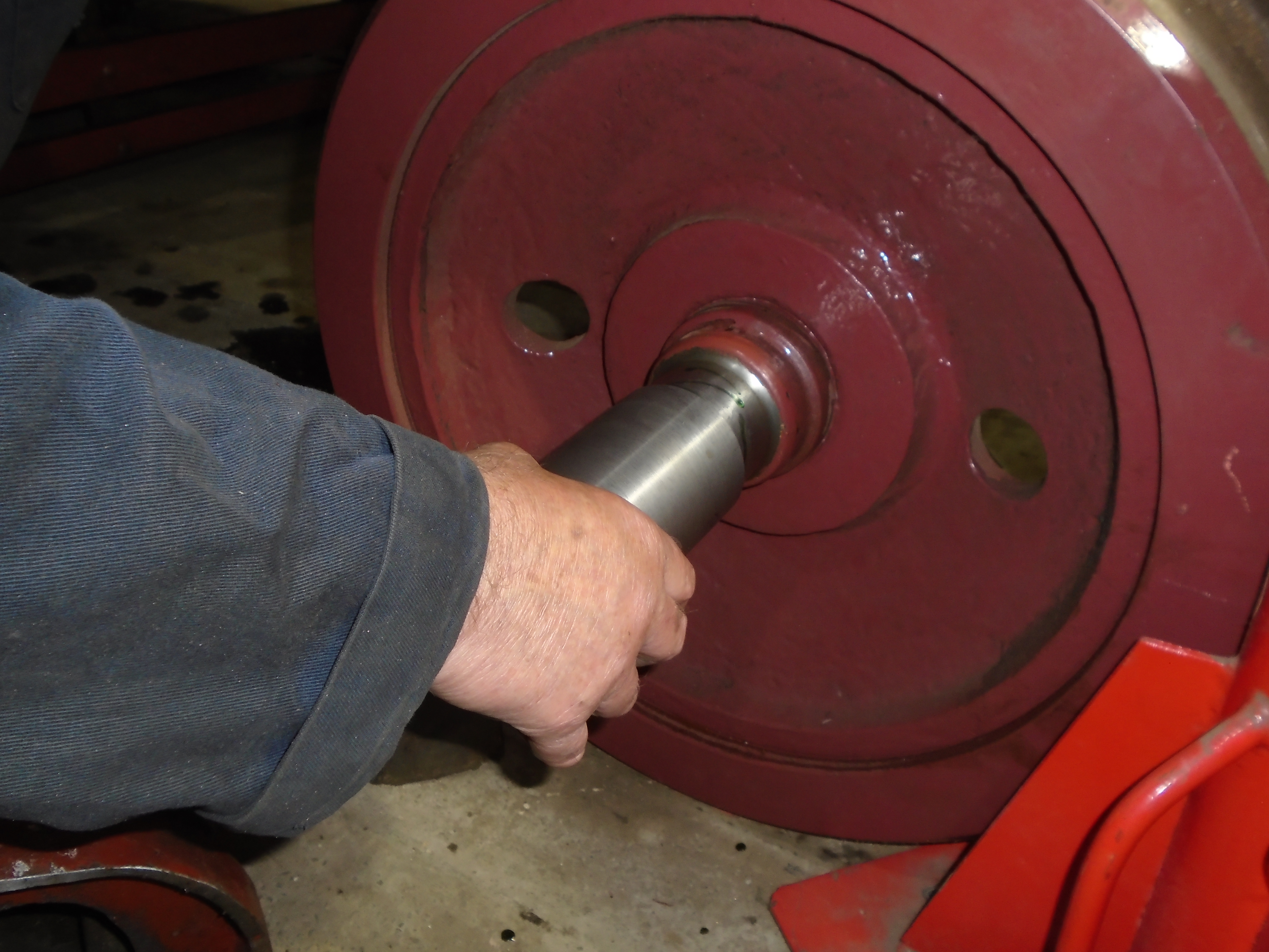
Below: The sleeve is then left for the Loctite to do its work and secure the sleeve to the axle, virtually permanently.
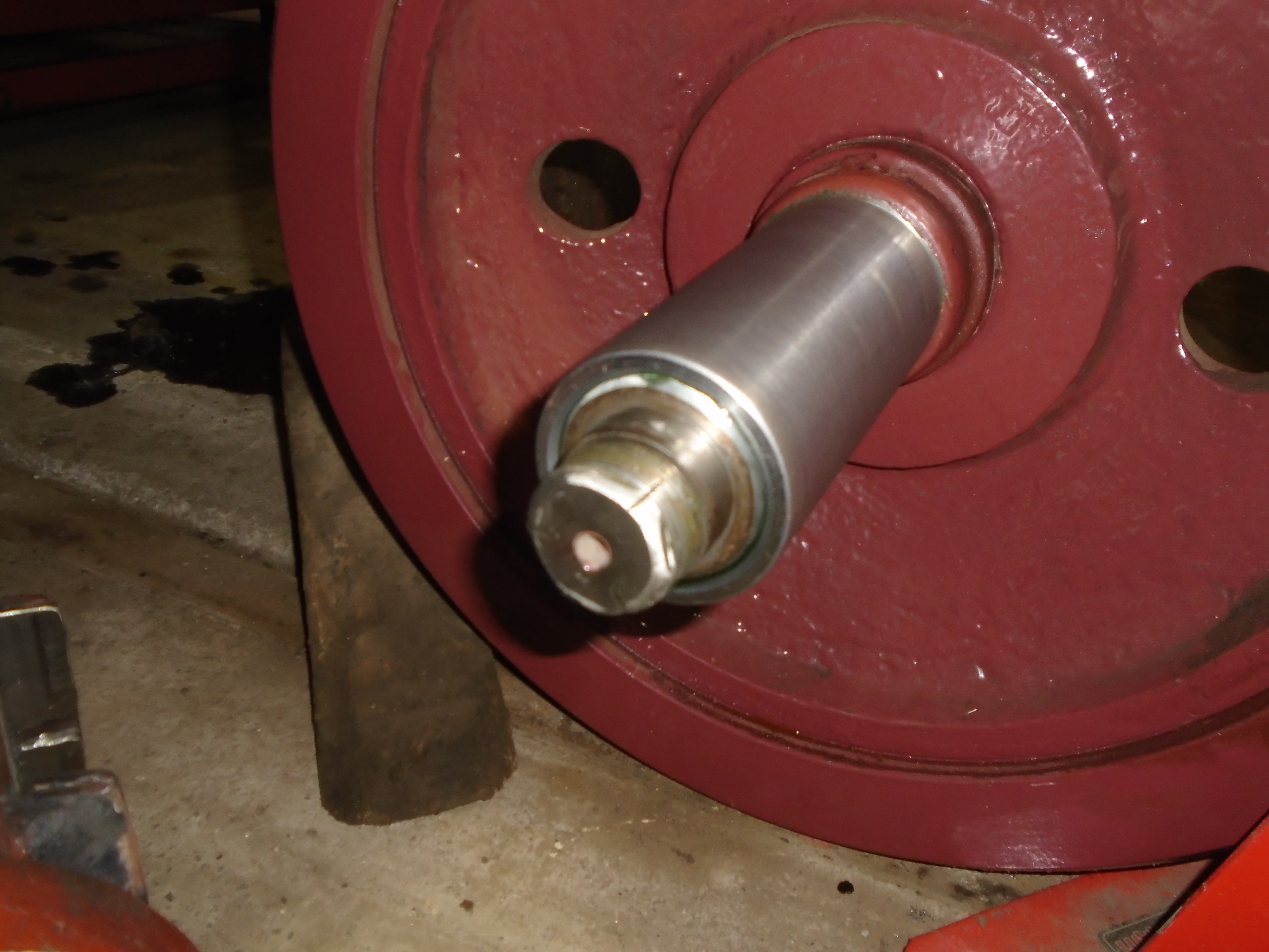
Below:- The collar is then fitted temporarily, without the spacer ring at this stage.
This is a suitable point to finish this update with some photos of the horn faces, which are being replaced, and which ties in with this work. Some of this work has appeared on the blog and small bits will do over the coming weeks.
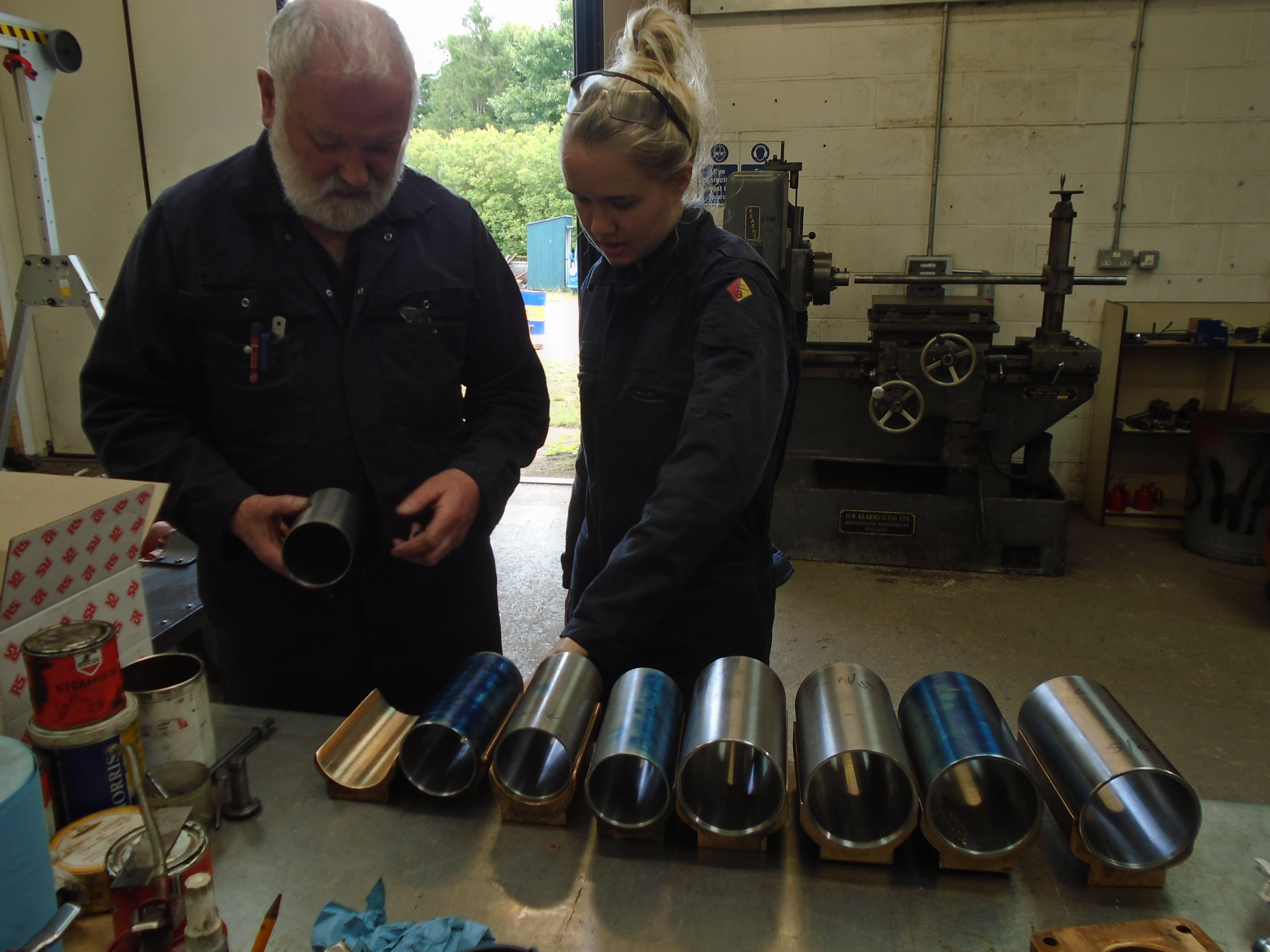
Below: Machining of the axlebox brasses for Gateshead 10 is now complete, mentor and apprentice seen here in discussion about the next steps.
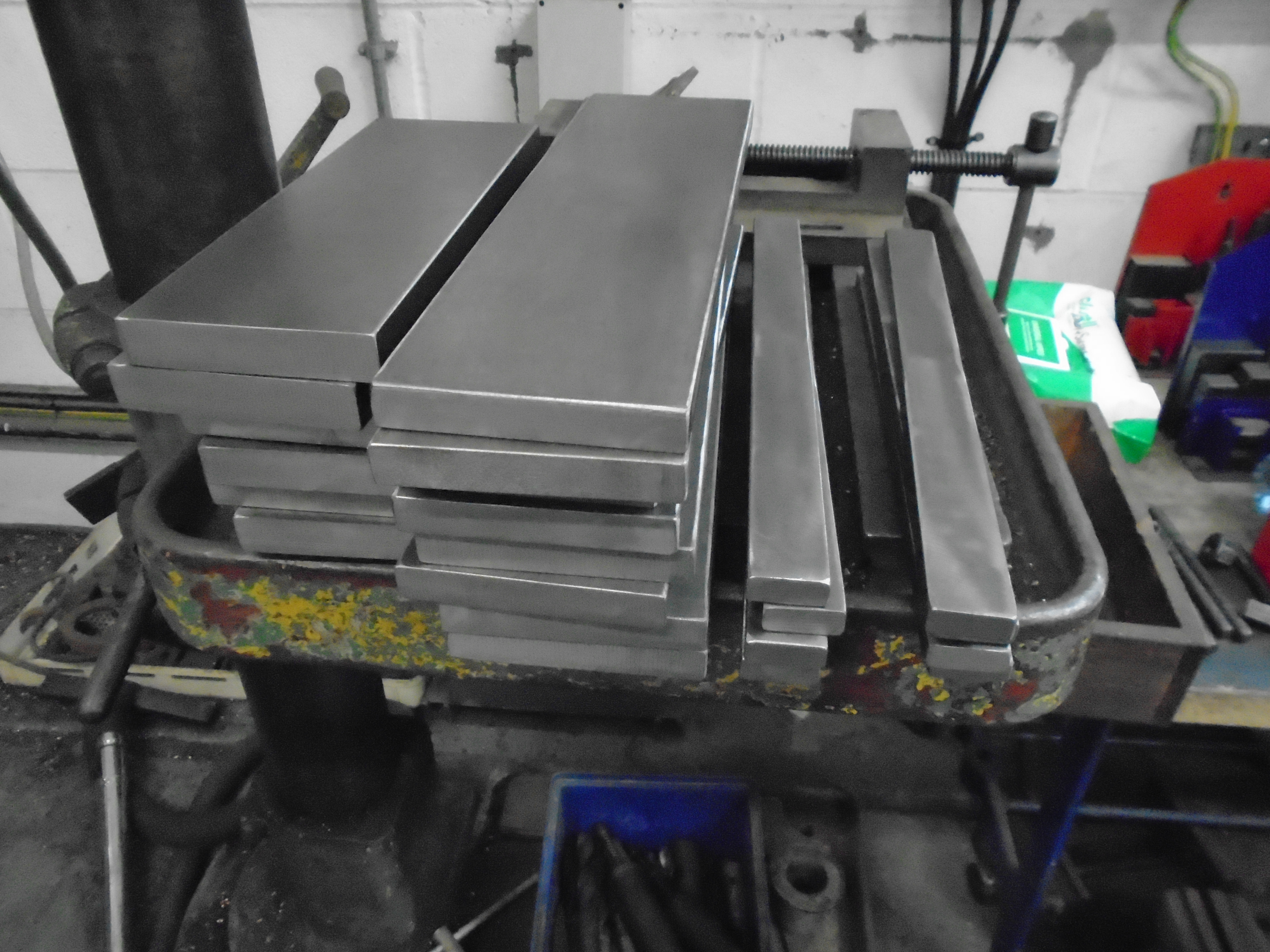
Below: Material for the next stage, quite an odyssey ahead here. These will become the new horn faces in the trucks, against which the axle boxes run up and down in the bogie frames. 16 of these in total, so 32 holes to drill, countersink and machine to square for the bolts, 64+ edges or faces to machine, 8 welds to be completed plus all the fitting entailed.
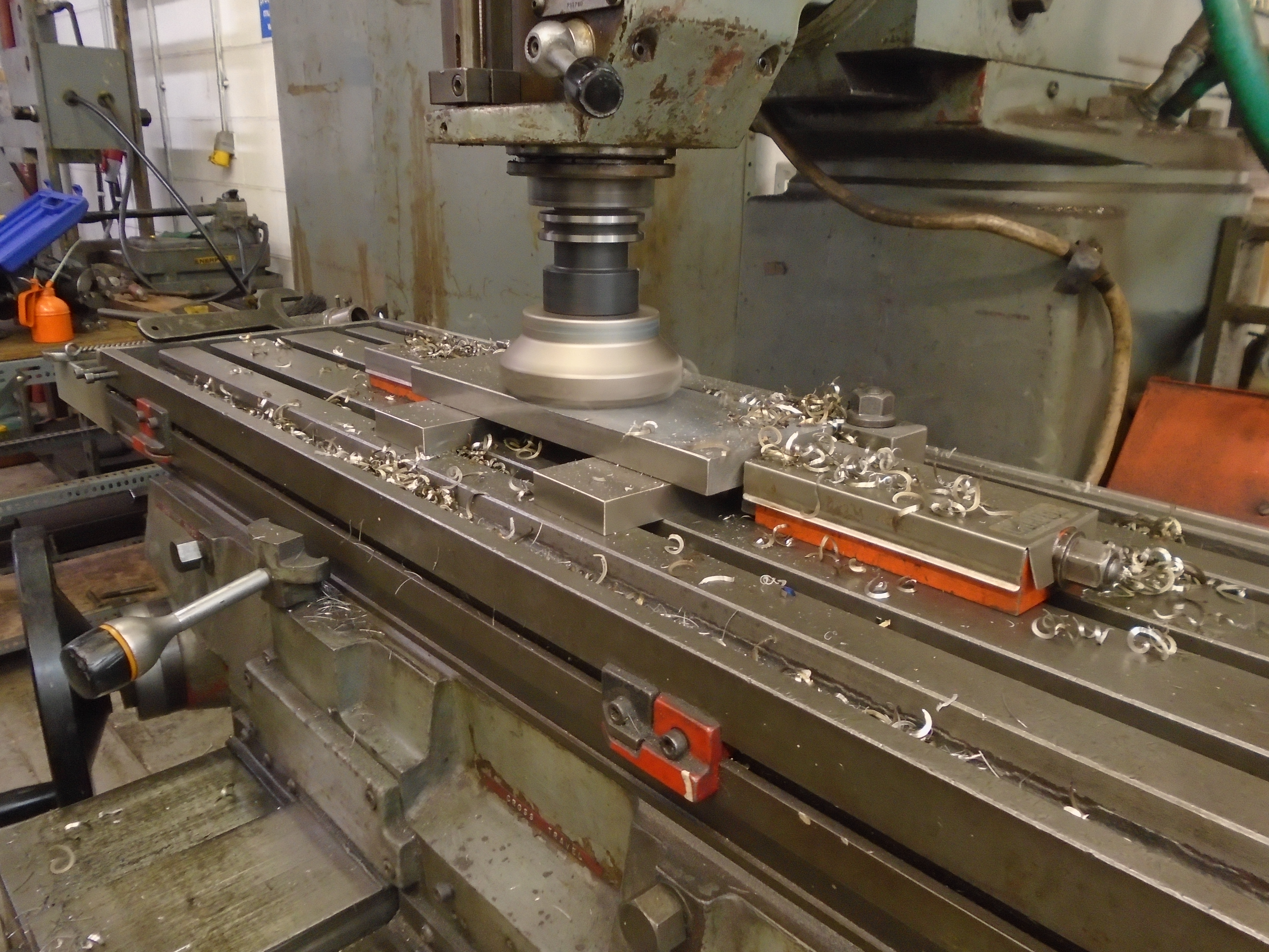
Below: Machining commences, using a set up with clamps which permit the material to be held on parallels direct onto the table of the milling machine, leaving the entire top surface available to machine as seen here.
Another detail post like this will appear at some stage, which will pick up where this one has left off, and cover the work to the axleboxes themselves and the horn faces which locate them in the truck frames.


Hello Mr Ellis, your article is fascinating regarding your discoveries with Gateshead 10’s trucks. I was informed by the late Merlyn Bacon (The TMS’s first volunteer Manager) that 10’s trucks were the last pair overhauled at York. He also told me the trucks were the only pair that received a full set of BR solid wheel centres. All other Gateshead cars retained some of the two varieties of original Gateshead spoked wheels centres. G/head 5 however has solid pony wheels matched to spoked driving wheels I recollect.I have no knowledge concerning any re-engineering of any new BR axles on the Gateshead cars however. Reverting back to G/head 10, Merlyn also told me its journey along with G&I 14 from Pyewipe to Clay Cross was on the main rail network! I hate to think of the condition of the thrust bearings following such a suggested journey! May I wish you success with all the work you are undertaking, and look forward to studying your final brake chain “set-up” linking wheel and track brakes!
Hi John – many thanks for the comment and observations – I’ll make sure Matt sees these.
That journey over BR must have been remarkable, and very slow!
Best wishes
Paul
Hi
What a major job, do thank the staff with all aspects of the job.
Was any preference to using shrink on or Loctite given and is there a stress because of the weld run due to any flexing.
Curious to know.
In service was the ride of the bogie a lurching ride and did it tear the bearings or just wear them
Going pre Beamish was the trackway different in make up to the current circuit.
All the best .
Hi David
There will be a further post later in the year regarding Gateshead 10 and the mechanical work carried out. There are a number of jobs still to tackle with the new journals and their interface with the axleboxes, as well as extensive preparation of new horn faces and guides. The team are also going to tackle a number of other jobs on the bogie frames, all of which will be documented by Matt in due course. The welding proposed is minimal, to avoid imparting any stress. The wear was caused by running contact, with 10 riding generally very well (far better than it’s mechanical state would suggest).
Gateshead used traditional grooved tramway track, whilst on the G&I, it ran on reserved track (with the short exceptions of the terminus approach at Corporation Bridge in Grimsby). This mixture is akin to that found at Beamish, though I have read that BR did re-profile the tramway wheels for use on the G&IER.
Paul