
Gateshead 10 Engineering Update Part 2…
In this post we hand over to Matt Ellis, Keeper of Transport, for an update on Gateshead 10’s mechanical overhaul…
As promised, here is an engineering update on the comprehensive overhaul of Gateshead 10. The last update generated considerable interest and some queries. Here I will try to answer some of the queries, as well as providing an update to the current status.
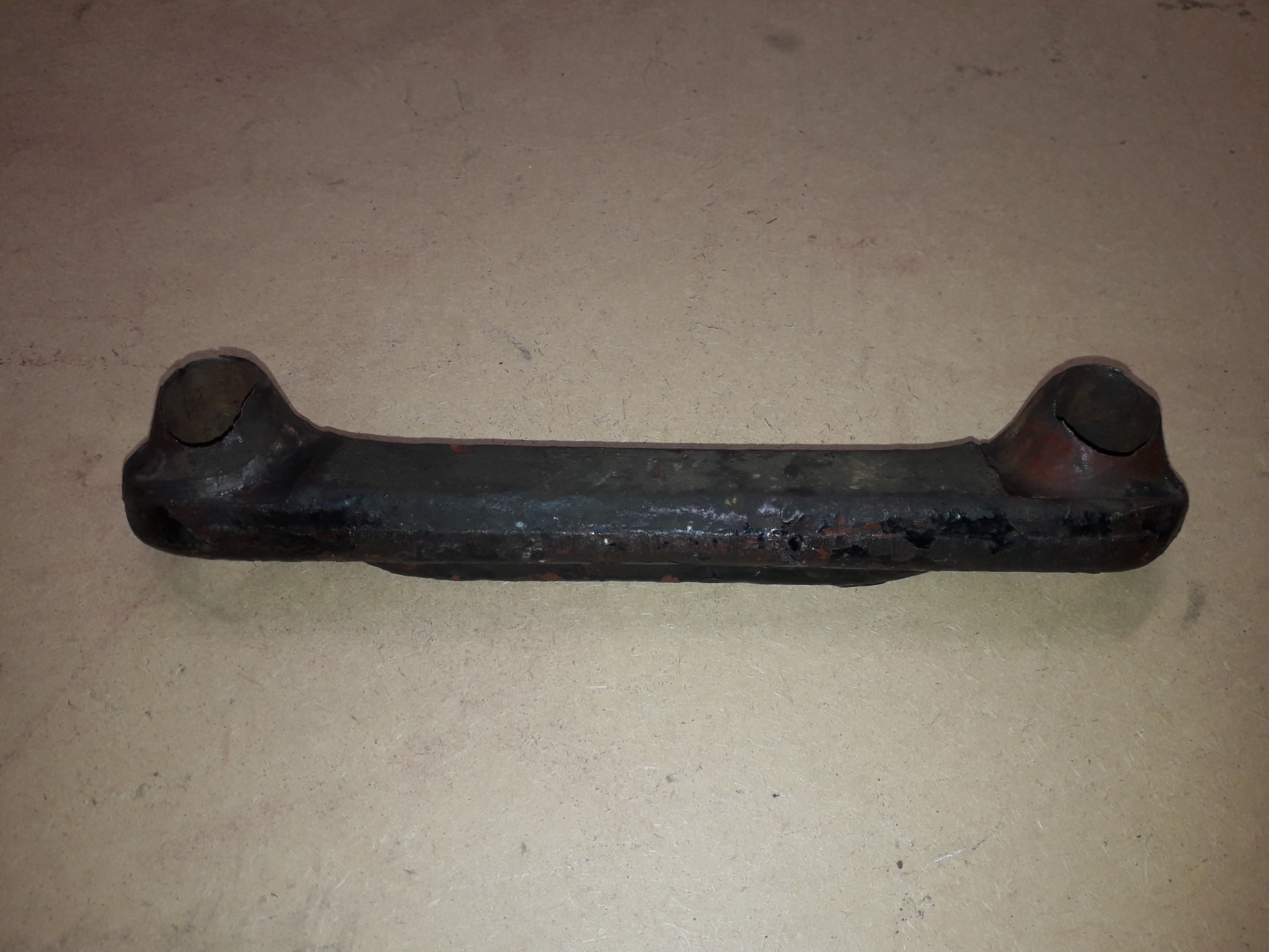
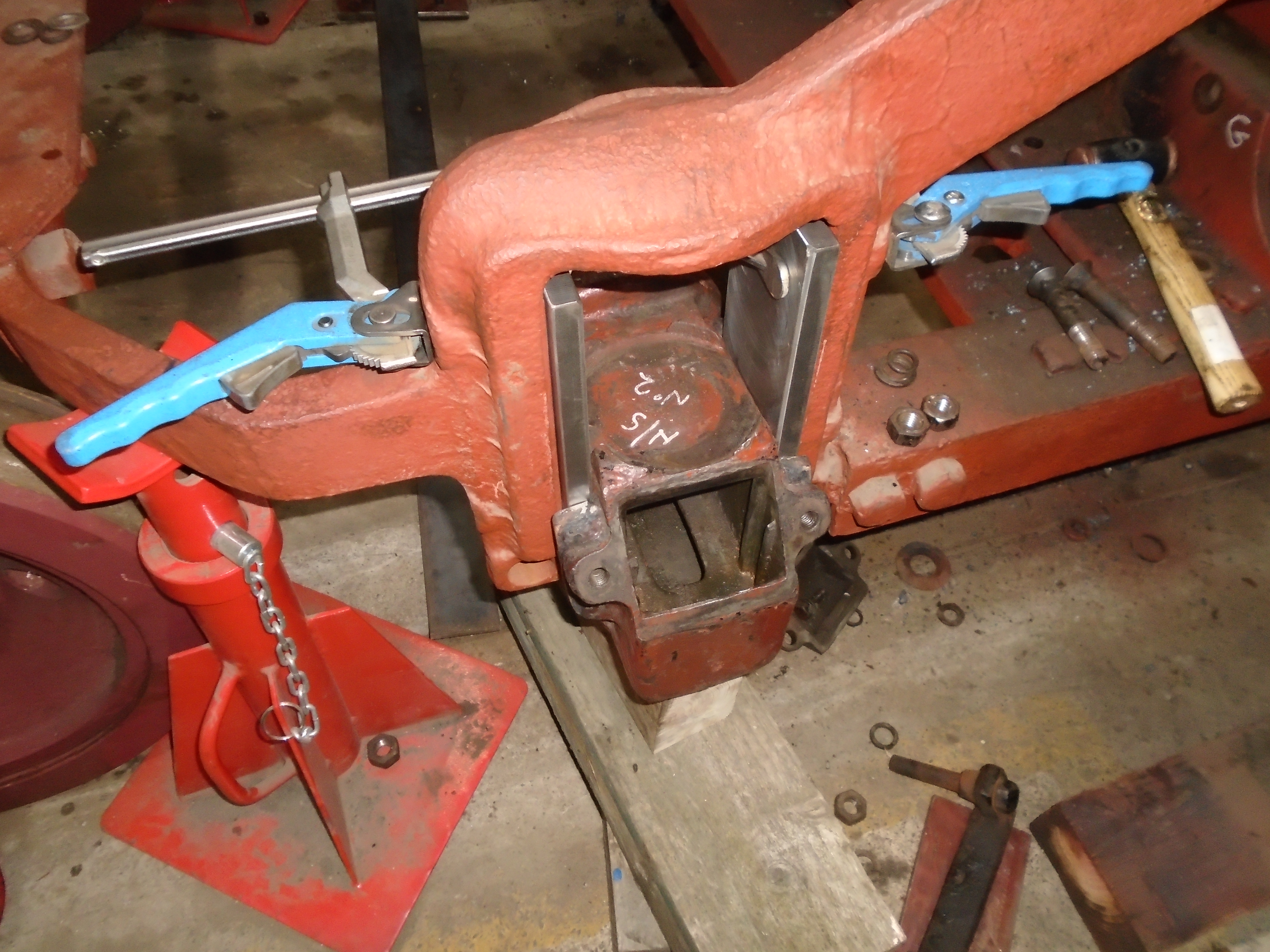
Below: We start with the horn stays. These fit to the bottom of the trucks after the wheelsets and axleboxes have been fitted. Their purpose is twofold. Firstly, they ensure that the bottom of the truck frame is held the correct distance apart around the horn gap (where the axle boxes slide up and down). If they were not there, then the bogie frame is likely to flex causing the horn gap to open and close, and potentially causing cracking at the top of the horns. Their secondary function, is to retain the axle boxes and therefore wheelset if for any reason the truck is lifted in its entirety or in a derailment situation.
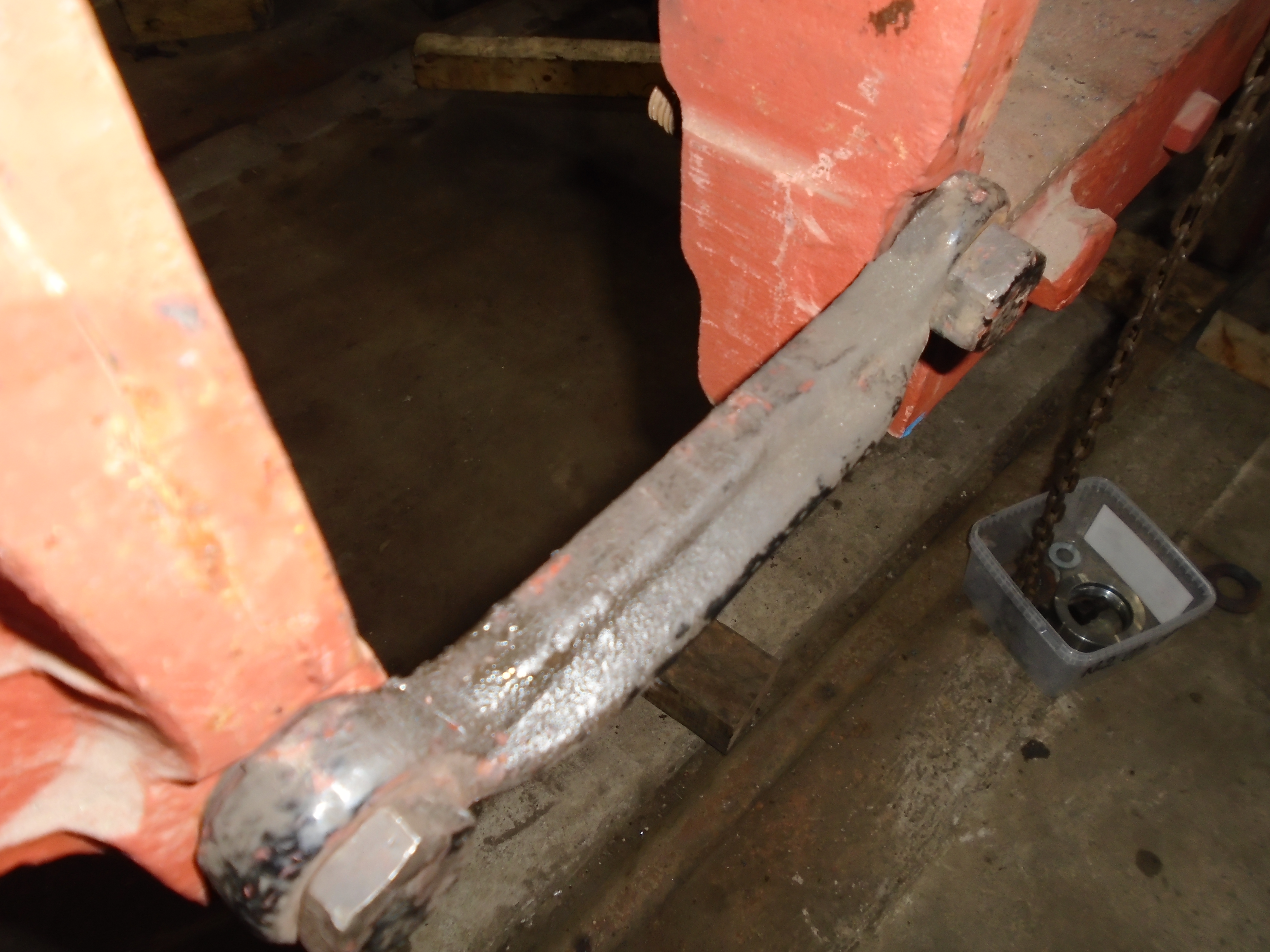
The horn stays on these trucks should tighten up onto a tapered seat at each end. This ensures that the horn stay itself cannot move against the frame and that it does not rely on bolts in holes for alignment, this in turn results in the distance between the holes in the truck frame being maintained and therefore the horn gap not flexing in service. Unfortunately not all is as it should be here. The main strap of the horn stay can be seen to be tight against the truck frame rather than on the taper.
Below: In this photo, the strap is again tight against the frame but the taper is nowhere near tightening into its seat.
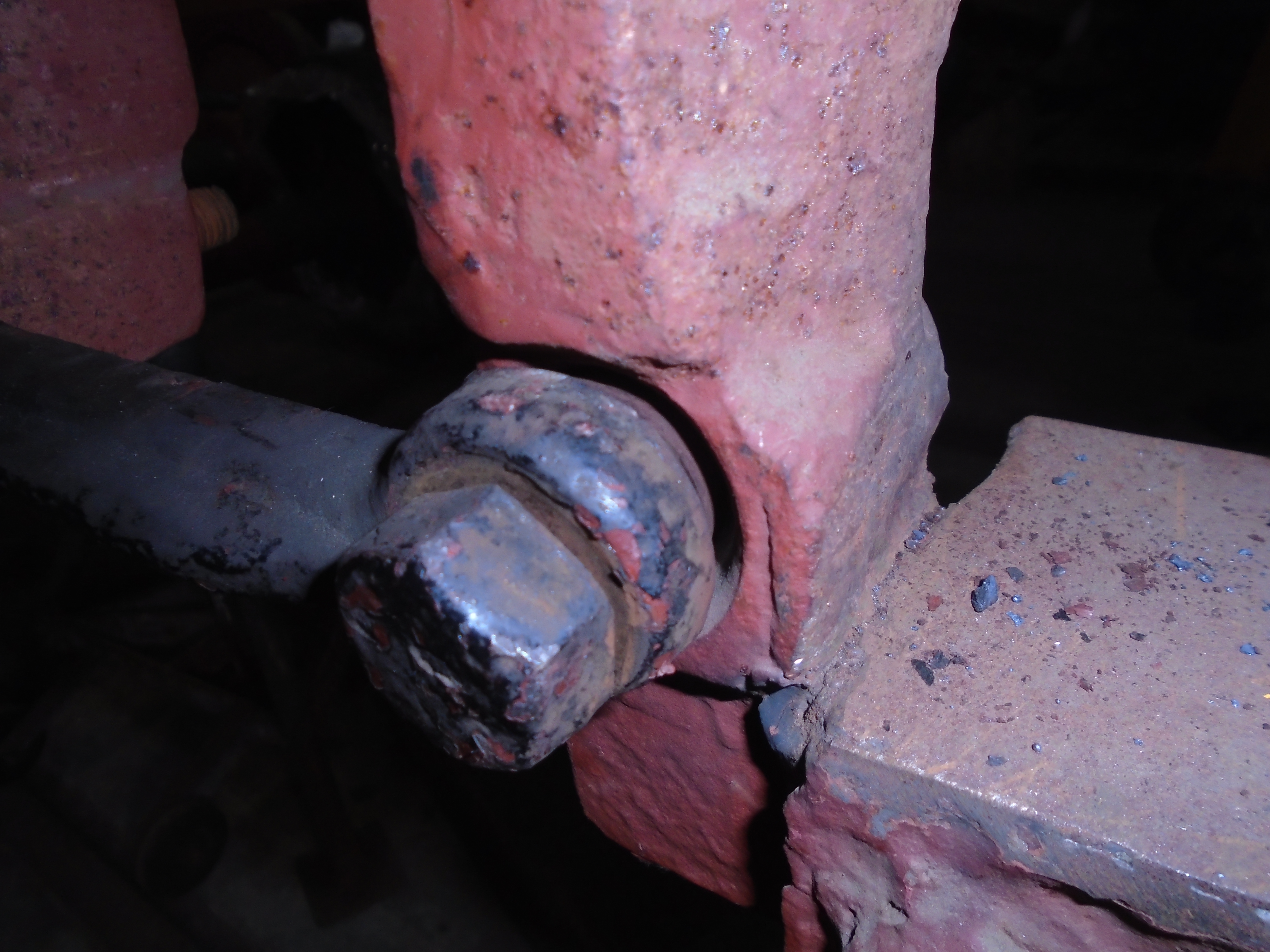
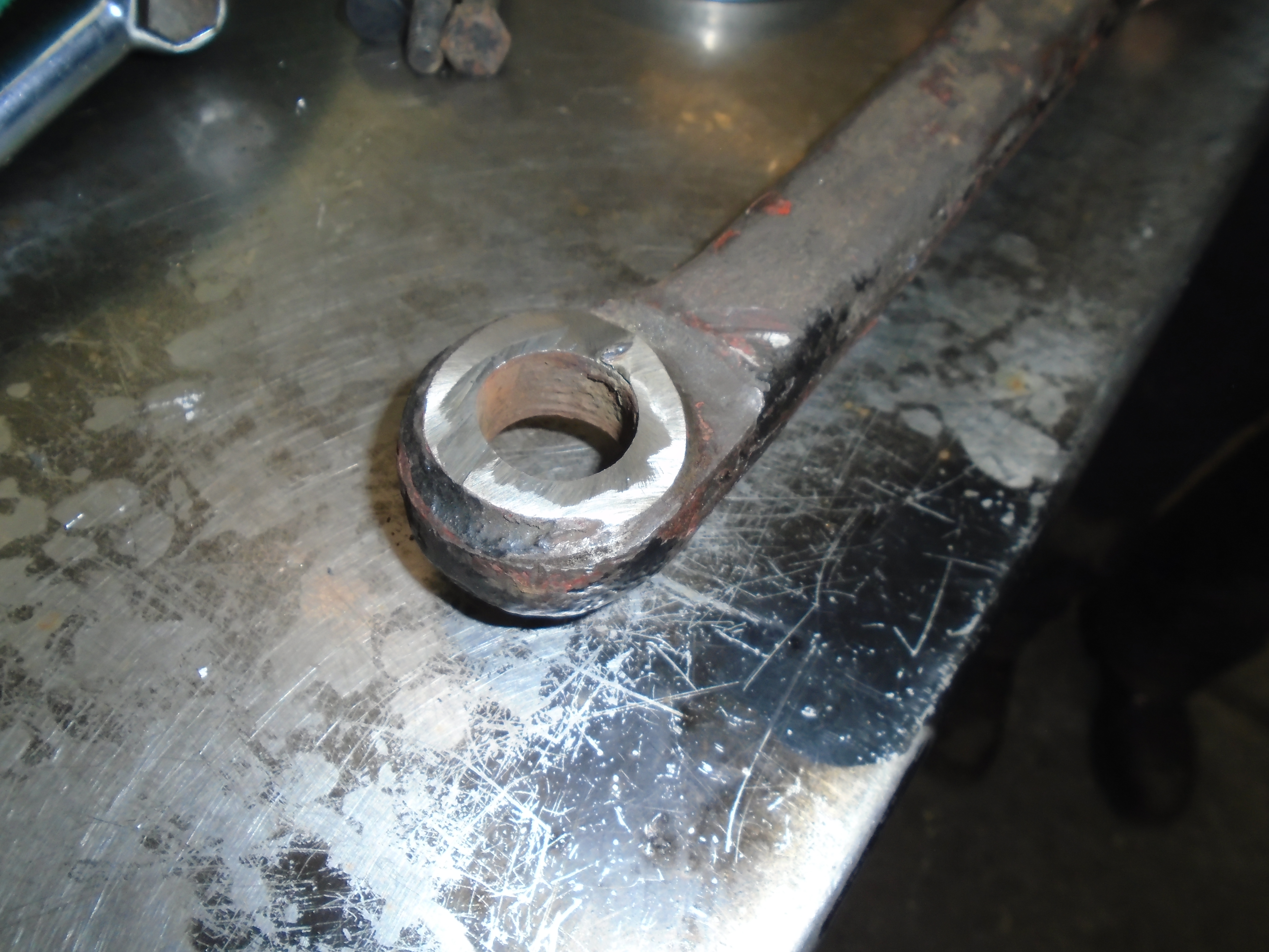
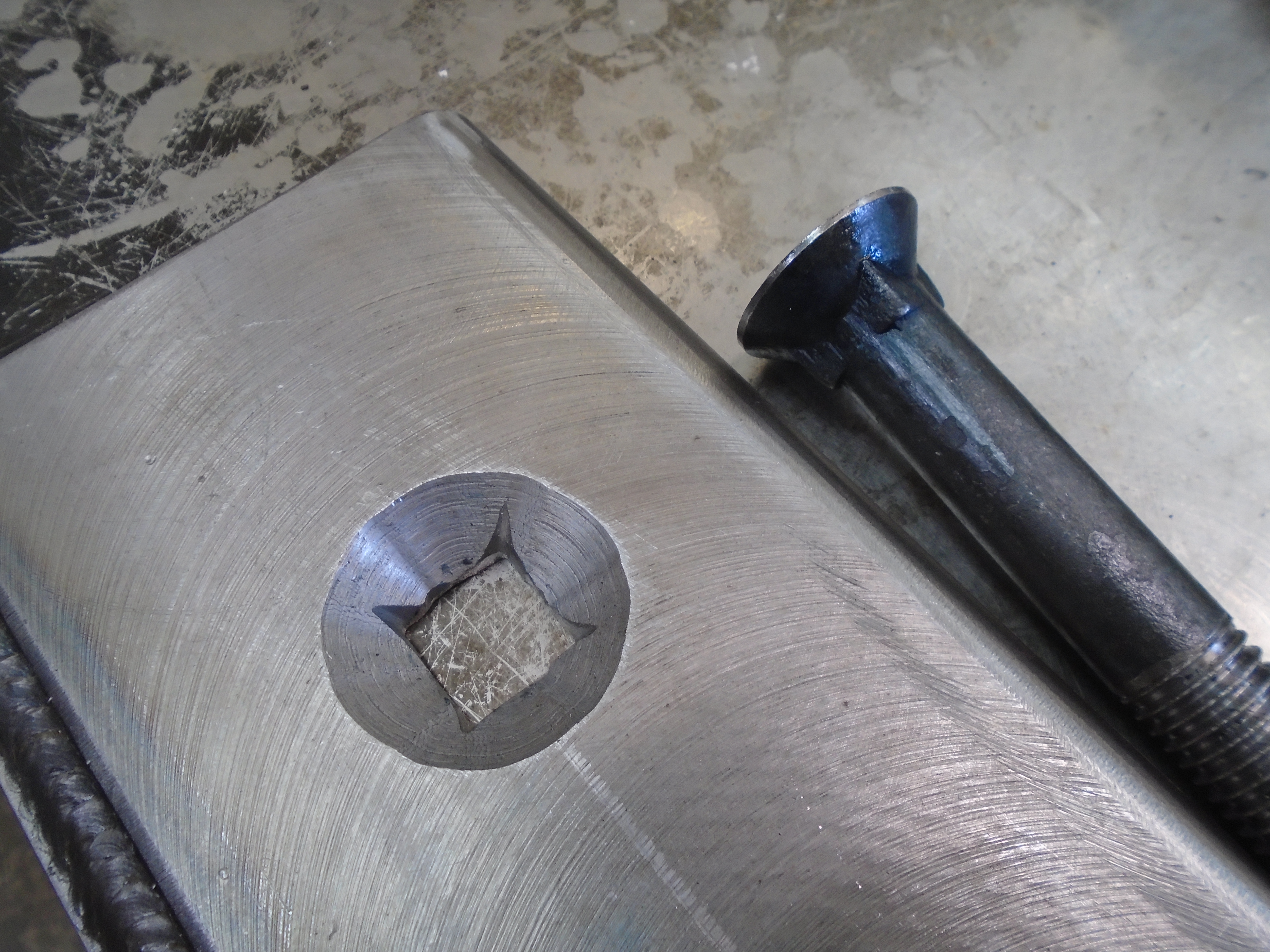
Below: In the next two photos, the wear to the horn stay is evident. Really these should not be wearing components as they should not move in service, but a hard life has clearly been had. The taper itself is well worn, with the taper no longer seating in the holes, the bolts have tried to maintain alignment, resulting in the worn the holes (and bolts!).

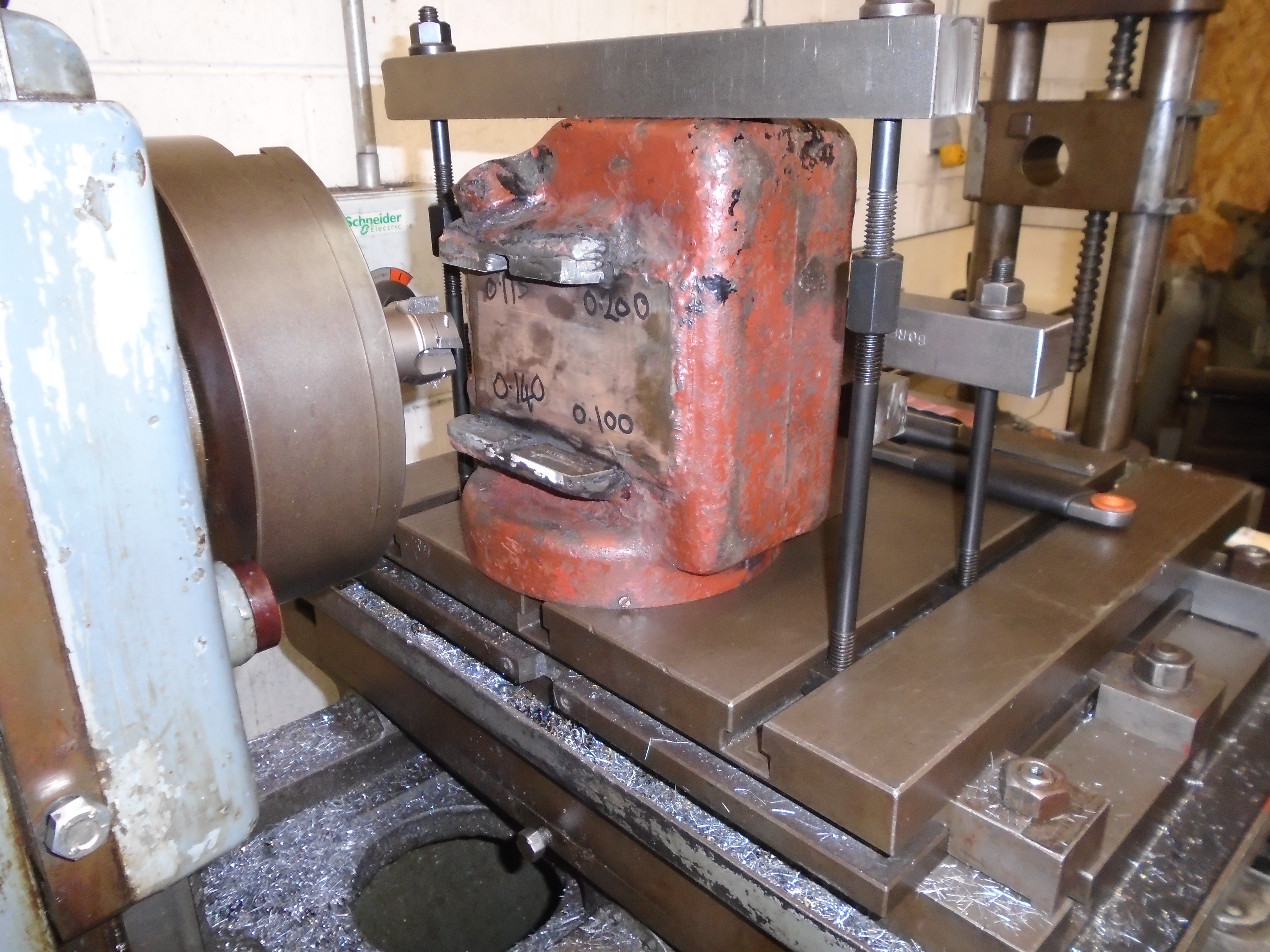
Below: A plan for repair was discussed, so first the worn tapers were ground flush with the strap
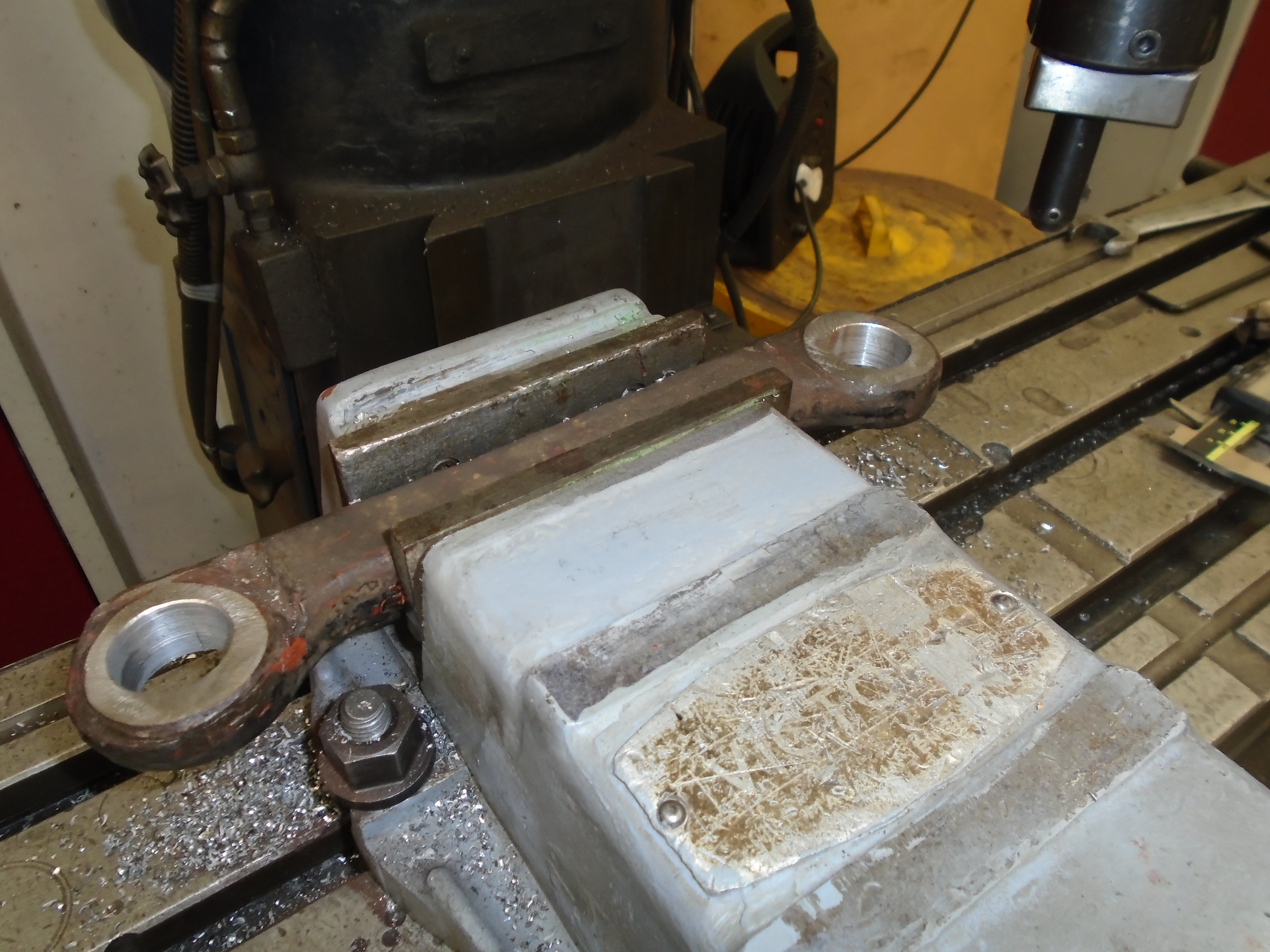
Below: The holes were then bored out until they cleaned up, but at the correct hole centres for those in the trucks. In total there are eight of these components – easier written than done!
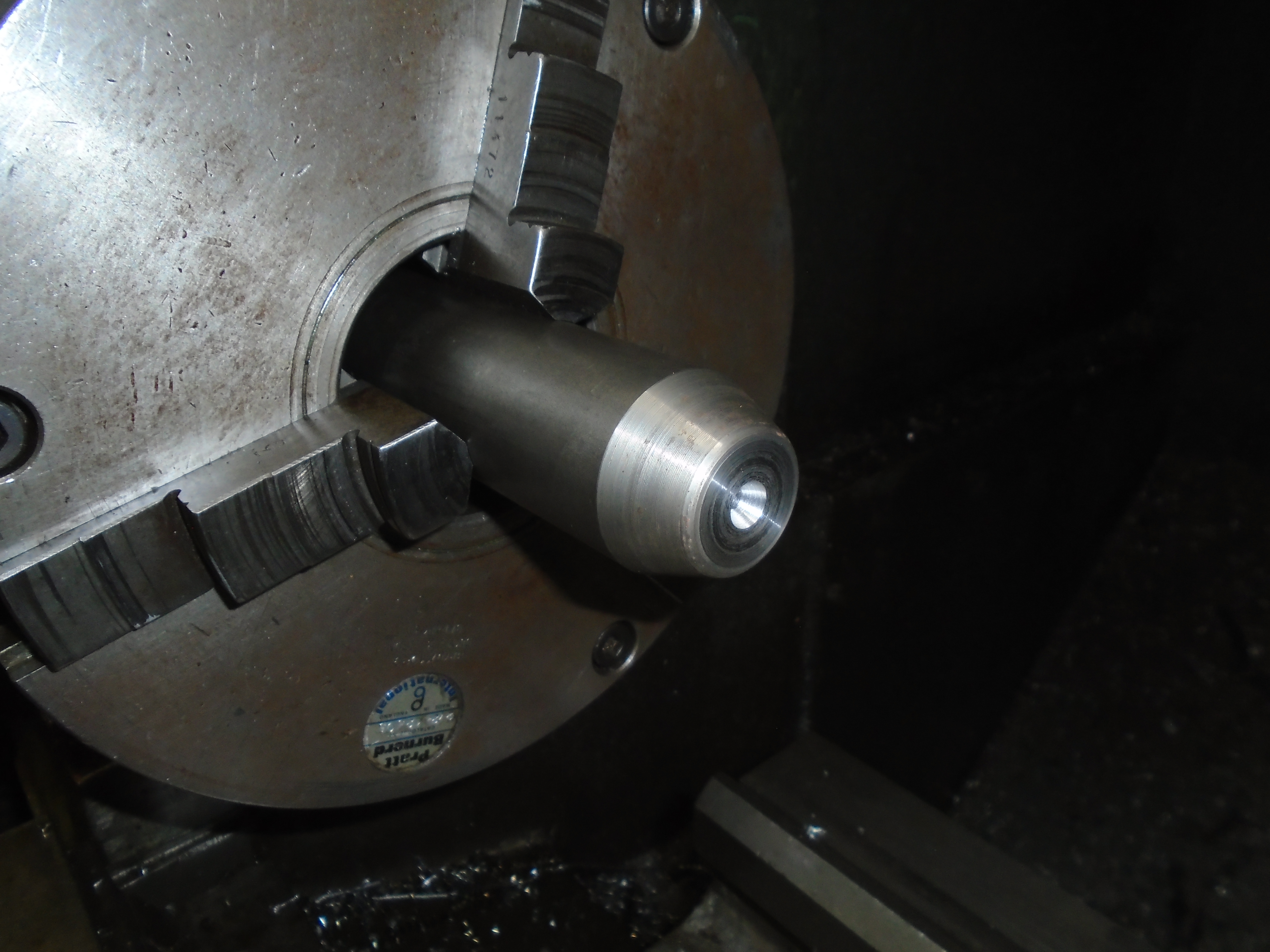
Below: New tapers were then turned, the rear of these having a register to press into the bored holes.
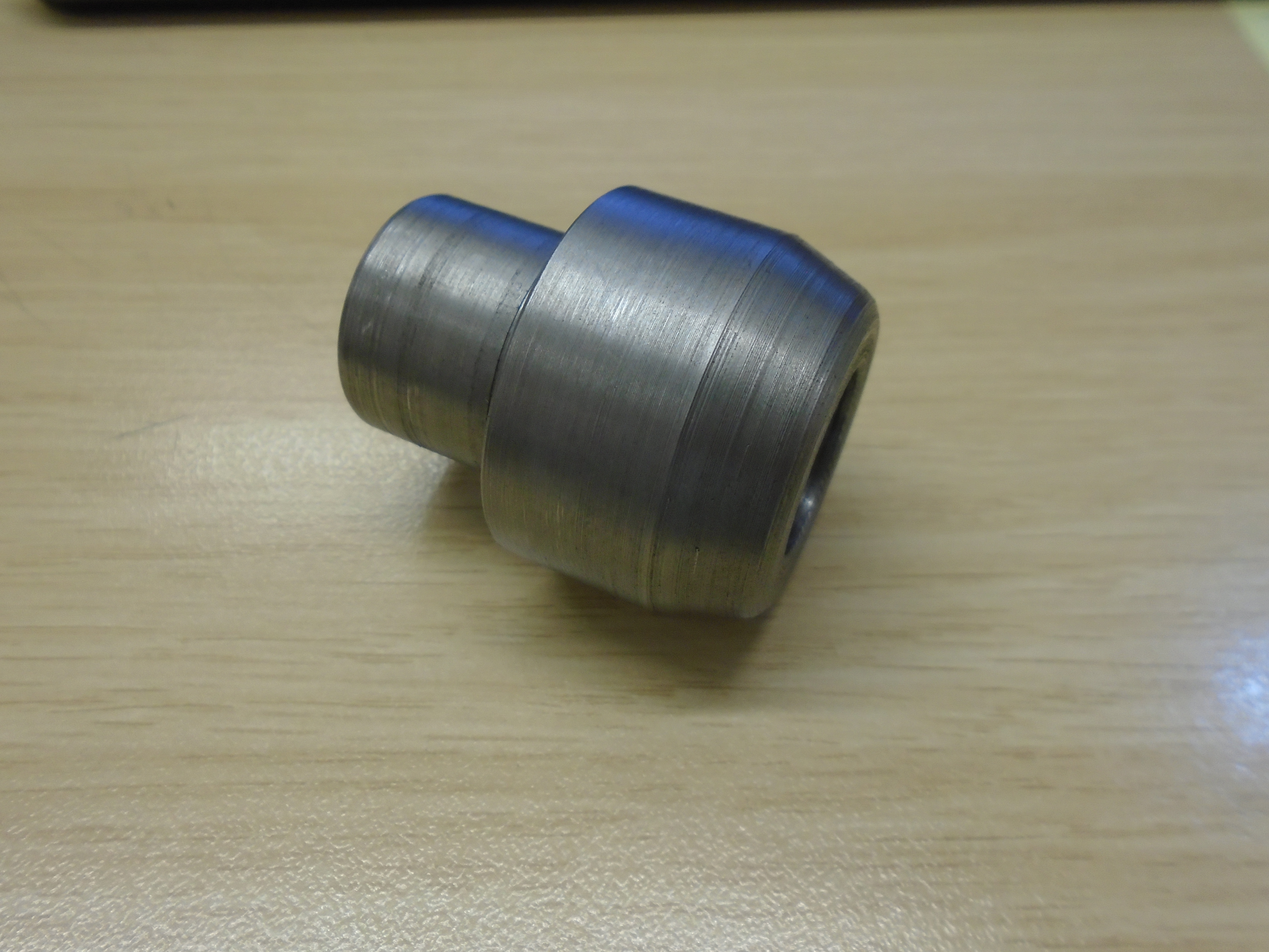
Below: The new tapers are then pressed into the horn stay, and will have a weld run around to retain them. The horn stays should then be fit for many years to come. This repair is a good example of where the cost, time, outcome and curatorial considerations have to be thought through. We considered making new horn stays, which would have probably failed on all these considerations except the final outcome (the originals are forged). The repair we have completed ensures a relatively cost effective process, it has not taken a significant amount of time in comparison to getting new forgings made, they will work as well as a new one, and we’ve managed to keep most of the original component for further service. If only we could achieve that with every component or project!

Picking up from the previous post now, the modifications to the axle ends were covered. I wanted to include some drawings and sketches to show the complete assembly of wheelset in truck, both prior to repair/modification and the proposed result. At the time I was waiting for the licence for our drawing software to be renewed. This has now been completed which has enabled me to draw up a mock assembly showing what we started with and what we will end up with. These are really just thorough sketches which show the issues and principles of the modifications, rather than perfectly dimensioned drawings of exactly what is there. It would take much longer to produce such drawings, for little additional benefit.
The sketches are not just for the benefit of blog readers. We have an Engineering Change Management (ECM) process, which we apply to all rail vehicles as required (and defined) by our Safety Management System, whenever a substantial change is made to its construction. The idea of the ECM process is to fulfil two objectives, firstly to document the change in a way that shows why the changes were made, and the rationale, which also provides a historical record for future generations. The second objective of the ECM process is to assess the risks brought about by the change, and explain the mitigations taken in support of them. For example a weld and surrounding area may be non-destructively tested to prove that the weld repair has not caused the weld or the parent metals to crack, providing some mitigation against complete failure in service due to a small crack immediately post-repair. As you can imagine, the ECM document covering Gateshead 10’s overhaul is going to be substantial.
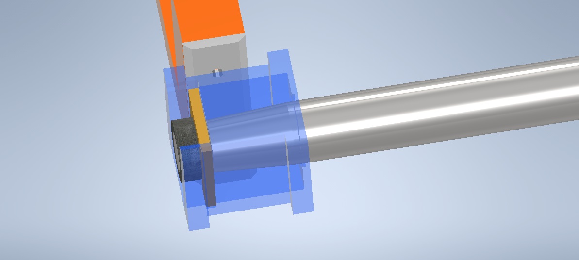
Below: Assembly Pre Modifications – Here is a section of the sketch. The bogie frame is shown in orange, and the axle (without wheels) in polished steel. The axlebox is shown in clear blue, which enables us to see the tapered axle journal, with the thrust bearing (in brass) and collar (black) on the axle end. The old horn faces are shown in steel, bolted to the truck frame. As can be seen, the length of the axle between the two collars has the effect of pulling the axleboxes in, right up against the side of the horn face. In a couple of cases, this had caused wear to the truck frame itself. The horn faces also had excessive chamfers on them as shown, which presented quite a narrow edge to the axlebox for the thrust face. Also visible is the sizeable gap on the inside of the truck frame, to the axlebox. As designed, there should be no gap, with the axlebox centred about the frame, with horn faces that wrap around the sides of the frame.
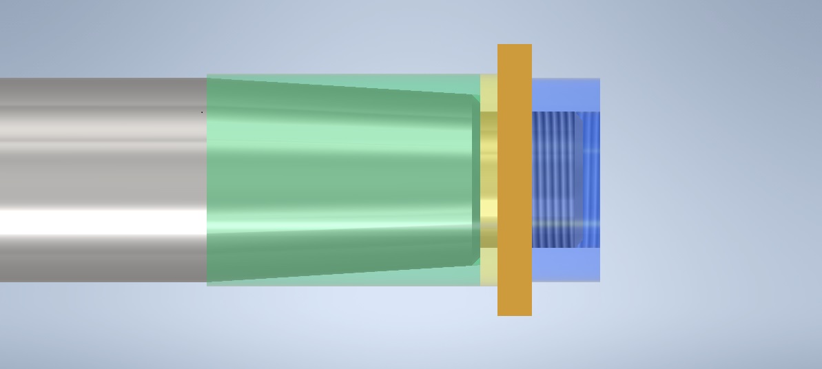
Below: Axle Assembly Post-modifications – This sketch shows what the axle ends will look like upon completion. The axle is shown in steel. Then left to right we have, the axle sleeve (green) which brings us back to parallel journals. Then there is the thrust collar (yellow) which effectively lengthens the axle, and provides a good continuous face to act on the thrust bearing (brass). Finally, the collar (blue) is fitted to the end of the axle, giving the correct groove for the thrust bearing. Through the blue collar, can be seen the end of the axle, showing the effective lengthening of the axles achieved. Both the green sleeve, and blue collar have retaining welds (in the prep vee’s shown).
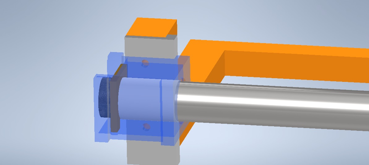
Below: Assembly Post Modifications – Here is what we hope to end up with. The axle can now be seen in steel, with the sleeve and collars fitted and the thrust bearing in place. In relation to the frames, this has moved the axleboxes out giving clearance on the outside of the truck frame. New horn faces are then made, shown in steel here, which wrap around the inside of the frames, providing a full face to bear against the axleboxes for thrust loads. There is only so far we can go with increasing the effective length of the axles before we end up in thin air. So wrapping the horn faces around the inside of the frame only is a bit of a compromise, as we can’t go long enough on the axle to provide sufficient room for a wrap around on the outside of the frame too (or at least not one that would be of useful thickness).
These last few paragraphs explain the situation for the driving axles, which were the worst. The pony wheelsets have had largely similar work done to them. The main difference, and that which you will see in photos is that the pony wheelsets do not get the wrap around horn faces. This is because the thickness of the horn faces themselves on the pony wheelsets is such that they cover almost the entire thrust face anyway, so there would be very little to be gained by making these wrap around the frame.
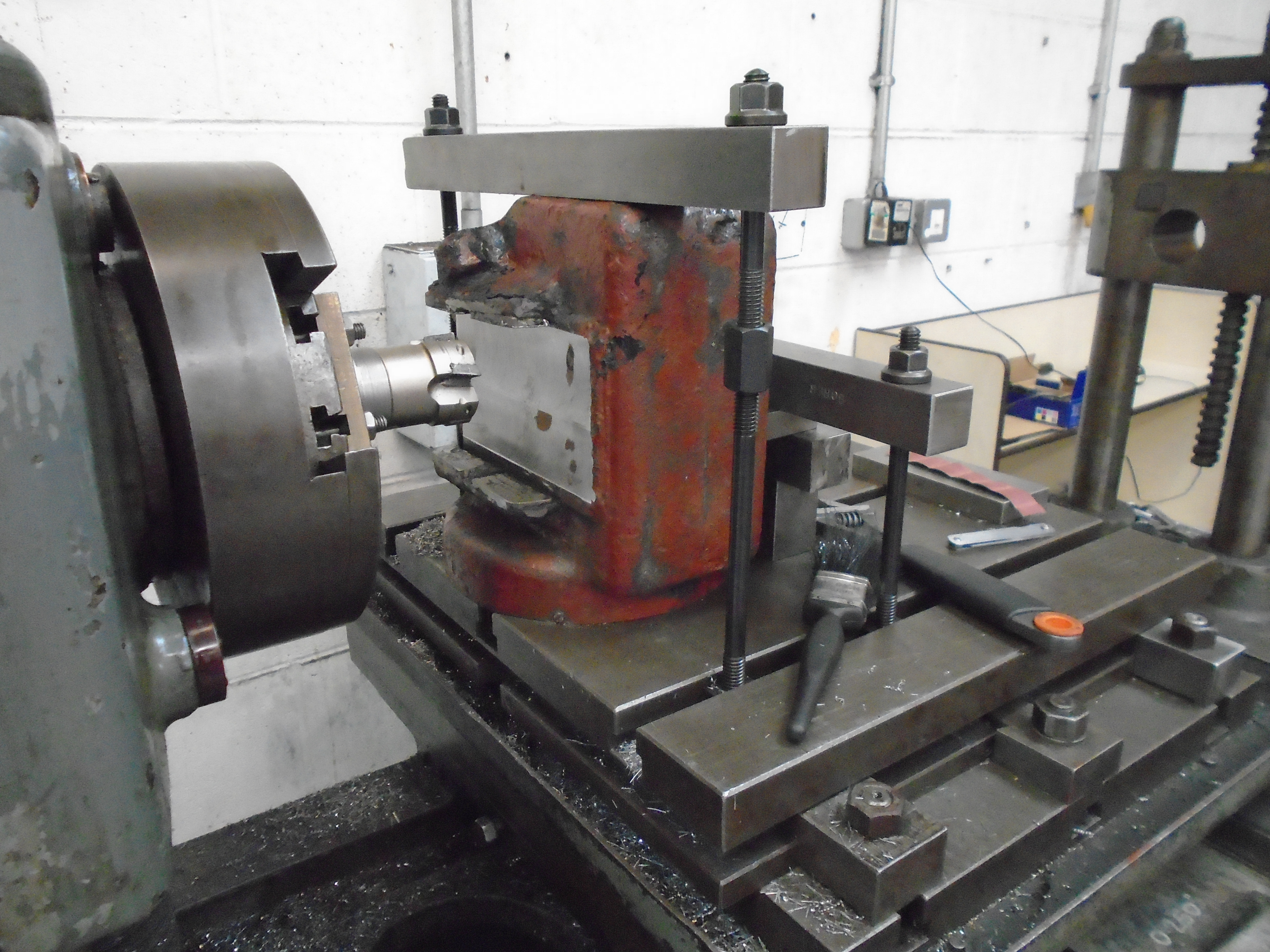
Below: In some of the news posts earlier in the year, Zoe was seen making tooling for the borer to enable machining of the pony wheelset axleboxes. Each axlebox has had the thrust edges built up and then set up like this.
Below: Each horn face on the axleboxes was then skimmed and the thrust edges machined to dimension. Seen here part way through machining.
Below: Each axlebox (pony and drivers) is then fitted into the truck, with the horn faces to check the fit after the horns are machined to thickness. Having achieved this for both ends of a wheelset, they are then fitted to the frame with the wheelset, and locations for the holes in the horn faces marked through from the truck frames.
Below: An additional step for the driving axlebox horn faces is the welding on of the wrap round portion, which can be seen here.

Below: With the holes marked through, they are opened out to full size, then countersunk, then filed out square to take the countersunk square bolts.
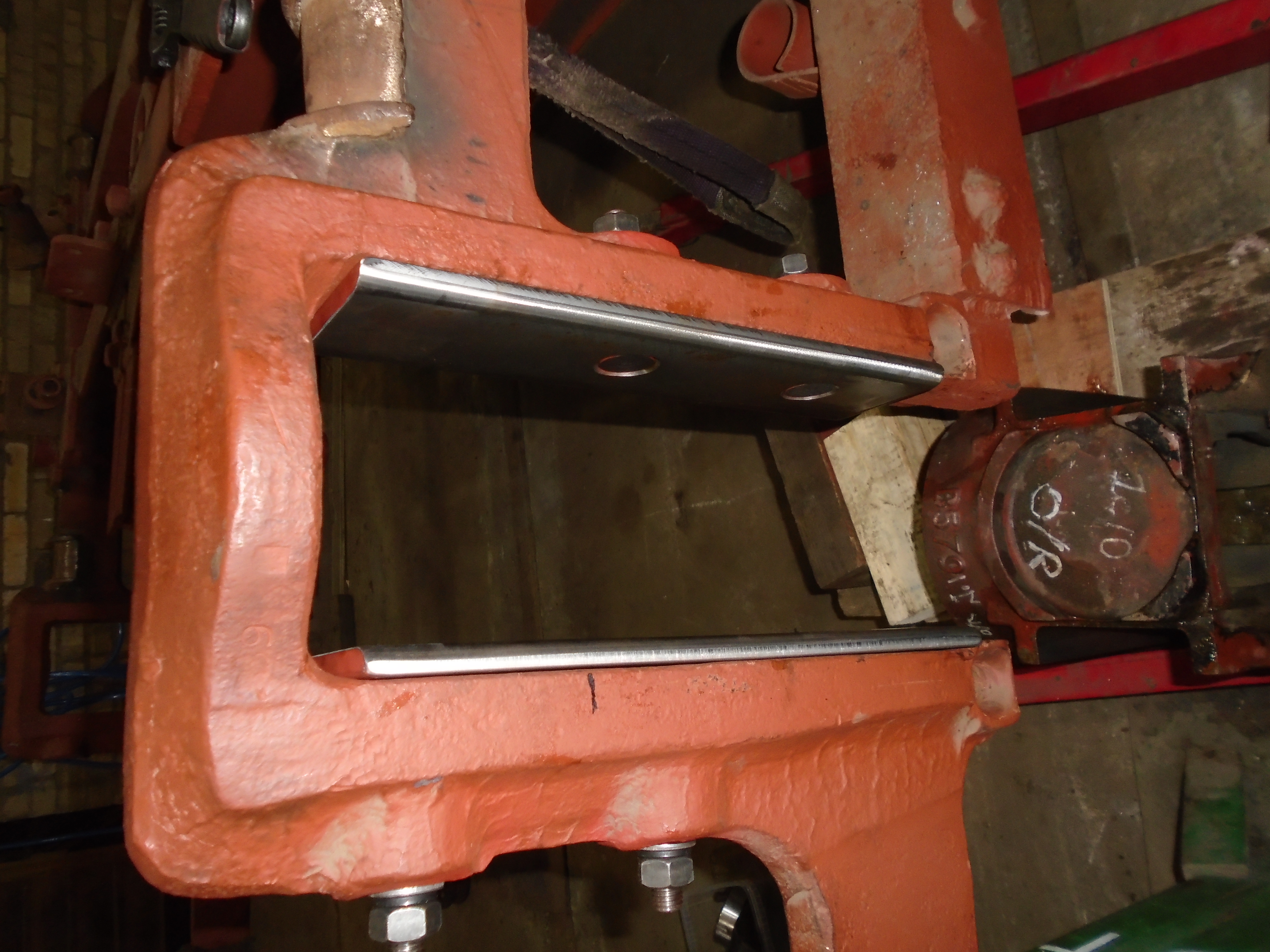
Below: This is a significant photo. With the backs of the horn faces painted, these two are now fitted. These two were the first components to be fitted which will not need dismantling again during the course of the overhaul. A small step, but it’s a corner turned.
I’ll leave this post here for now. The aim is to have the trucks wheeled, with completed axles, horn faces and horn stays by Christmas. The wheelsets will need to go in and out a few times after that for other reasons but the work on them will be complete.


I was a little concerned that ground off metal from the links and the welded on replacements were a risk taking into account the welding could nor achieve an all face welding and as a forged item would be a different material by nature to the new metal. producing a area of stress. Are these heat treated or shot blasted areas.
The sliding faces were under a large area of surface contact and trued but the repaired links relatively fragile proportion for the strain they are to take. Are you able to support and keep true the bogie and still allow flex without cracking. Looking back at the history a challenge for the best