
Head Wrightson Coffee Pot No.1 at 150 years old Part 2…
Coffee Pot – Restoration to working order, 2008 – 2010
Welcome to Part 2 of this three-part history of Head Wrightson Coffee Pot No.1, which is celebrating its 150th birthday in 2021. In this post I will describe the restoration that commenced in 2006 and was completed in early 2010 and which included the construction of a new boiler to the original pattern and restoration of some other features to back-date the locomotive to it’s 1871-73 appearance.
When I started at Beamish in 2004, I was keen to look at the possibility of restoring the Colliery railway sidings to operation. We had, at the time, Black Hawthorn 0-4-0ST Wellington on site, but this was dismantled and had managed relatively few steamings in the early 2000s. In addition, Coffee Pot was laid up and the dismantled remains of No.18 (the former Seaham Harbour 0-4-0ST built by Stephen Lewin in 1877) were also on display, with a more or less overhauled boiler for it sat outside. The saga of No.18’s restoration is a separate tale but if you want to read an overview, take a look at the articles on this blog, under the heading ‘Articles’ above.
I really wanted to tackle No.18, and this formed the basis of a proposal for the whole of the railway in the Colliery area. However, it was clearly a bigger job and as I was inexperienced and new to the museum world (though I had previous experience in railway preservation), I thought a more fundable and contained project might be a better place to start. After much thought and discussion with colleagues in the sector, I decided that Coffee Pot had the better chance of both attracting funding and also of being completed in a reasonable timescale. It was known that the Achillies’ heel was the boiler, so it was decided early-on that a new boiler would form part of the restoration programme. As it was to be new, we could also back-date the locomotive to as-built (or nearly so) condition, therefore connecting it with the region more closely, as an example of a Teesside manufacturer, rather than the evolved machine used in a Surrey quarry. The replica cab fitted in during the 1980s was dismantled and placed into store at Beamish.
Conservation Management Plans
Keen to apply museum standards of collections care and thought to the project, a Conservation Management Plan (CMP) was compiled. Reapeating its own words, the introduction to this document read:
This document is the Conservation Management Plan (CMP) for the Head Wrightson ‘Coffee Pot’ steam locomotive No. 1 of 1871. It has been prepared by Paul Jarman, the Transport Curator at Beamish, The North of England Open Air Museum, in County Durham. It is based upon a document produced by Dr David Gwyn (a sessional lecturer in Heritage Management at the University of Wales, Bangor) and Jim Rees, ([then] Rail Vehicles Collection Manager at the National Railway Museum, York) Lilla group who own a narrow gauge steam locomotive which once operated in the Welsh slate industry. As such this was the first time a plan of conservation and management had been written for a locomotive with the potential to be returned to working order.
Until September 2004 no CMP as such had been undertaken for an operational historic locomotive, or locomotive with the potential to be operational. It is the work referred to above which inspired the preparation of the CMP for Beamish’s Lewin steam locomotive in 2006 and this Coffee Pot document in 2007. There have been, however, several studies published regarding historic inactive locomotives which have considered options for conservation and interpretation by Dr Michael Bailey and Dr John Glitheroe, most notably the study of Stephenson’s Rocket and more recently the Hetton Lyon locomotive. It is interesting to note that Lilla, for which this format of CMP was developed, visited Beamish in April 2016.
The CMP covered many areas, both recording Coffee Pot’s history as far as I could research it, and defining the form in which it would be restored, and how. This took into account items that would be replaced, renewed or conserved, providing a comprehensive supporting document for the locomotive and hopefully ensuring that what is known about it is both recorded and the rationale for any work carried out discussed for future generations of curatorial and engineering staff at Beamish. It is often the case that the curator involved in a project can write or speak extensively about the artefact and restoration process from memory, but this does not necessarily mean this is captured for a life beyond this memory!
In addition to the CMP, a restoration diary was kept and chronicled on the museum’s website. This was later copied over to the transport blog and the link below will take you to this synopsis. Searching ‘Coffee Pot’ in the search field will also bring up every other post where the locomotive is mentioned- of which there are quite a few now!
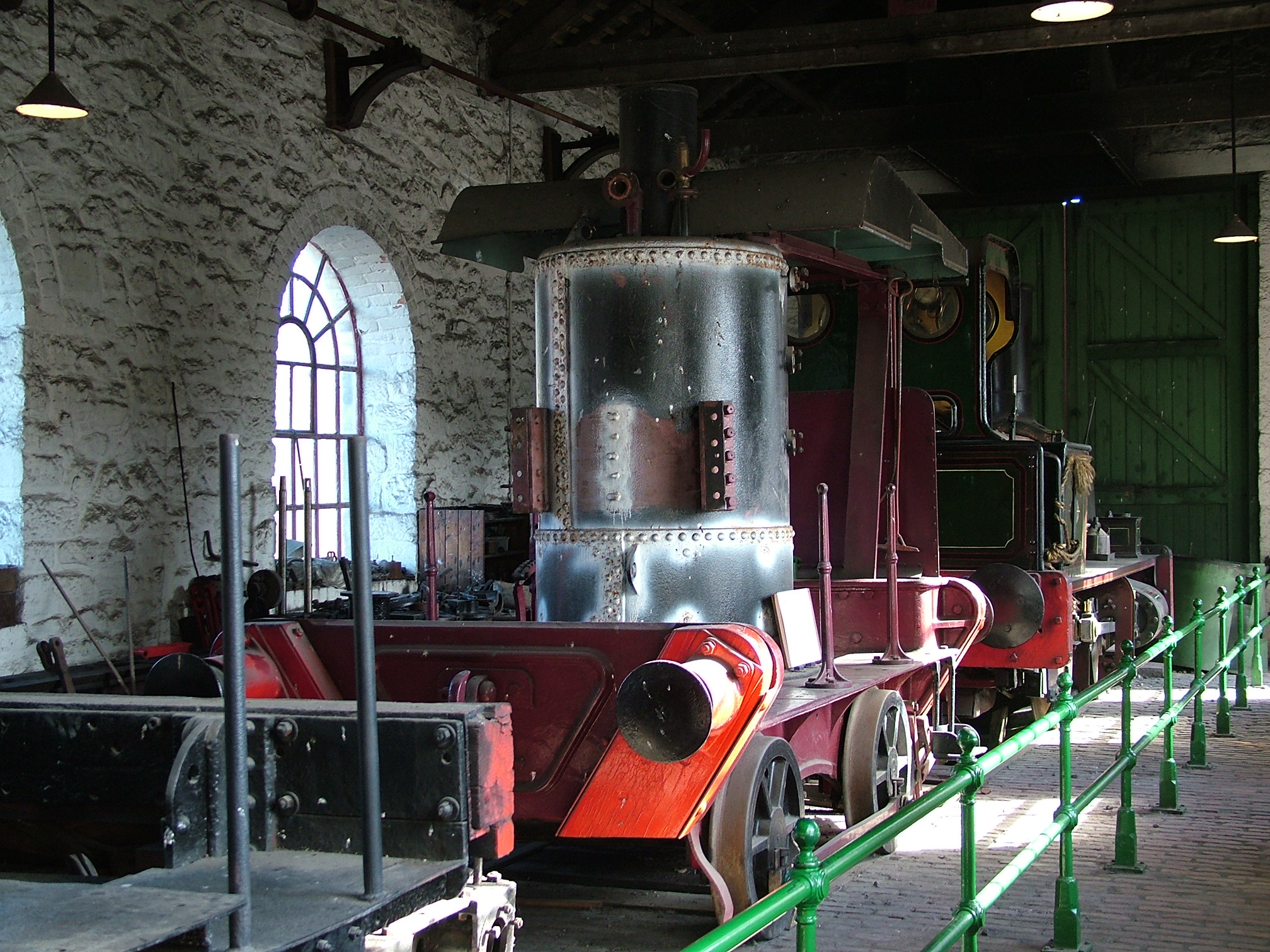
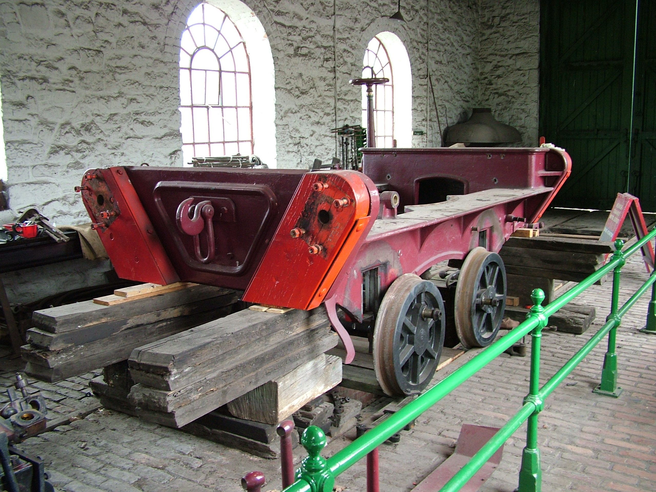
Below: This 2005 view shows the engine works in the Colliery, with Wellington by the doors, Coffee Pot in the middle and No.18 in the extreme foreground.
Below: A view of the footplate showing the white paint of the non destructive testing (NDT) process applied – in this case a Magnetic Particle Inspection (MPI). Note the cast footplate floor (a single and very heavy piece!) and the plate to the far side of it (there is one each side) behind which the leaf springs for the rear axle are positioned.
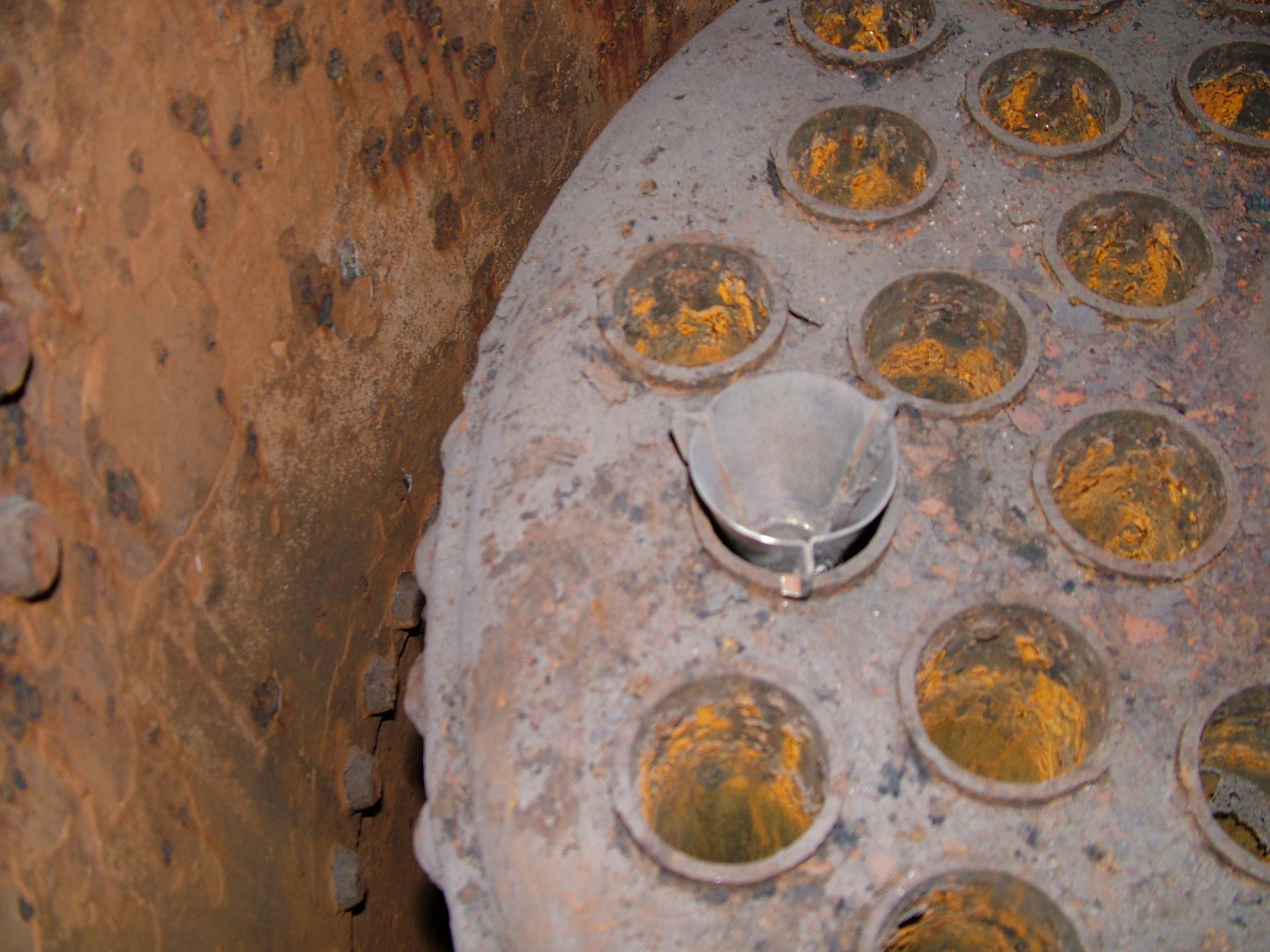
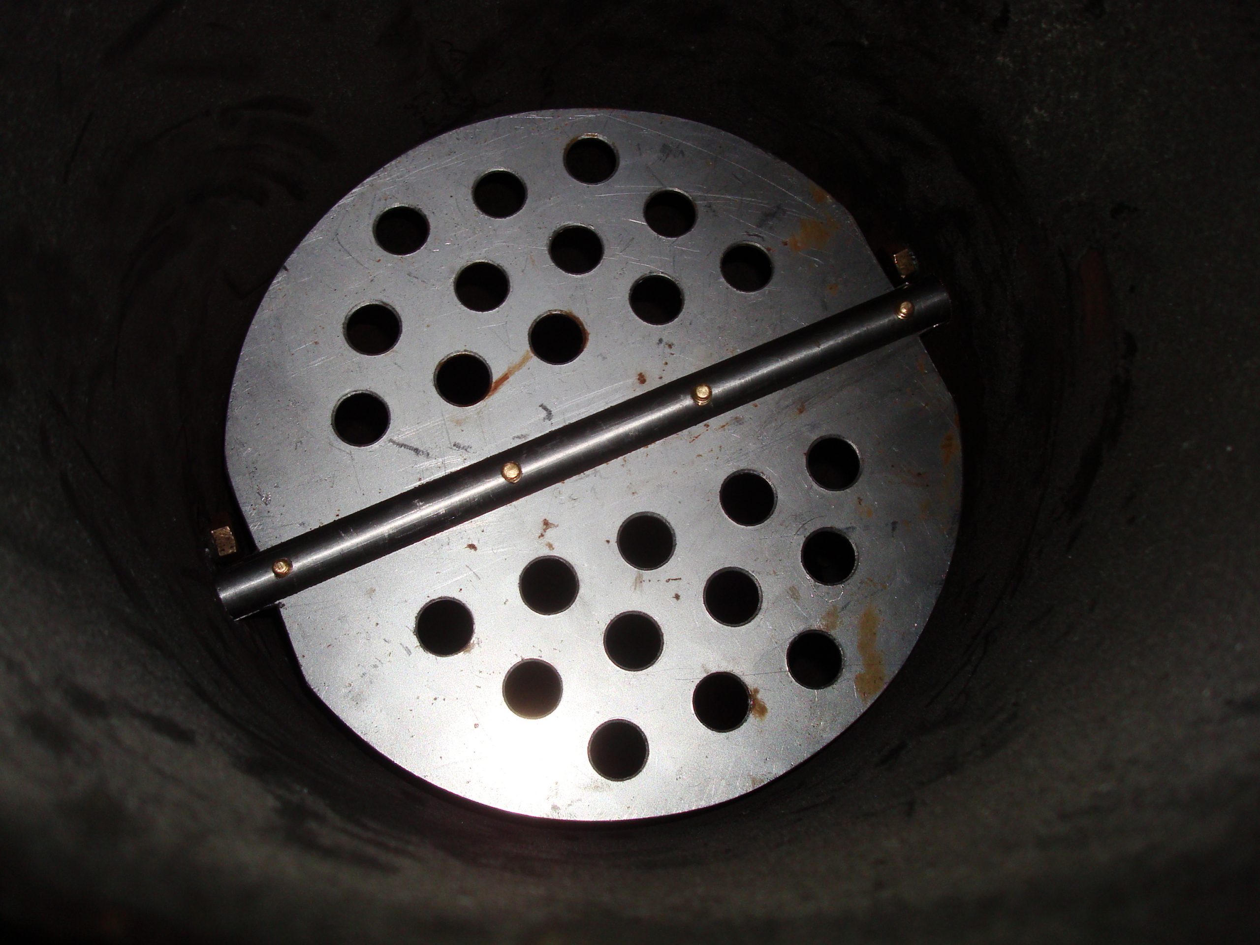
Below: Looking into the (fourth – see Part 1) boiler, via the large inspection door, to reveal the top of the firebox/furnace. The tubes visible are not smoketubes but hanging tubes; these project into the firespace and are blank at their far end. These have inserts (one example is seen temporarily fitted here) that encourage the water to circulate within this space (so we are looking into the waterspace of this type of boiler).
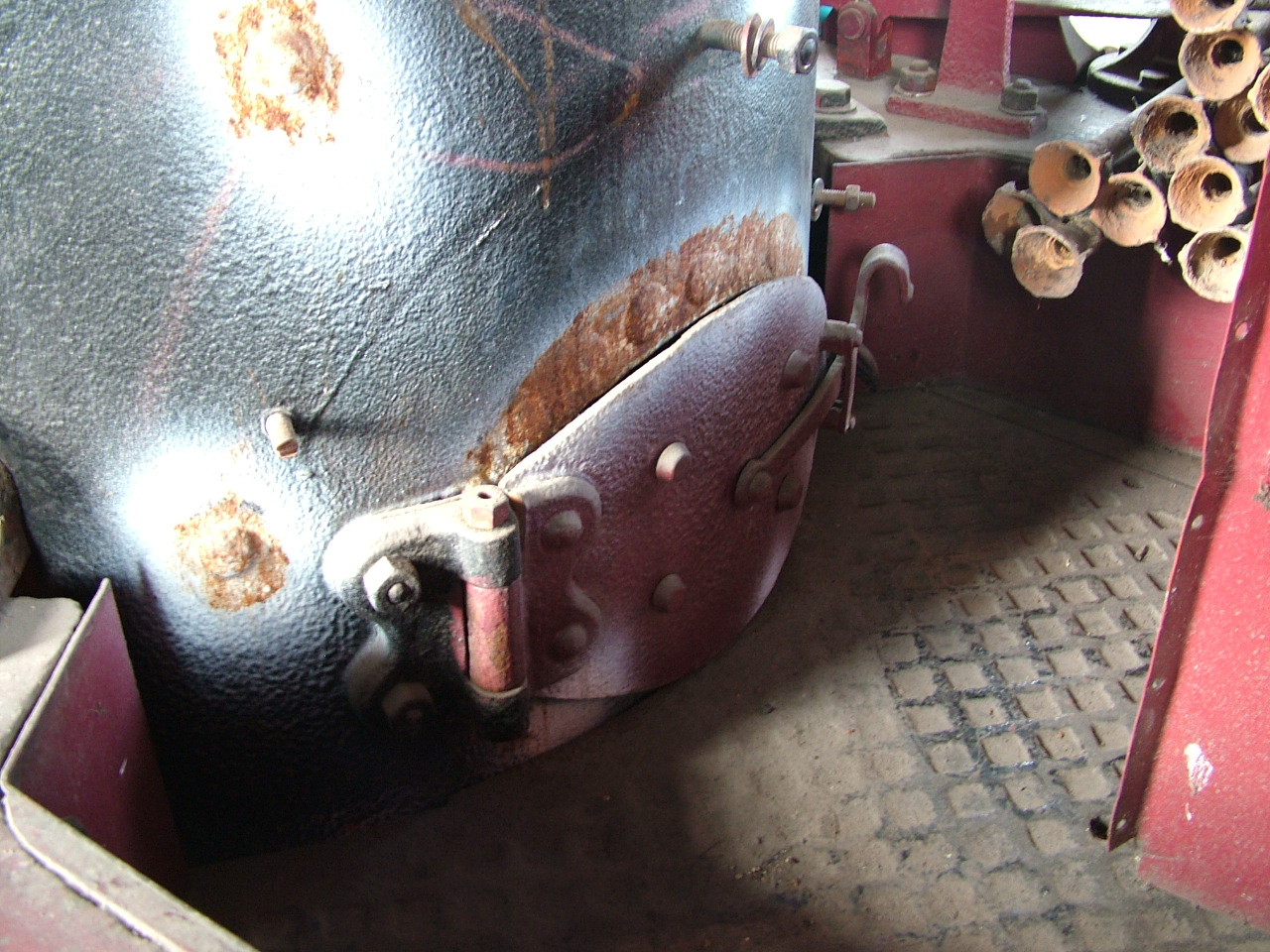
Below: The view through the firebox door, showing the blanked ends of the tubes seen above.

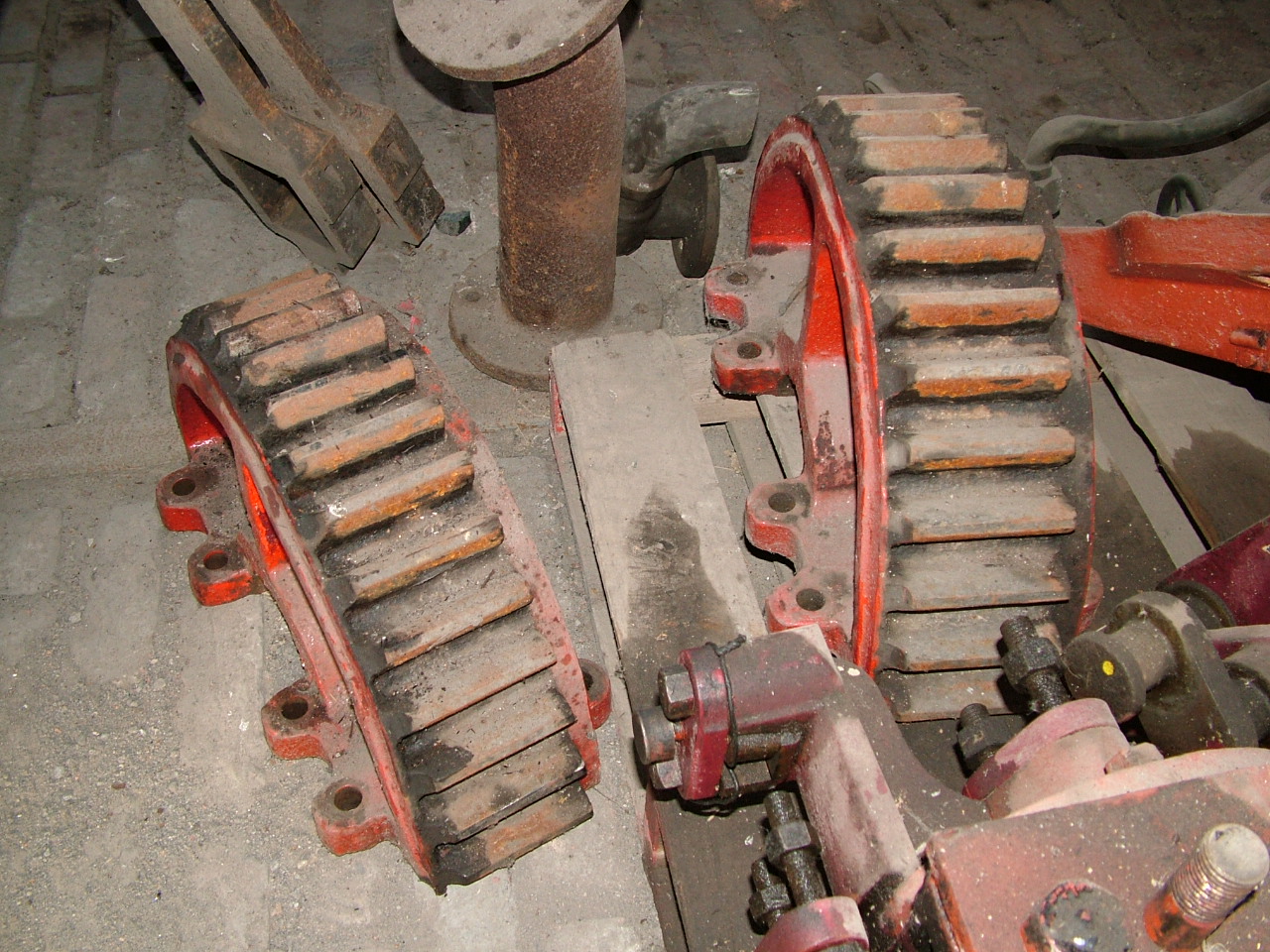
Below: The cylinders and associated mechanical components had been removed (in the 1990s) when the boiler was being subjected to the NDT and design change process referred to in Part 1. Here the two-piece final drive gear that clamps onto the front axle is seen, with one of the cylinders just visible to the bottom right.
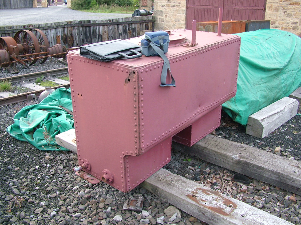
Below: The wrought iron water tank was in good shape, stored outside and requiring very little work to ready it for further service. Iunderstand the dent was inflicted by the replica Locomotion No.1’s chimney!
Restoration commences…
Below: The project was very lucky to attract National Lottery (as it was then) funding, under the ‘Your Heritage’ process. This enabled a focus on the locomotive’s regional connections to be made and also enabled us to consider the construction of a new boiler for Coffee Pot. Other steam locomotive restoration projects had been advised that new boilers would not be approved, these not being under the same scheme. I don’t know if this has subsequently changed, but it has led to some boilers being so heavily rebuild under the guise of an overhaul, that they could be considered new in everything but name. We also received funding from the Friends of Beamish (which paid for the boiler survey, drawings and submission inder the Pressure Systems Safety Regulations), the Beamish Development Trust (whose fundraiser also worked on the Your Heritage application) and some private donations too. We match-funded with my time, as well as the extensive volunteer hours that Dave Young contributed to the project.
As part of the scheme, we installed an exhibition inside this Portacabin in the Colliery Yard – its placement here is not as alarming as it seems, as the adjacent yard was a building site during the construction of the lamp cabin, so this was just one portable building amongst many!

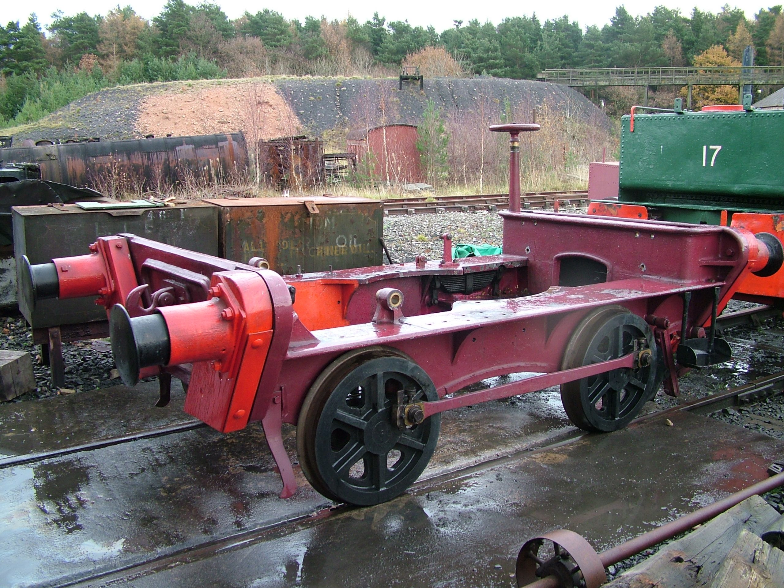
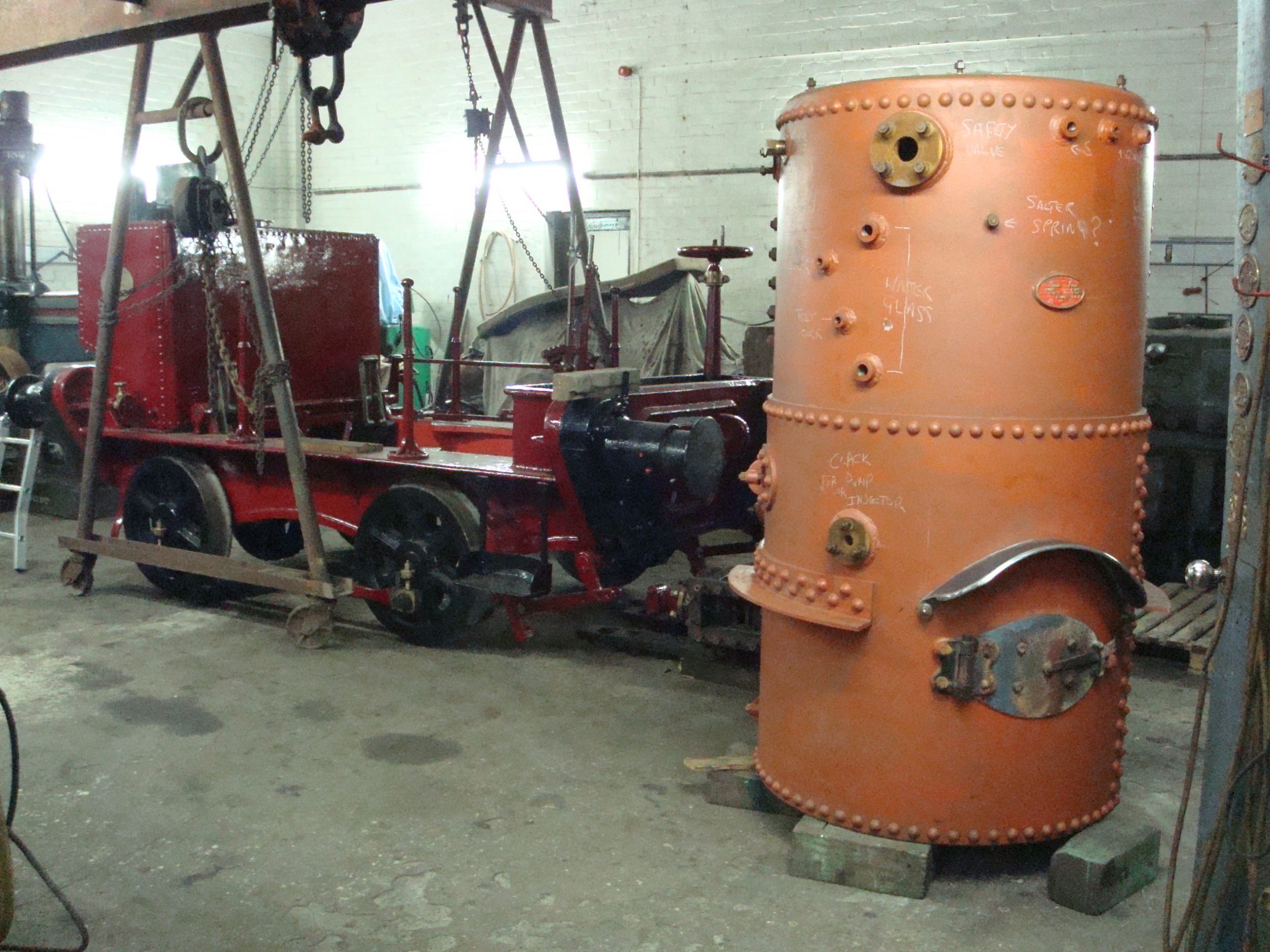
Below: 30/11/2006 Boiler and cab removed. Rolling chassis steam cleaned (along with HW 33/1873 which was to receive a cosmetic restoration using some funding from the Renaissance in the Regions scheme that was in operation at the time and was funding curatorial staff and programmes of collections work – this enabled us to take No.17 back to Seaham Harbour – for more on this see the history of No.17 here: http://beamishtransportonline.co.uk/2020/04/shdc-no-17-a-history-and-review/
Below: 10/01/2007 – Frames lifted from wheels and packed. Journals and bearings examined and found to be in very good condition. Note that Wellington had returned to the Tanfield Railway by this time.
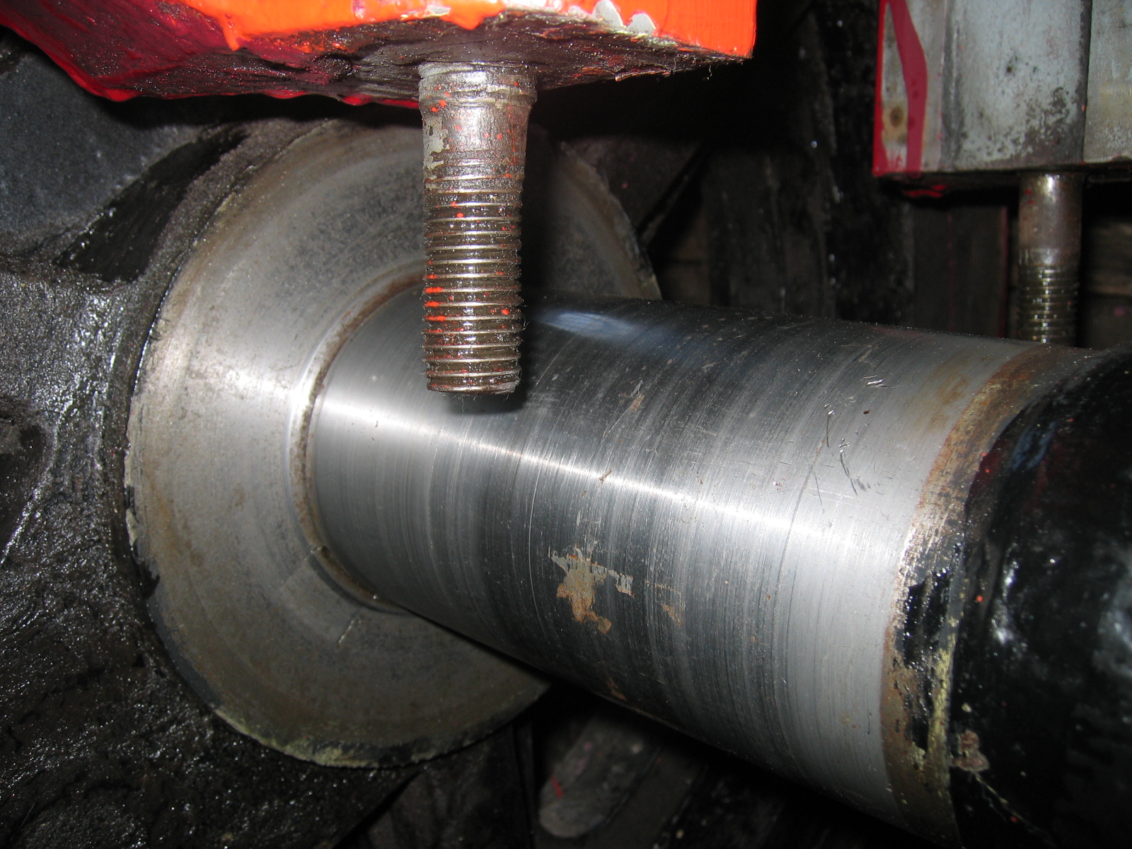
Below: A closer view of one of the journals, and the thrust face to the rear of a driving wheel. The inspection revealed that these were fit for further service and enabled work to proceed on the rest of the chassis.
Below: There was a lot of scraping and rubbing down to do in preparation for the repaint, and then a lot more flatting and painting to follow. Dave and I spent many hours working on the paintwork, for which I selected SC Crimson, from the Craftmaster range, as most suitable. The buffer beam planks were painted red originally, and we did try this – but it looked awful against the crimson, so we repainted them black, which enormously improved matters! One was found to be in poor condition and was replaced as part of the restoration.
Below: The regulator quadrant – seen here with a significant crack through the casting. It also had the difficult feature of being attached to the boiler with horizontal bolts, rather than vertical, which meant these had to be inserted into the shell and sealed as it hugged the boiler shell. It is an important component in the story as I am pretty sure this is what I had in my hand as I walked out of the office one day and met a gentleman who commented on it and then inspected it more closely. Upon explaining the difficulty, he offered to help – eventually making a new pattern and machining a replacement (with vertical locating holes so it could be mounted onto studs, and false bolt heads for appearances sake). That man was Dave Young, who would later contribute enormously to the steam engineering programme at the musuem, including Coffee Pot, No.18, the Steam Mule, Samson and many other jobs. A serendipitous meeting!

Below: 13/05/2008 – work is well underway on repainting the chassis, with the white tent erected to protect the paintwork when the varnish was applied.
The CMP section on the appearance of the locomotive is worth reproducing here, as it shows what we were hoping to achieve (and 13 years on, I think we have been successful in this):
Appearance and finish should reflect 1870s condition namely well cared-for, but essentially a working locomotive in an industrial environment. Original surfaces should be pitted rather than mirror-finish, though some thought is to be given to the ‘nearly new’ nature of the locomotive at the time it is intended to represent it. The paintwork must be applied in an authentic manner, i.e. not sprayed and using traditional application methods. Polishing of the paintwork should be restricted to using oil with a drop of rape seed oil to give a warm tone to the paintwork.
Brightwork and brass should be clean, but not polished to a high shine as every care is to be taken to maintain an ‘in industrial service’ appearance. [A loving wipe with an oily rag…]
Crazing or cracking of smokebox paint is to be considered part of the natural weathering process, except where bare metal becomes exposed. In such instances, patch re-painting of this area is considered acceptable.
Livery itself is difficult to determine. No colour record appears, nor are colour photographs available. Black and white photographs show such a layer of dirt and lime dust as to completely obscure the colour beneath. Other Betchworth locomotives were a red/maroon shade (sometimes described as Indian Red – itself a difficult colour to accurately identify over time — the North Eastern Railway used this description, the shade, however, being akin to red oxide), and as this is commensurate with typical locomotive practice (for industrial builders) in the 1870s, a dark crimson/maroon finish has been selected. Should evidence to the contrary of this be found, this will be detailed and added to this document with a view to correcting the livery at a future repaint.

Building a new boiler…
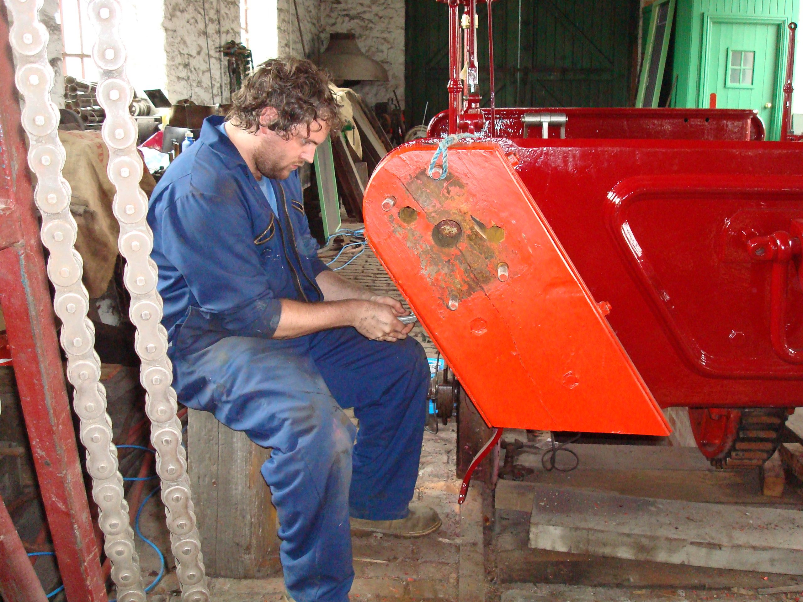
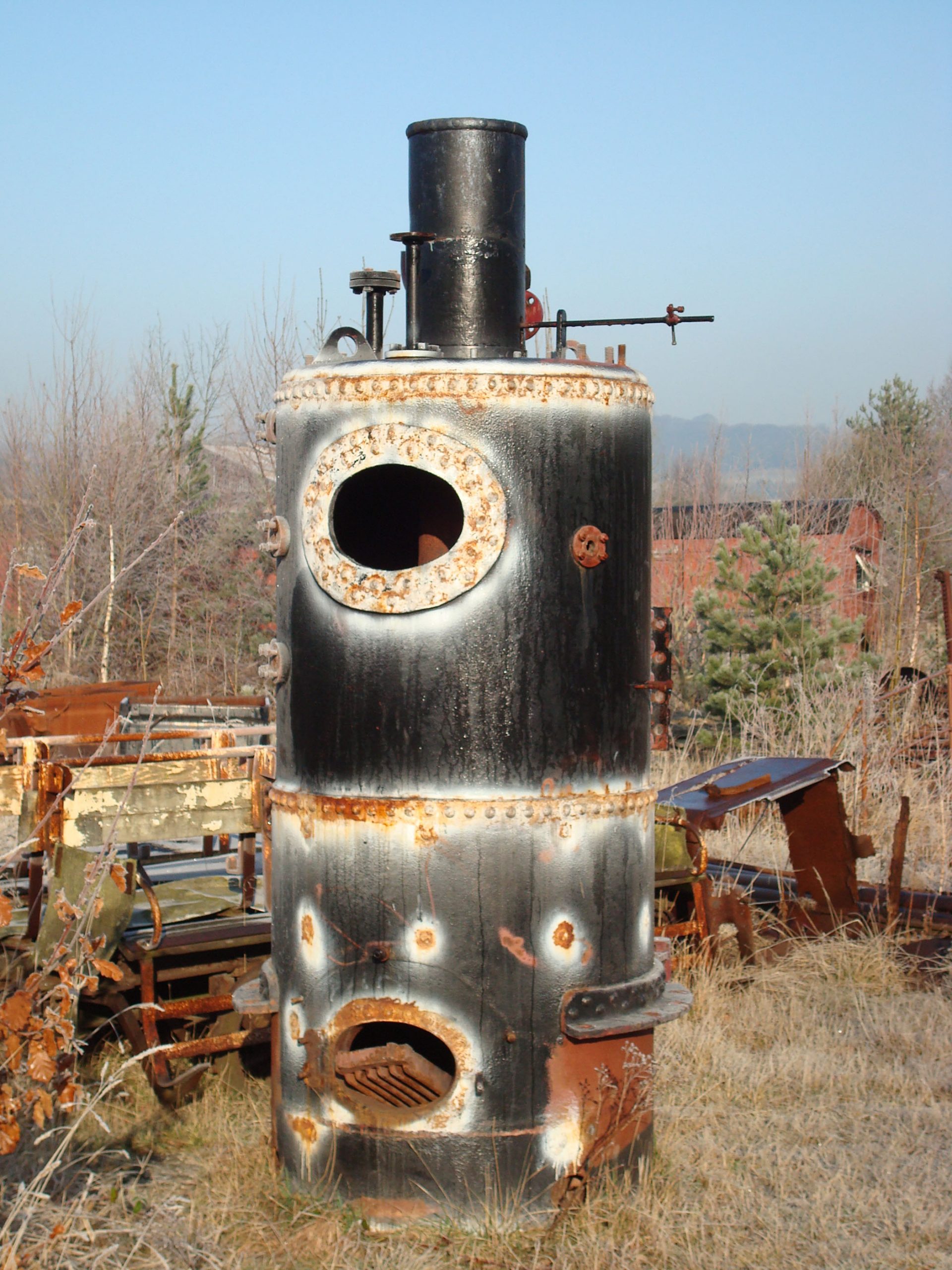
Below: The fourth boiler, stored outside and which is retained as part of the material record of the locomotive. It will probably be cosmetically tidied up and placed next to a stationary engine in due course, to give it some context (remember this wasn’t actually a railway locomotive boiler design). The sizable inspection door is readily visible here.
Below: Having decided to build a new boiler, we had to create a design, for which Graham Morris was appointed. He surveyed HW 21 (Seaham Harbour’s No.16) which was at the time on display on a roundabout in Stockton-on-Tees, and which usefully (for us) retained its original boiler. The design was then submitted for approval by a notified body and then tendered for construction. Israel Newton & Sons, from Idle near Bradford, won the contract (coincidentally, the firm having a long history of boilermaking, including vertical boilers for industrial appliacations and with a history dating back to 1803).
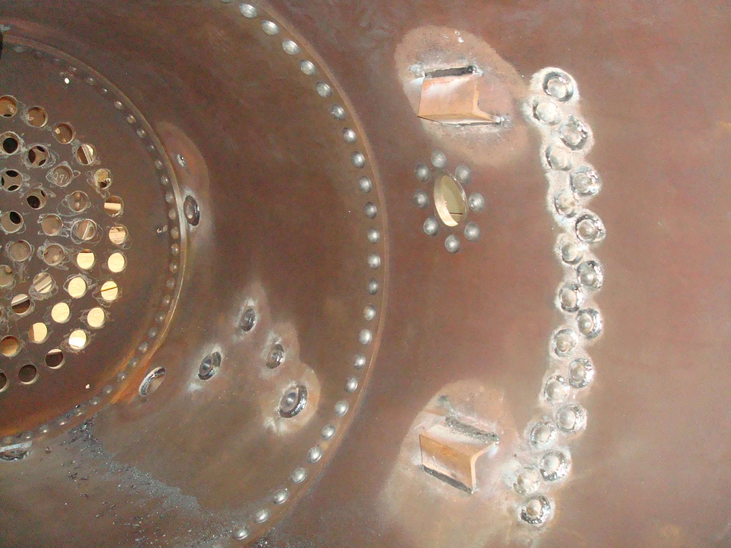
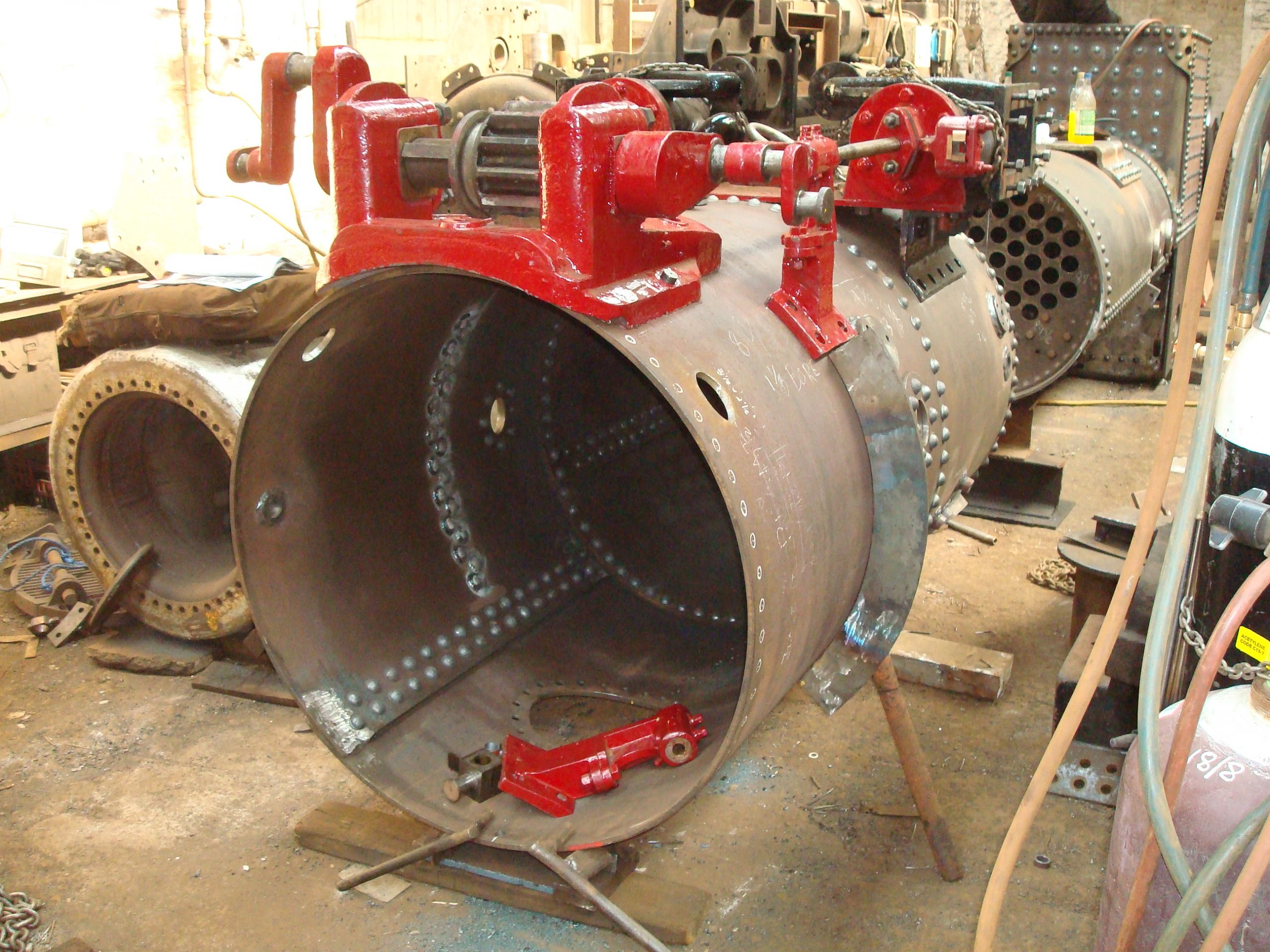
Here is a view inside the shell, looking towards the top of the firebox (note the tubeplate to the left). The little angles are where the water arrives into the boiler via the clack valves and were included to deflect cold water from the inner firebox, which was not fitted at this time and would occupy the space we are looking into. Note the various weld-sealed rivets (those to the right being for the angle brackets that mount the boiler onto the frames) and seal-welded bushes (for the various steam take-off points such as the blower, whistle and steam pump).
Below: A view of the outside of the shell, with the castings for the cylinders, rod guides and the one which carries the crankshaft located and being prepared for drilling. Blind bushes were used wherever possible and the firm’s experience in setting up traction engines proved to be invaluable here – the boiler expanding in length (or height in this case) when hot and so altering the final positioning of these key mechanical components.
Below: A closeup view of the overhauled cylinder block, placed atop the brackets that secure it to the boiler.

Below: The clack (or check) valve (the one shown being an original fitting from SHDC No.17) is a non-return valve that enables water to be admitted to the boiler under pressure, but prevents the contents of the boiler coming back out (usually!). Sometimes these valves stick, and to prevent steam exiting via the injector and feed pump inlet pipes to the overflows, or to isolate the clack valve for maintenance purposes, a long bolt is fitted to screw the valve down onto the seat. When they stick, they can be encouraged to close again with a wooden plank or brake-stick – whence the battle scars worn on this example, despite the deep polishing it has received.
Below: We manufactured three valves for the project, two for No.18 and one for Coffee Pot. Dave Young made the patterns and also carried out the machining work, so we have what is a ‘standard’ part for Beamish’s Colliery locos now. The first view below shows the valve seat (right) and valve itself (left). The second view shows the machined clack valve body. In operation, one of the castings proved to be very porous and was re-cast for us (entailing yet more machining work).
Below: One of the refurbished slide valves, which controls the admission and exit of steam in the cylinders, enabling the double-action of the engine. The valves were in a poor state and David Young made patterns for new castings, which he subsequently machined and fitted to refurbished valve rods (which had become badly pitted). The original valves had worn to such a state that they had previously been repaired by screwing on shims of metal. These have deteriorated and the concern we had was that the shims might detach themselves in operation, damaging the port faces of the cylinder casting. The lock nuts (brass and steel in the photographs) enable the valve to be adjusted on the rod, to give an even timing to the valve events (or regular ‘chuffs’ if you like!).
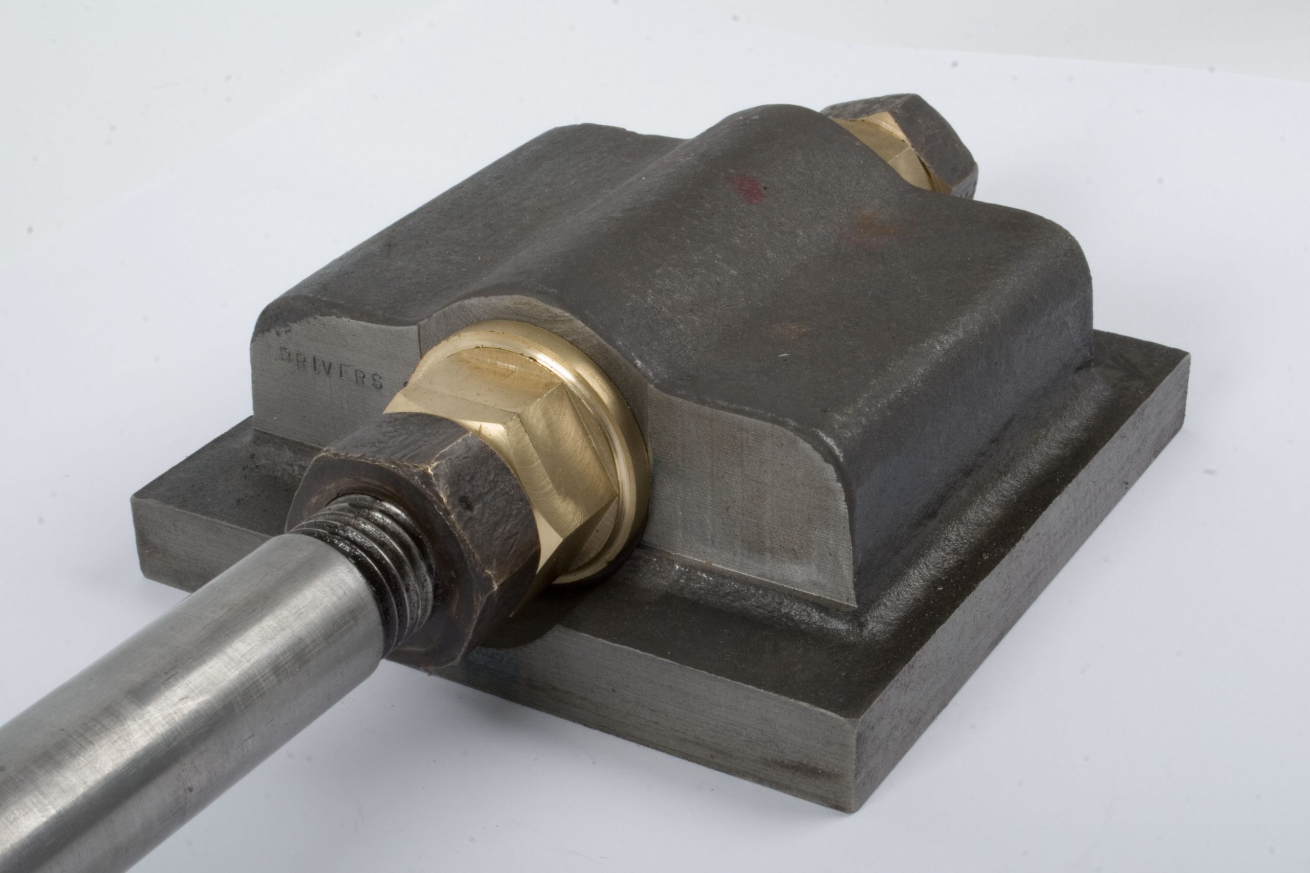
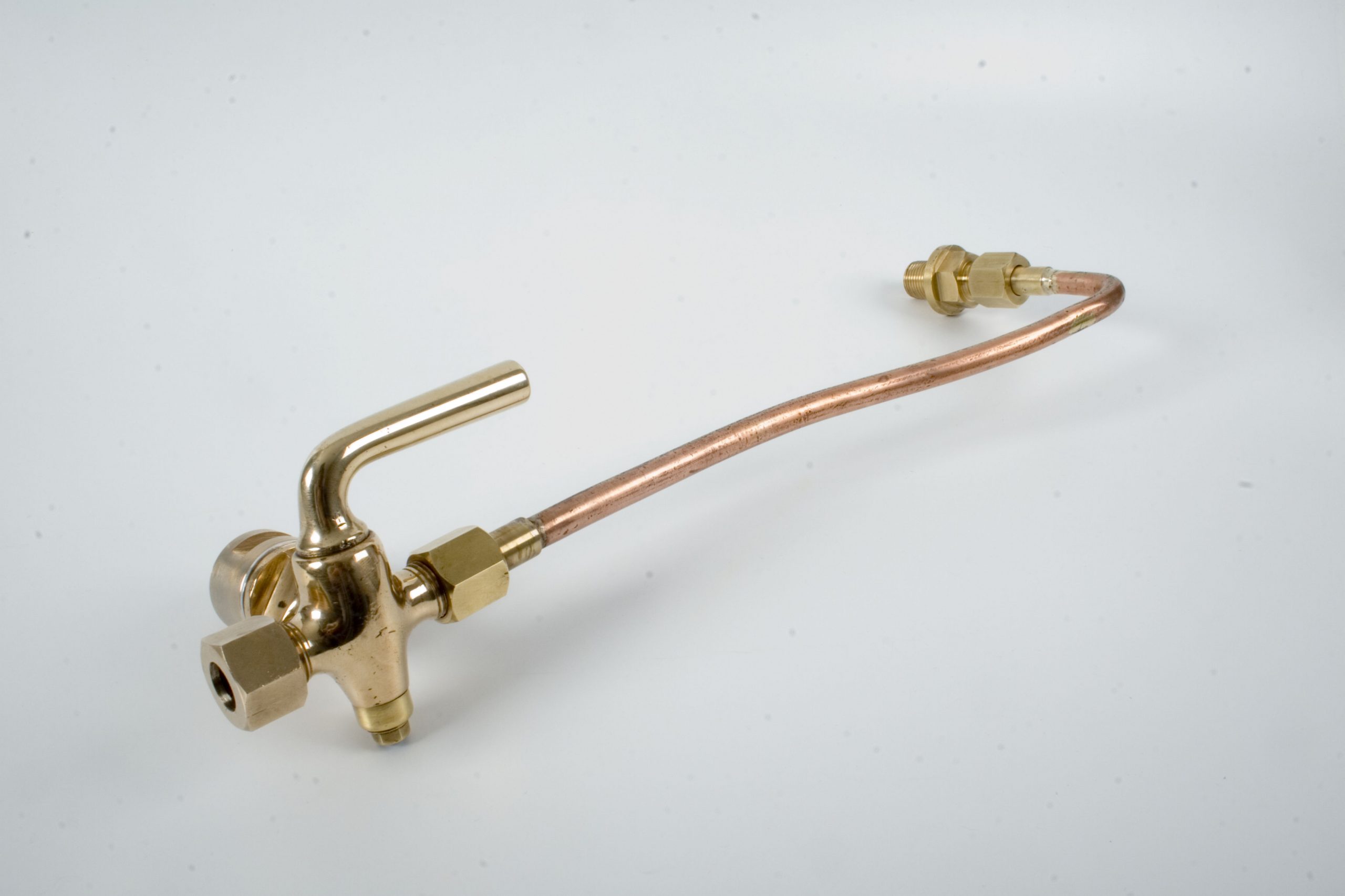
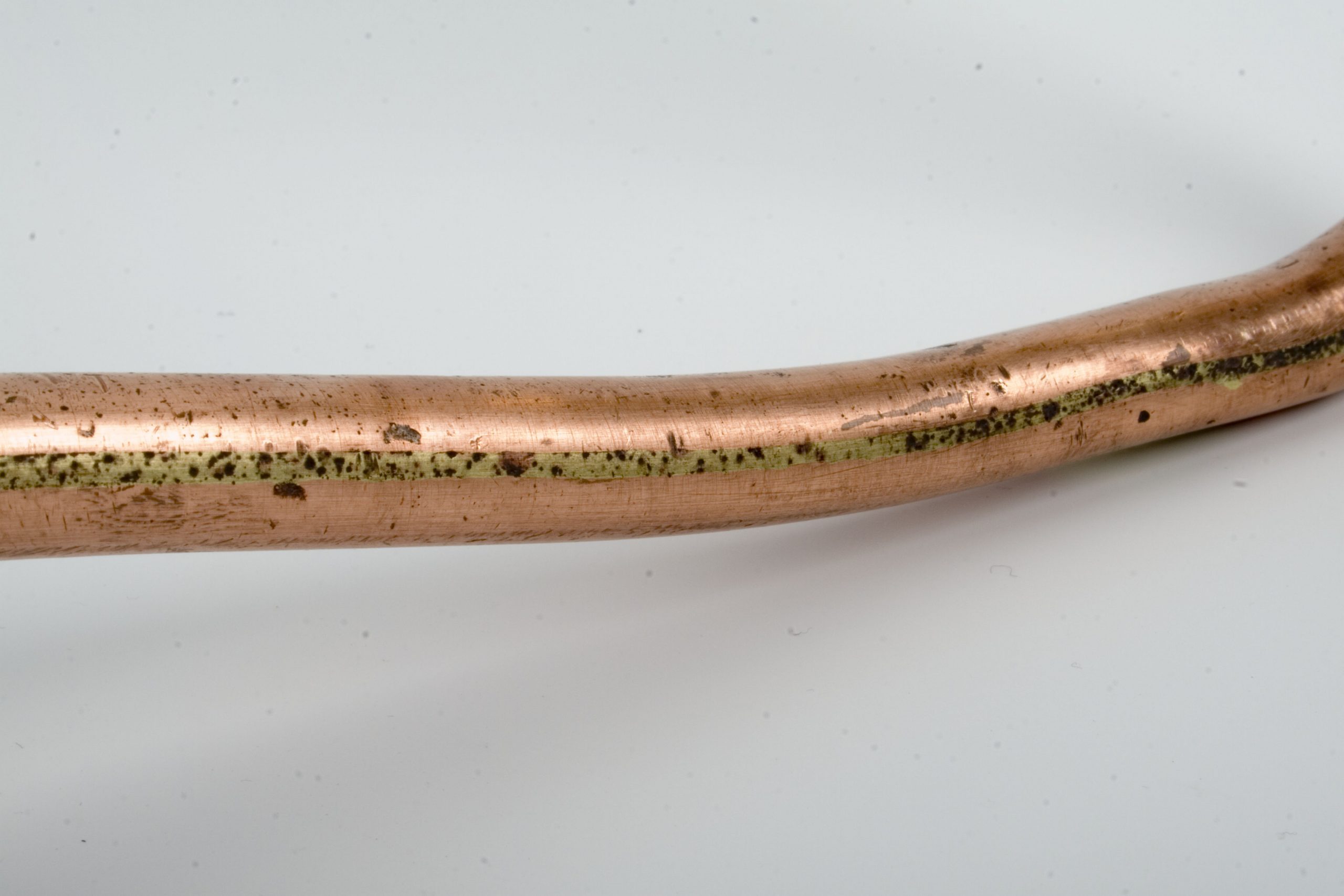
Below: These views show the cylinder drain cock assembly. Unusually for a railway locomotive, a three way single cock is used to control the egress of water and steam, meaning that the plain pipe from the upper end of the cylinder is always under pressure when the regulator is open. David Young refurbished the existing pipework and cocks. What is of particular interest is the copper pipework. This pre-dates extruded pipe and, as can be clearly seen in the photograph, it is formed of rolled flat section, then silver soldered together to form a circular section. This is another small, but fascinating part of the manufacturing process evident on a locomotive built when sailing ships were still common and Queen Victoria was still well ensconced on her throne.
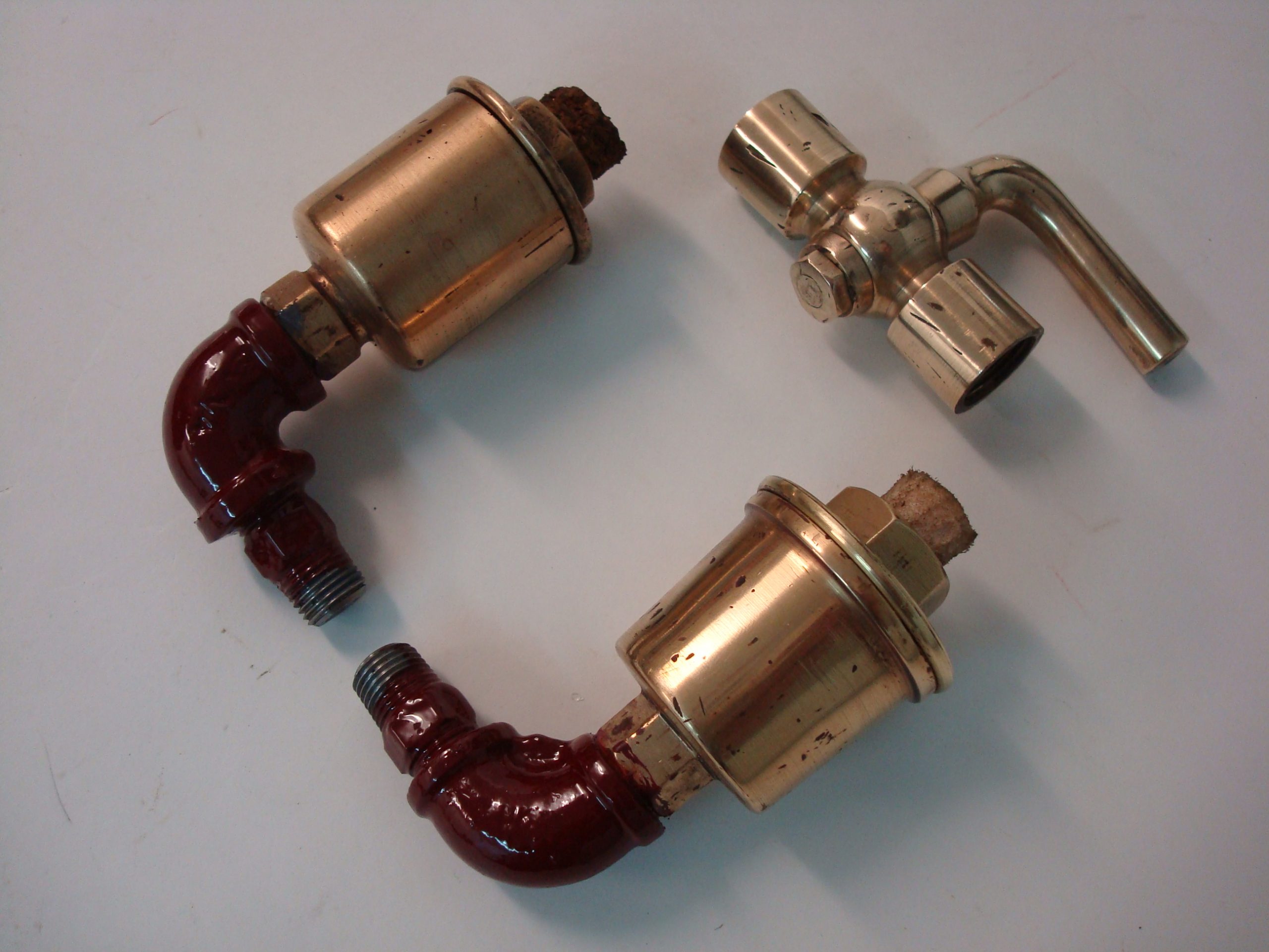
Below: More refurbishment work carried out by Dave – the two oil pots that lubricate the piston rods in their guides plus the pressure gauge isolating cock.
Below: A new safety valve to the original design was needed for the project. Fortunately that fitted to SHDC No.17 was available to us to study and Graham produced the appropriate drawings for approval (as part of the pressure system). Dave Young then made the patterns for the valve, shown here (along with the clack valve patterns). Of note is the large core box in a reversed L shape – this enables the moulder at the foundry to create a sand core to fit inside the mould for the safety valve itself, creating an internal hollow. It is located into indentations in the mould that are left by the wooden projections in the safety valve pattern – those bits painted in red oxide here. This is why patterns often have projections (and why they are painted a different colour), to enable the mould to be set up using multiple cores or patterns. The patterns are usually also labelled with what we want them made from, in this case SG Iron ( a more ductile iron that is less brittle than cast iron).
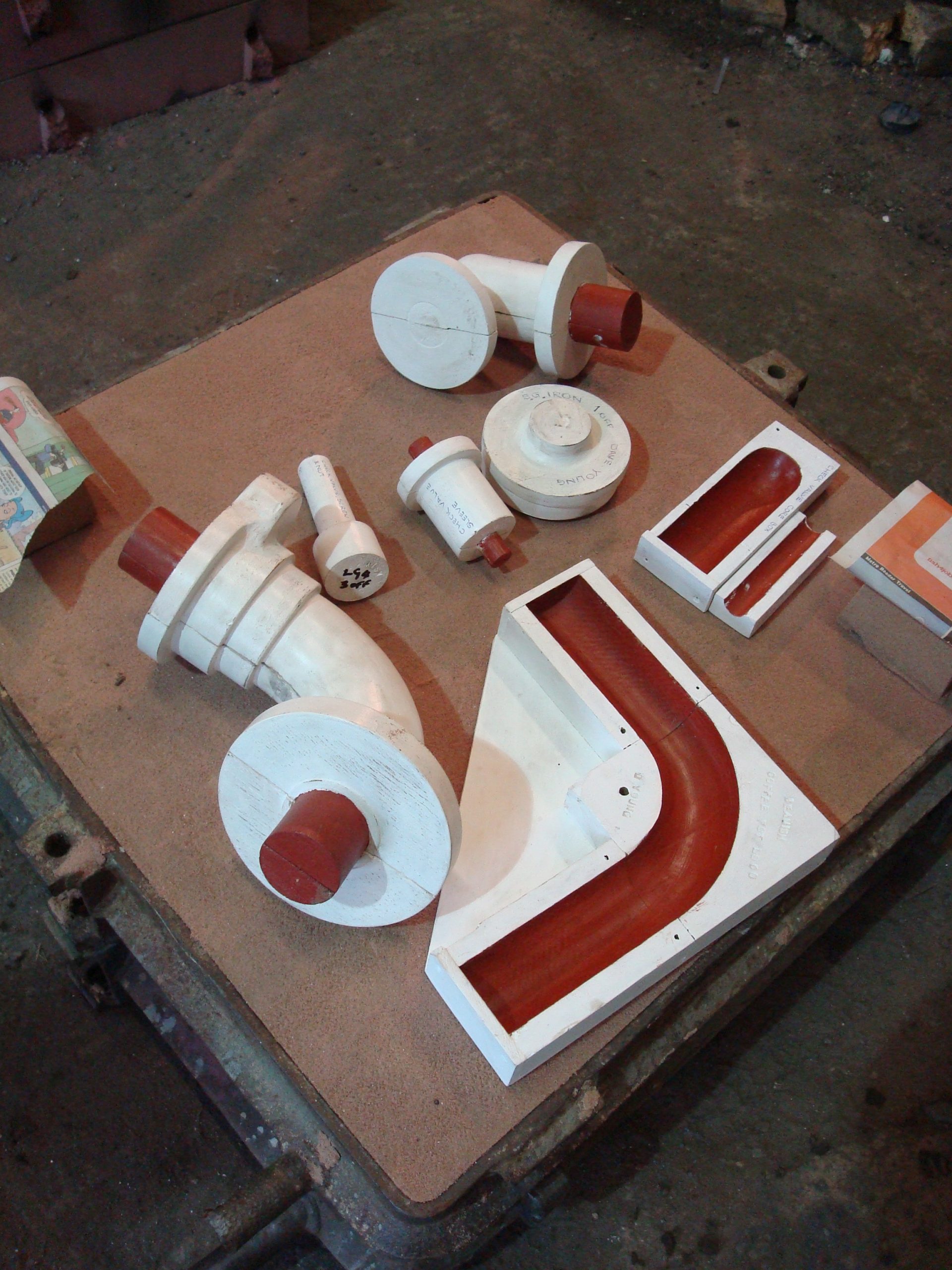
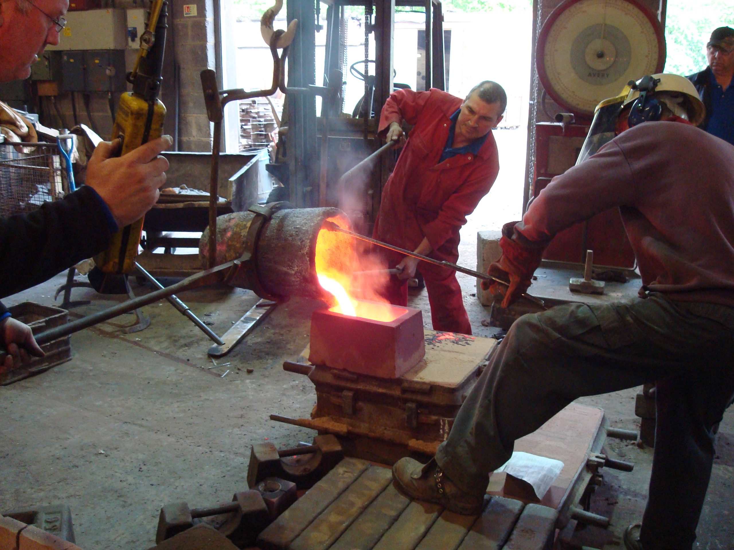
Below: The photo above showed the patterns sat atop a mould – here is a casting being created using just such a mould. The molten metal is poured into the mould then allowed to cool. Care has to be taken to enable it to cool in such a way that it doesn’t fracture or distort.
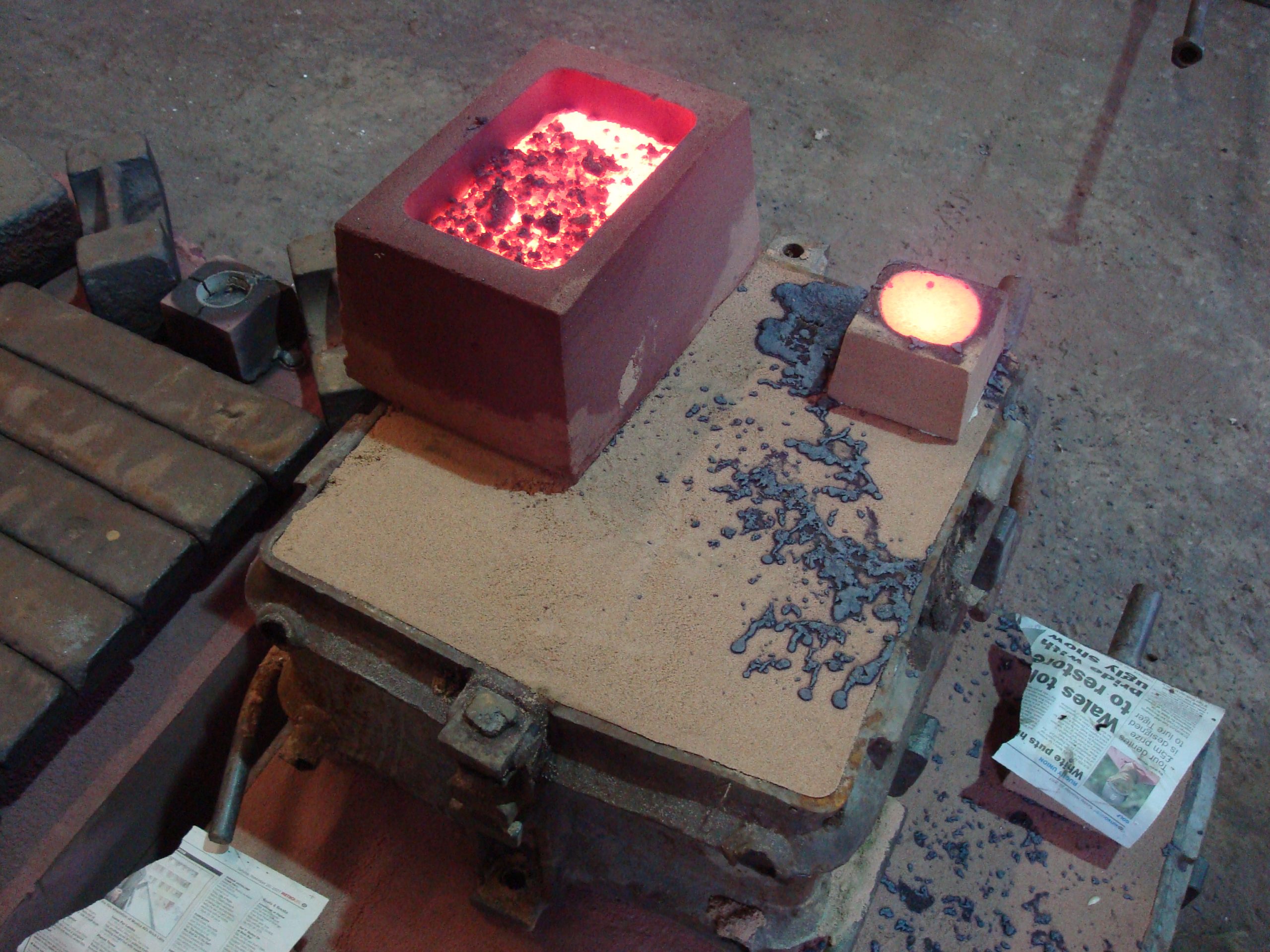
Below: Here the casting cools, note the breather hole to the right – this enables the air and impurities to escape as the molten metal is poured into the mould.
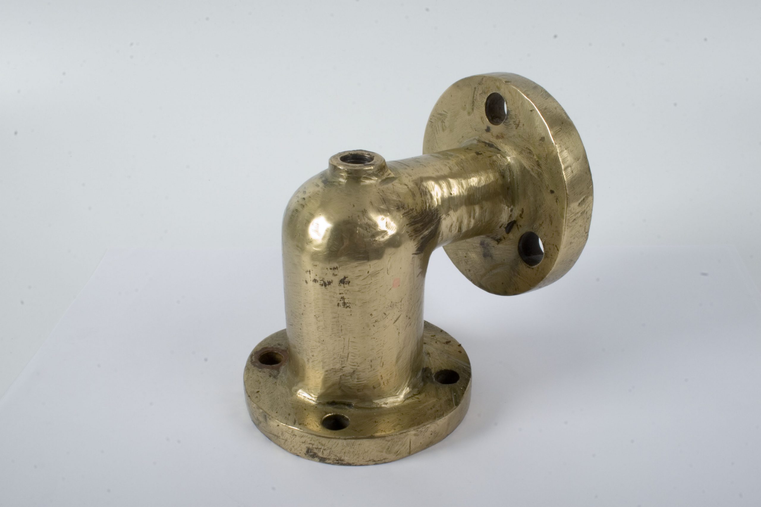
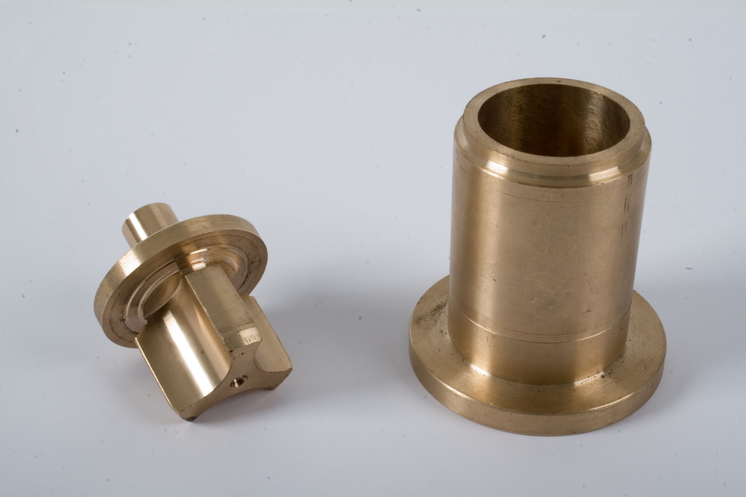
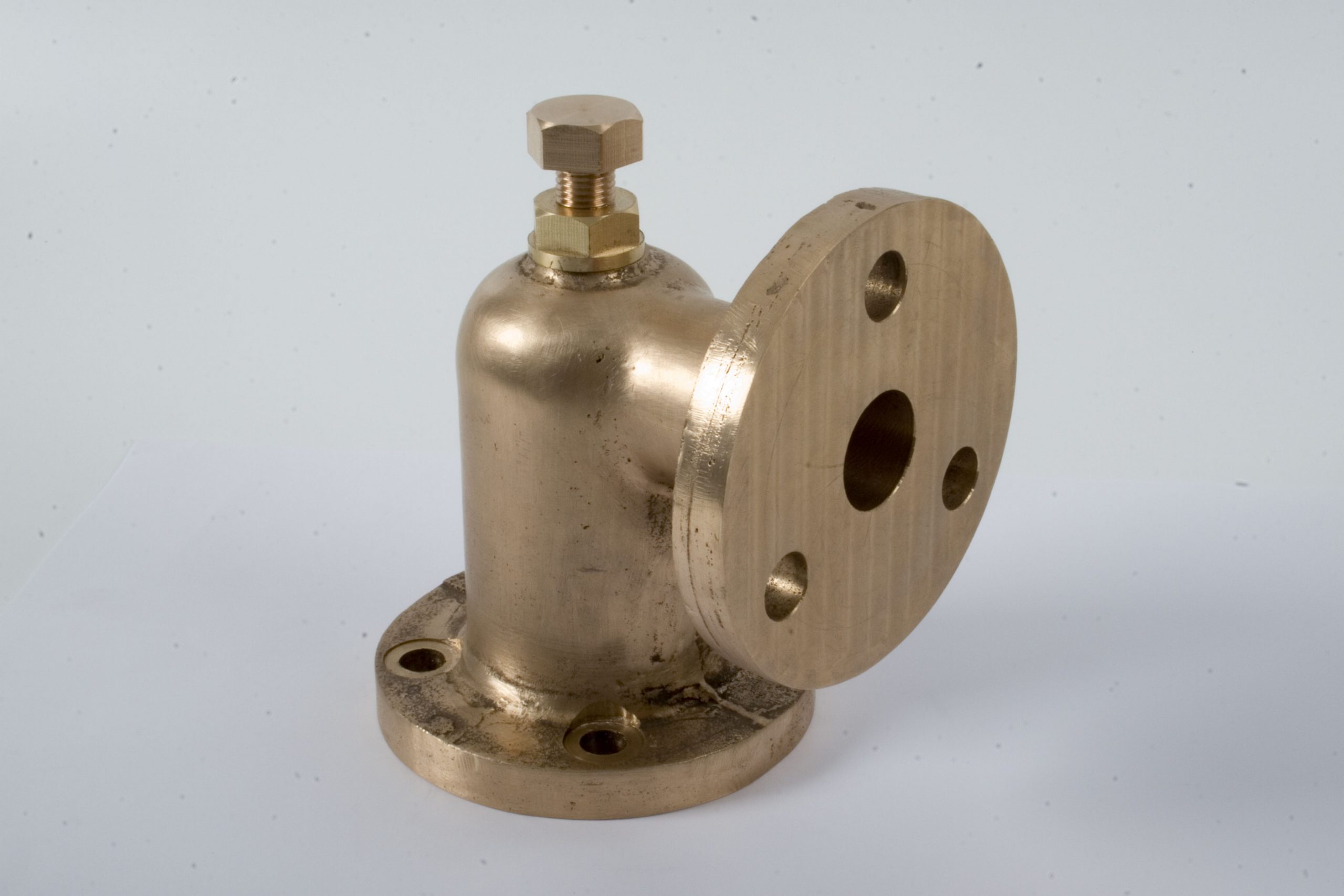
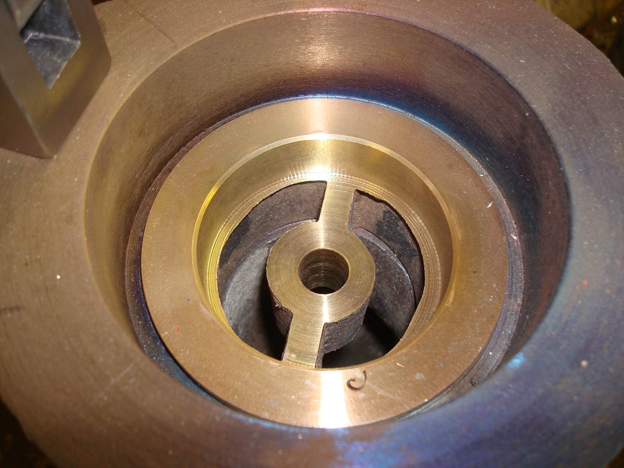
Below: Jumping ahead, here is the safety valve after machining, complete with a bronze insert for the valve to locate into.
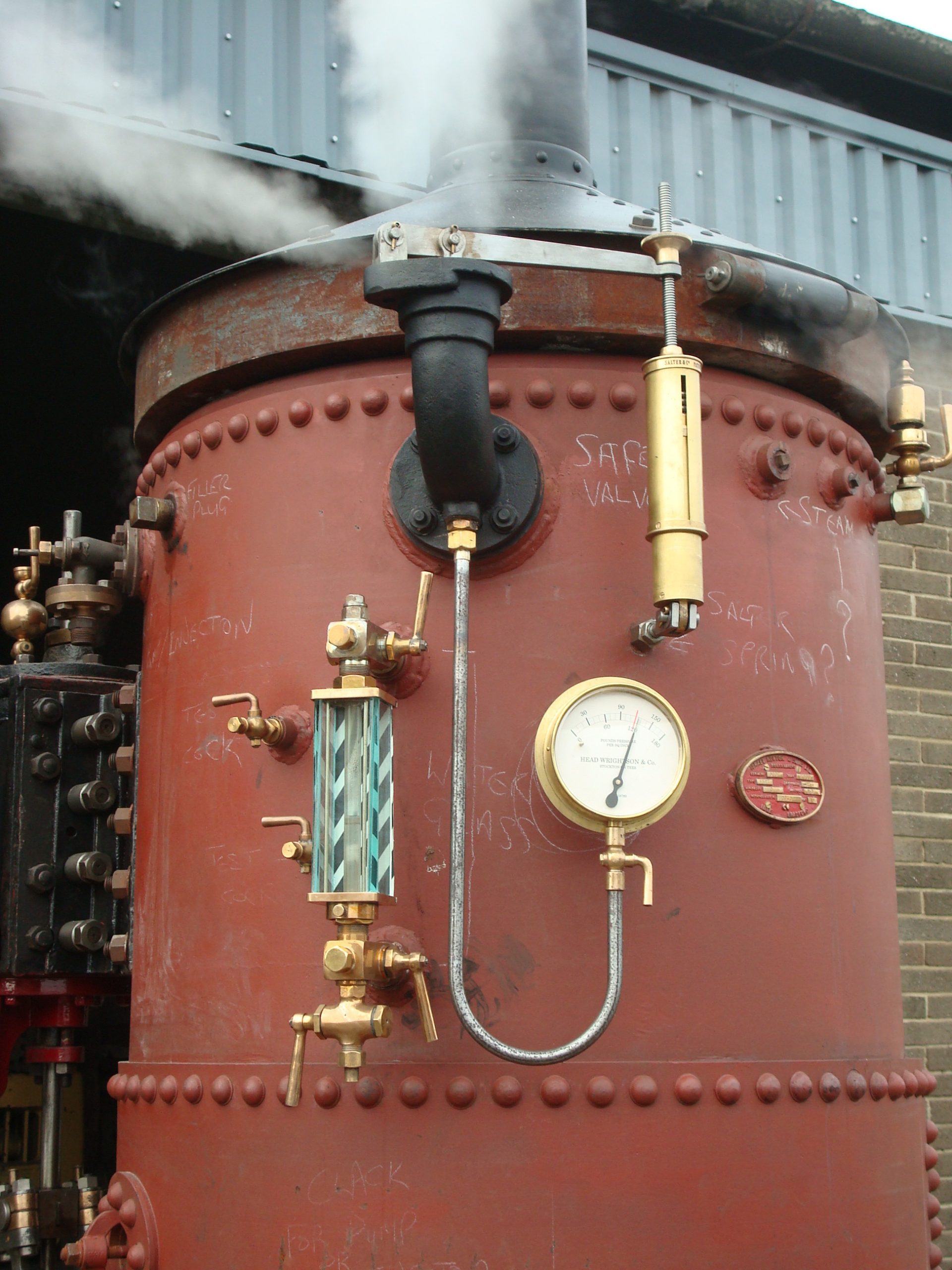
Below: This type of valve is of the Salter Spring type, where the valve is held closed by a spring, located at the end of an arm. The arm is seen here, mounted on one side of the valve casting and with the rod holding the valve to its seat a little further along. A rounded end to this enables the valve to adjust itself slightly, helping it to seat better when the steam pressure reduces below the set parameters.
The spring is mounted at the other end of the arm, enclosed within a brass case, the other end attached to a fixed point (in this case an anchor into the boiler barrel). The steam pressure builds beneath the valve, which is held closed by the spring balance, until the desired release pressure is reached, at which point the pressure overcomes the spring and pushes the valve open. On a Salter valve this process is quite gradual, the downside being that it can take quite a decrease in pressure to fully seat the valve once the pressure has dropped below the maximum working pressure allowed (indicated by a red line on the pressure gauge). A second safety valve casting was created at the same time, for the future restoraiton of SHDC No.17…

Below: In September 2009 the locomotive’s rolling chassis was relocated to the workshop of Allen Engineering in Hetton-le-Hole, not far from the museum. Here, Vincent and Frankie Allen would apply their considerable steam experience to completing the assembly of Coffee Pot, testing the engine and manufacturing the bits and pieces (such as boiler cladding) that merge all of the sub-assemblies into a whole.
Below: The completed and hydraulically tested boiler after arrival at Beamish and awaiting collection and a move to Hetton-le-Hole with the chassis. Note the cylinders and crankshaft casting in the foreground. The small cog can slide on its shaft, enabling the engine unit to be disengaged from the locomotive. We use this feature to warm the engine up and remove as much condensate as possible before Coffee Pot goes into service (we shall look at the hot showers it treats drivers to in Part 3).

Below: After arrival at Allen Engineering, with boiler first to receive attention.
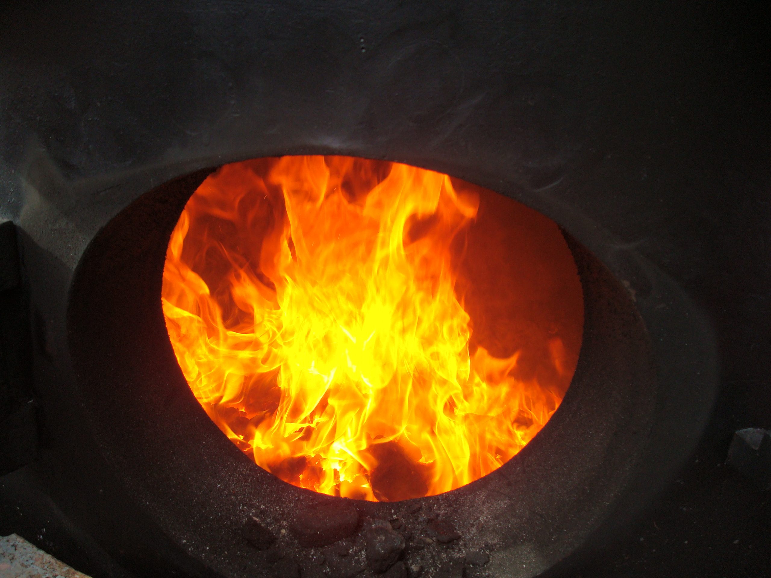
Below: Such was the rate of progress that in November 2009 the first fire in the new boiler was lit…
Below: The boiler, seen here in a bespoke cradle, was steam tested out of the frames for the insurance company surveyor. Note that the cylinders and other castings are now in place, the smokebox has been manufactured and the boiler fittings are all mounted. The brass tube above and to the right of the pressure gauge is the Salter spring balance, the steel safety valve arm bearing under the circular nut at the top of this.
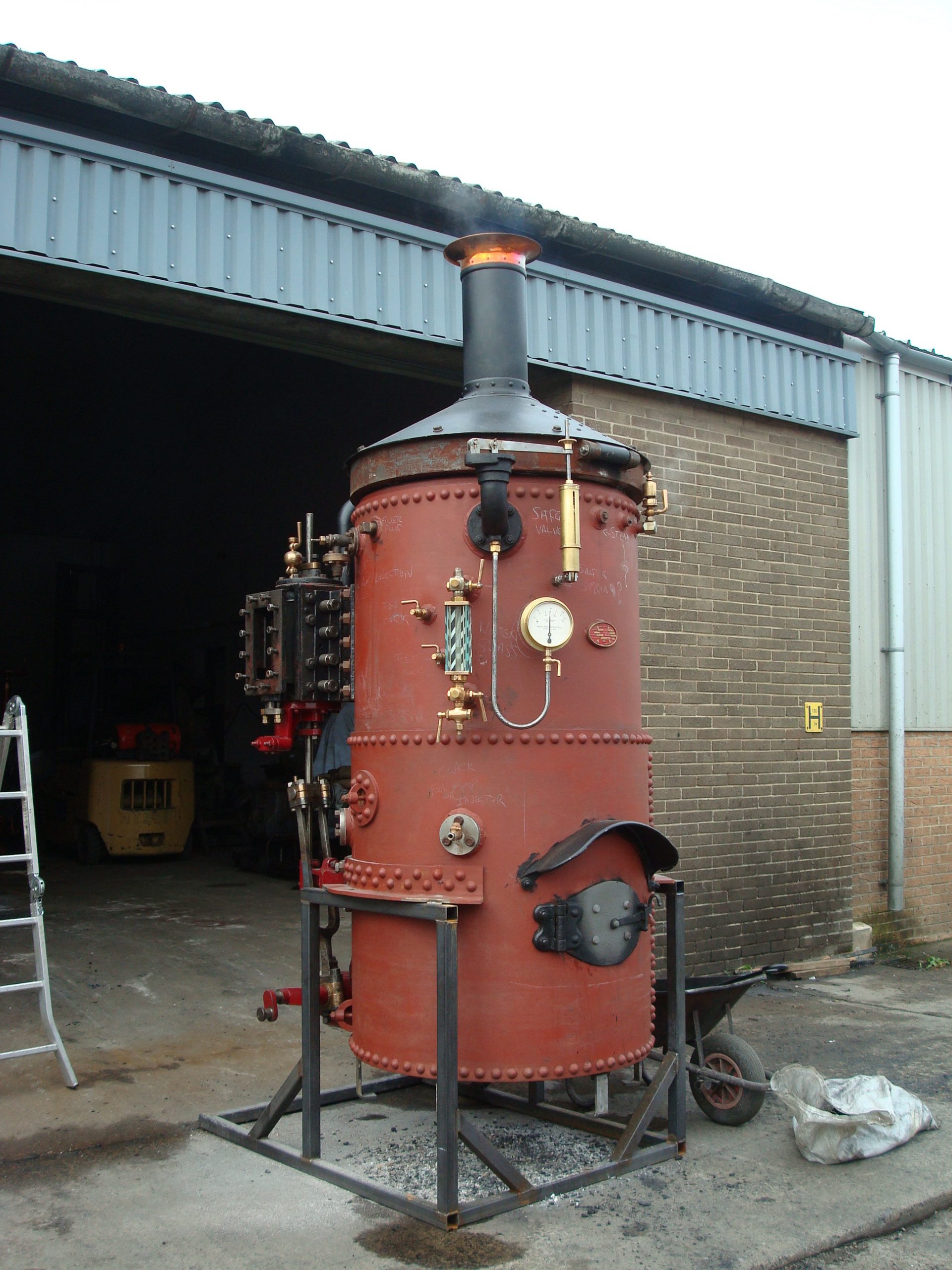
Below: The safety valve lifting durign an accumulation test (when the boiler is steamed as hard as it can be and the valve must vent the steam within certain parameters). This view also shows more clearly the safety valve spring balance and arm, and hopefully explains visually how this essential component works. The spring balance is acting to try and pull the safety valve arm (the horizontal steel item) downwards, and acts agains the steam pressure up to 120psi, at which point the spring is overcome and steam can be released. Note too the hinge on the casting atop the boiler. This was a significant and expensive item to manufacture, being a single casting that acts as a base for the smokebox and chimney (which can be opened using the hinge to enable the tubes to be swept) and also having to snuggly fit the top, smokebox, tubeplate of the boiler.
Below: With the steam test complete, work could now focus on the mechanical assembly. Here are the two piston rod guides. The crankshaft is also bolted into place (into blind bushes). A disadvantage of this method of securing is that there is no internal caulking (mechanical sealing of a joint or stud) needed (or, indeed, possible). As a result the bolts could work loose and in the end we fitted Nordlock washers, that prevent the bolts working loose in this particular location where stresses are quite high.

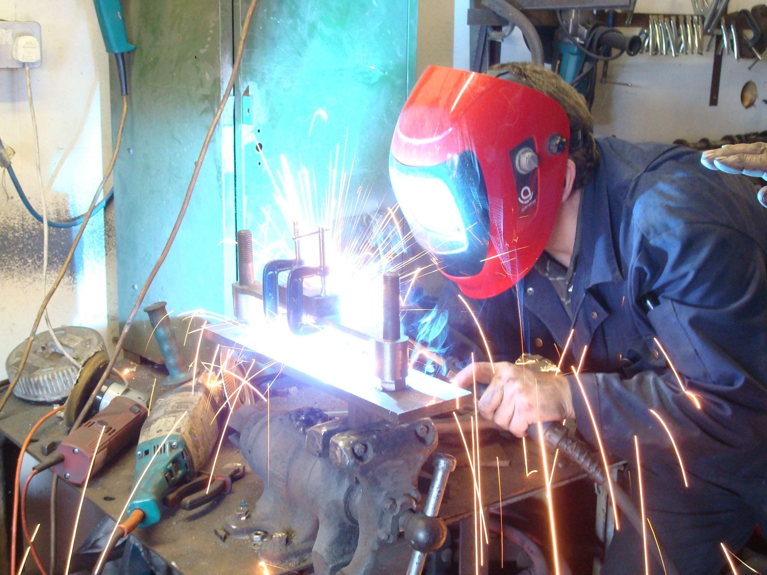
Below: Vince found that there were a number of mechanical anomolies in Coffee Pot’s valve gear, including lifting links that were not the same length. Here he welds up a link using a jig set to the correct length, ensuring all of these components were the same length, perhaps for the first time!
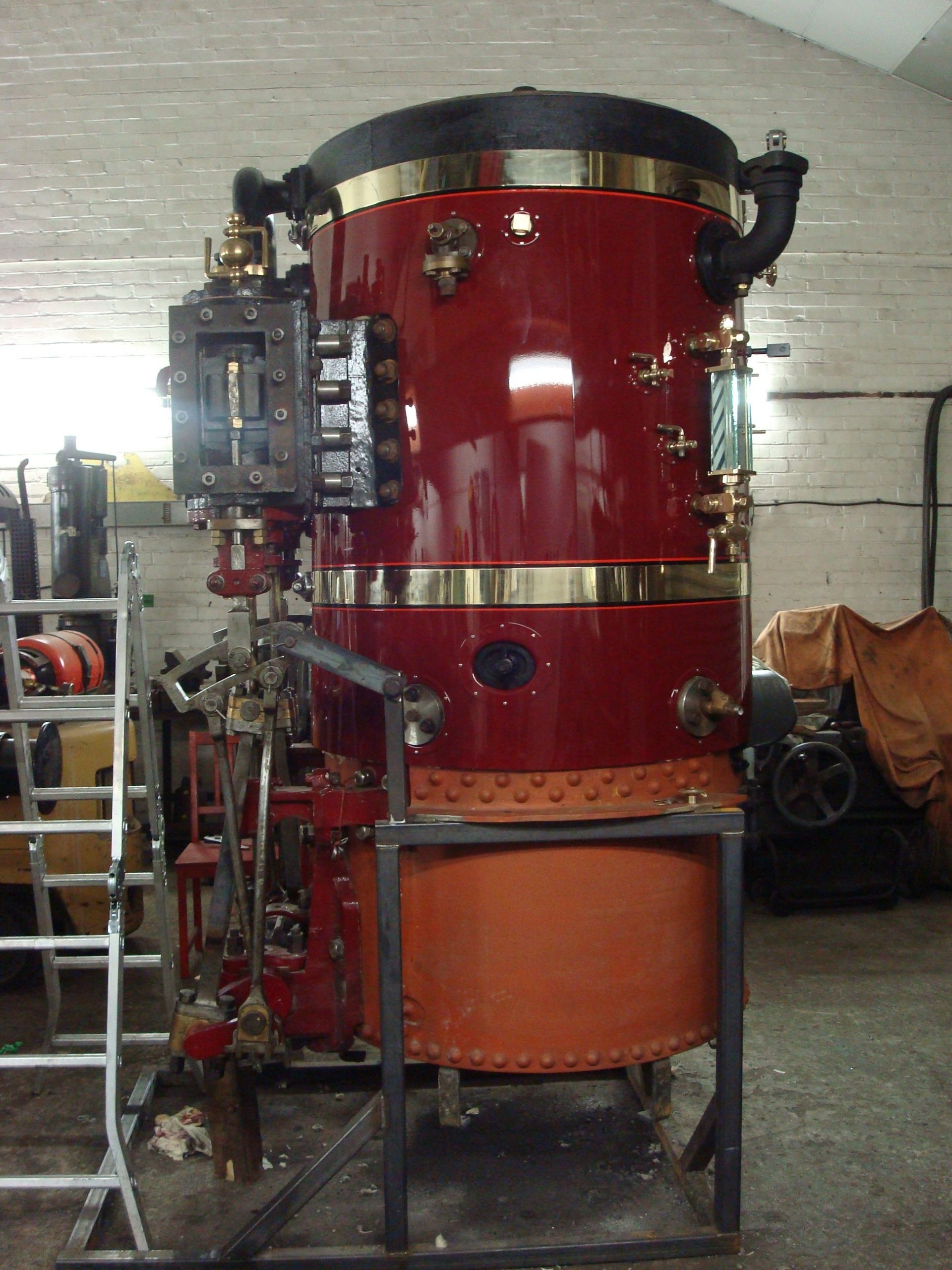
Below: Within a month of the steam test, in December 2009, the boiler cladding had been made and painted and is seen after final fitting over the lagging. The brass banding is not something readily apparent in the 1870s photos, but is very appealing and has become part of the locomotive’s appearance since completion of this overhaul in 2010. Slightly contrary to the CMP, but I do fully acknowledge this change! The supporting cradle enabled the boiler to be steamed and the engine tested, out of the frames, which allowed for a degree of controlled running-in on the bench, as it were.
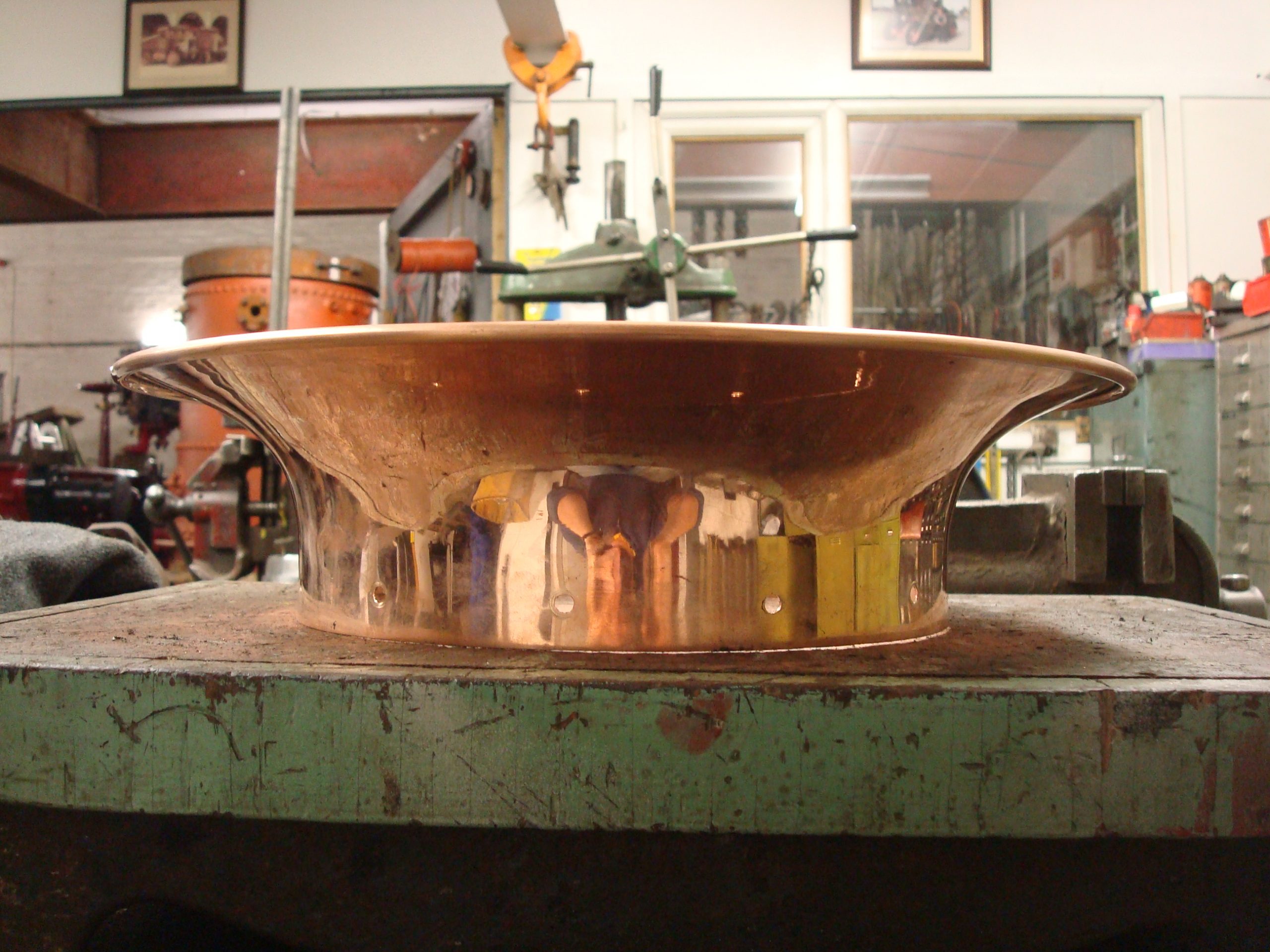
Below: The spun copper cap to the chimney is a thing of beauty and when Vince showed it to me I think I carried it around his workshop all morning – it is based on the 1870s photographs and is a superbly made item that adds to the overall restoration to a disporportionate degree. Or maybe it is just my weakness for copper-capped locomotives!
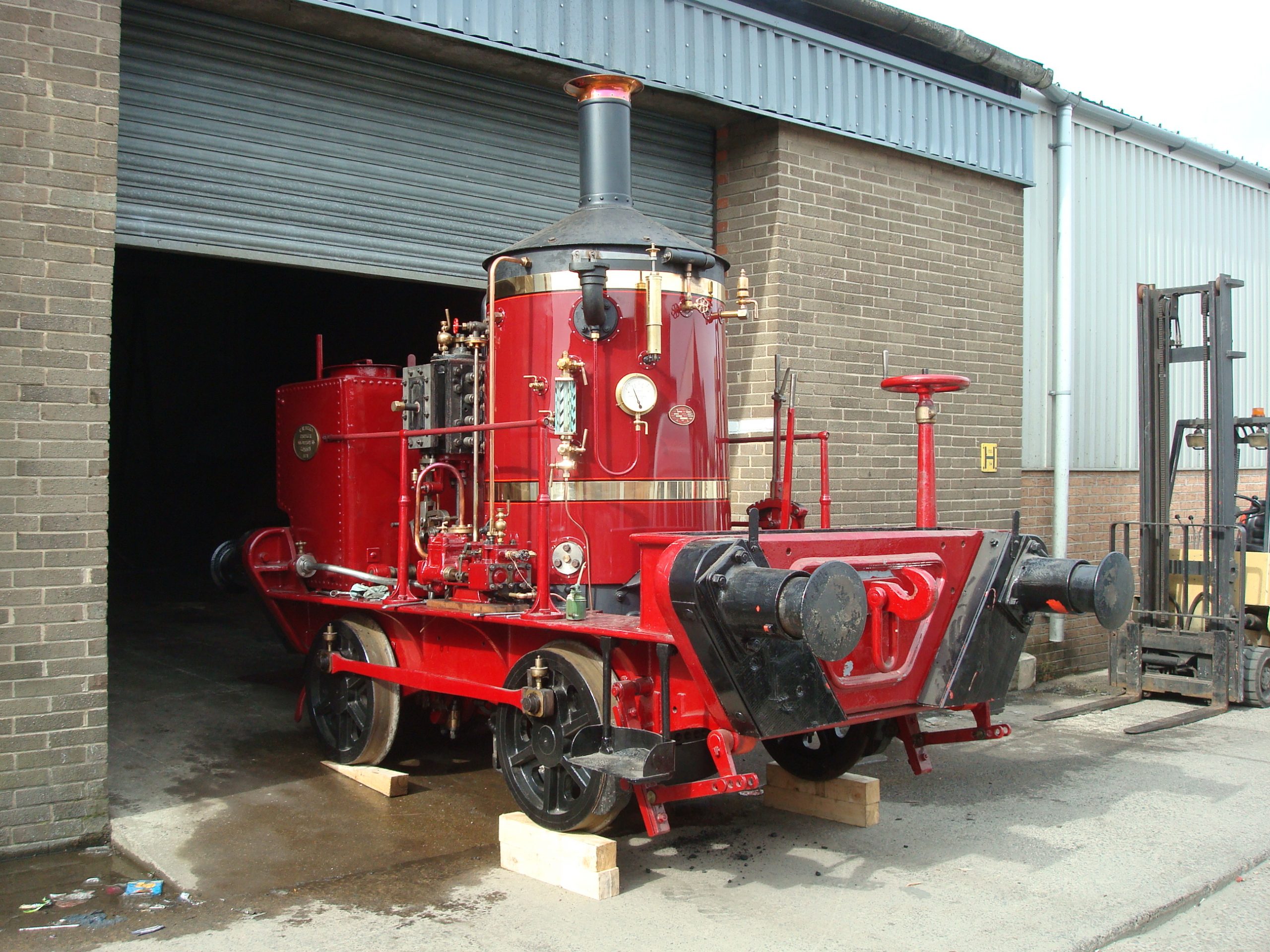
Below: In late March 2010 Coffee Pot is moved outside in readiness for a final steam test before its move to Beamish…
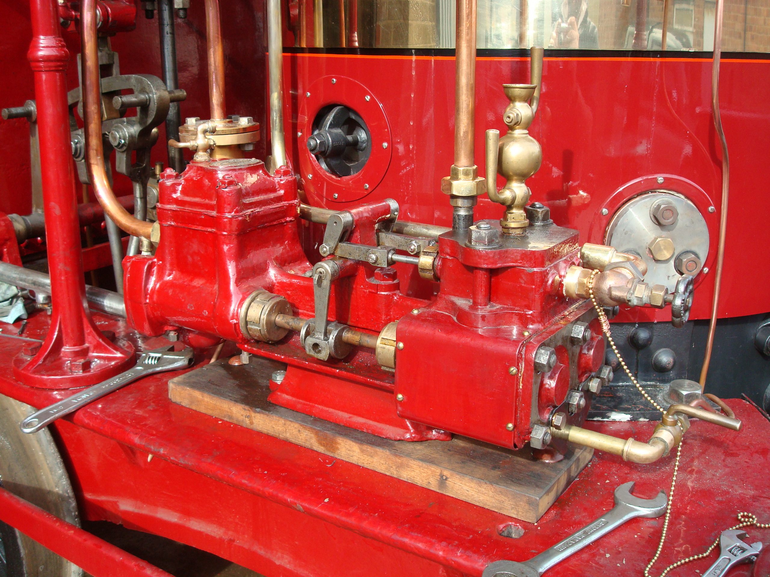
Below: This is the reciprocating water pump, the single boiler feed fitted to Coffee Pot. Built by Hickey and Son, it is a clone of the legendary (as it was both reliable and ubiquitous) Worthington Simpson pump design, of which thousands were built and worked in the harshest environments with little attention and seldom any maintenance.
I bought this example second-hand and Dave Young overhauled it at home. It is unusual on a UK railway locomotive (injectors being almost universally used for replenishing water in the boiler), and is often a source of great interest to guest drivers. It can be set, once warm, to oscillate slowly and will require almost no adjustment all day, trickling water into the boiler and only really requiring energetic bursts of activity when the boiler is being filled at the end of the day. A second pump is kept as a spare though will one day be fitted to SHDC No.17. The blanked second clack-pad can be seen in this view, where an injector or second pump feed could be installed if required.
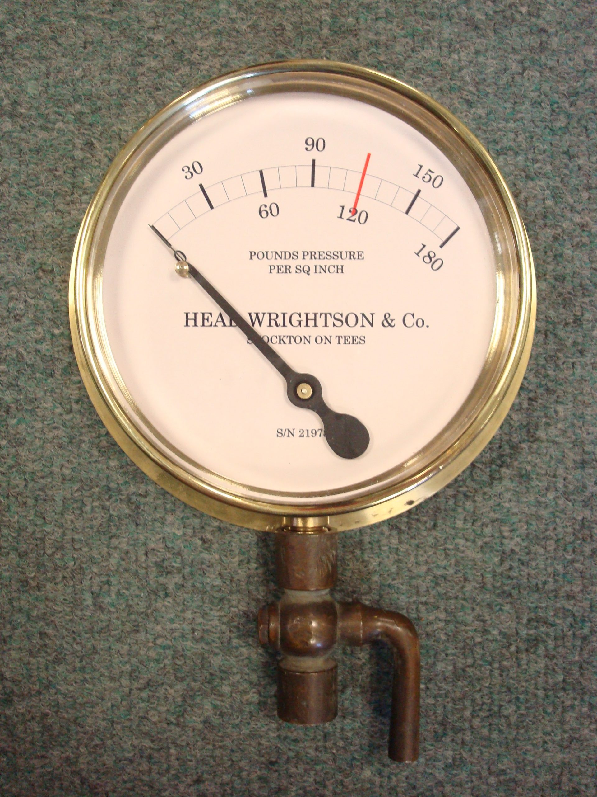
Below: A nice touch was the refurbished pressure gauge. This used a stock spare item, for which I drew a face to suit the Head Wrightson origin of the locomotive (remember it carries T. H. Head workshplates again). This was all sent to Heritage Steam Supplies who overhauled the gauge, recalibrated it and made a very professional job of creating the dial markings from my sketches. I note that they have this in their current catalogue range, though can only think we are the likely customers for another one in the future!
Below: Coffee Pot is not fitted with a damper. In fact, the ashpan is nothing more than a tray to stop the locomotive setting fire to the track. There is no means of restricting the primary airflow through the ashpan and firebed. To try and control the excessive lifting of the safety valve, a chimney damper was made and fitted – this sits within the chimney and can be rotated to impede the airflow if the locomtoive is sat for any length of time. It cannot be used when the regulator is open and it does tend to clog up. However, this is just part of the life of living with an unusual Victorian steam locomotive!
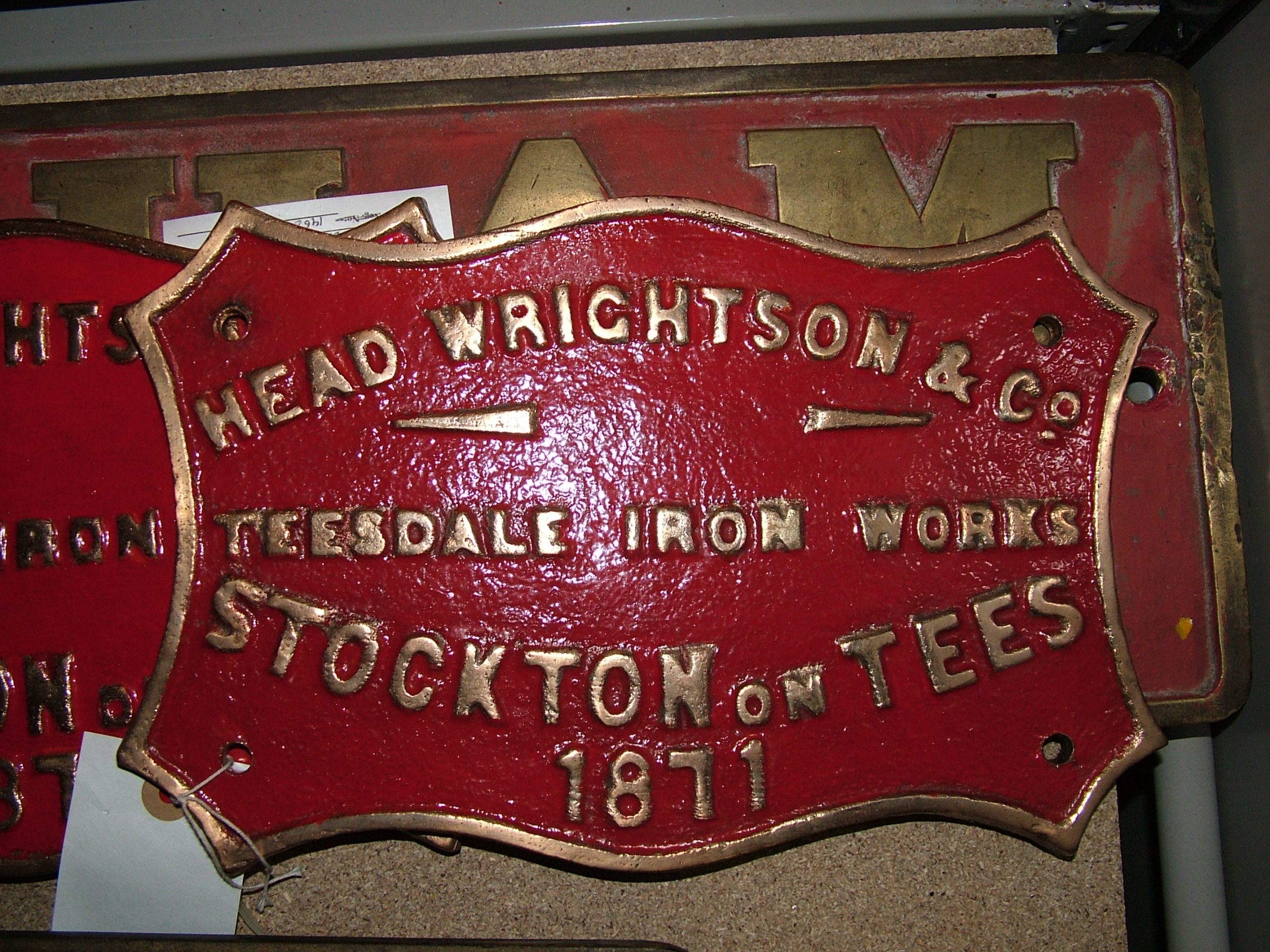
At this point it is useful to document an interesting change that has caused some confusion in recent years, namely the works plate. The locomotive was supplied with what appears to be a cast or etched plate carried on the tank side stating T.H.Head as the builder (see Part 1). This was later moved to the side frames (when diagonal bracing straps were added to the water tank). Presumably when Head Wrightson restored the locomotive, they preferred to have their own plate affixed, so cast Head Wrightson plates in the style carried by their other locomotives (wks no’s 21 and 33 — 21 already being at Thornaby having been restored). Whether 21 ‘s plate was used as a pattern or a suitable blank still existed in the pattern stores is not known. The plate was attached to the tank side as the T.H.Head one had been originally (see the photos in Part 1).
The first image shows the plate which is a replica of the T.H.Head plate and was fitted in 1984. It is thought that a beading on the edge should appear (and was missing on the 1984 examples) so new plates made for the 2007 restoration included this feature. It was felt that this point was worth recording here so as to avoid confusion in the future. In essence all the plates are replica, no originals having survived.
Below: The 1984 replica works plate, though missing the beading on the edge. Now removed and in store. This means the current replica plates are most likely the fourth set of plates carried by Coffee Pot since 1871!

Below: The HW fitted plate, that appeared in the 1960s and was not originally fitted to the locomotive during its working life.
March 30th 2010 – the big day…
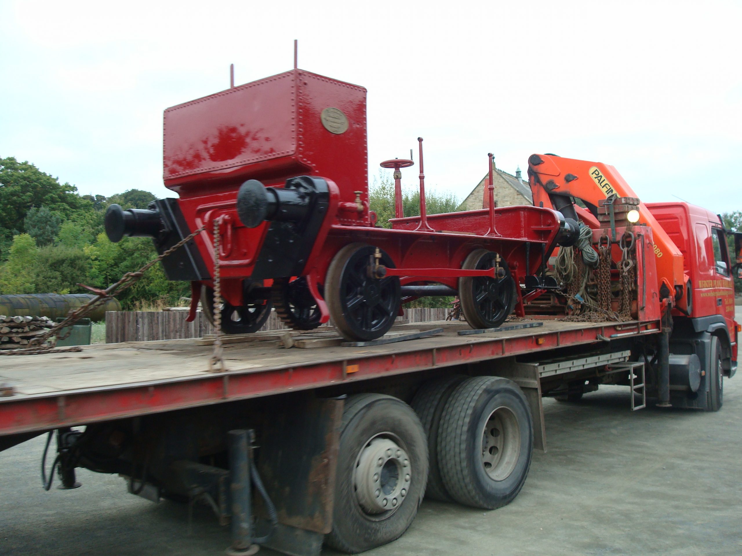
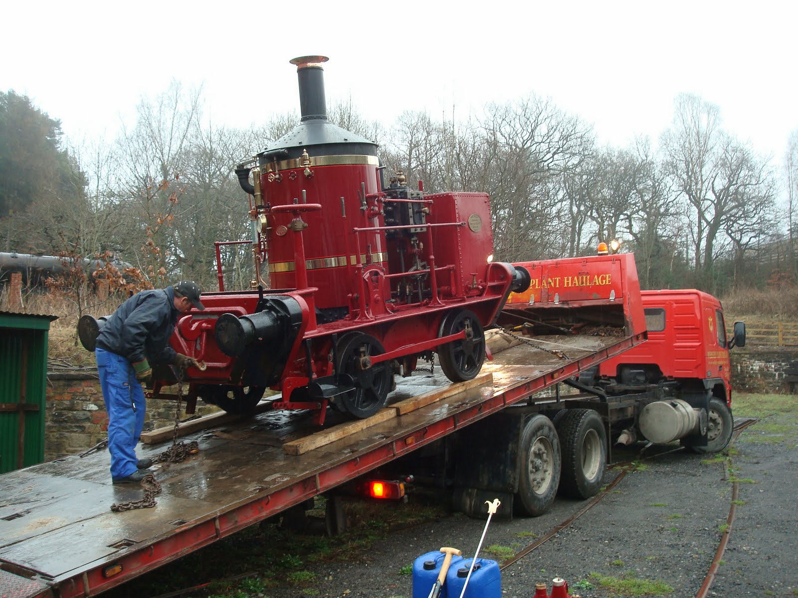
Below: At the end of March the locomotive was collected from Hetton and delivered to Beamish. As there was no satisfactory watering arrangement in place at the Colliery Engine Works at that time, the boiler was filled by hose outside the offices at Foulbridge before proceeding down to the Colliery to unload.

Below: The huge advantage of the BRIMEC lorry can be seen here, creating its own ramp to aid the unloading of the locomotive (or any rolling stock up to the weight of ten tons).
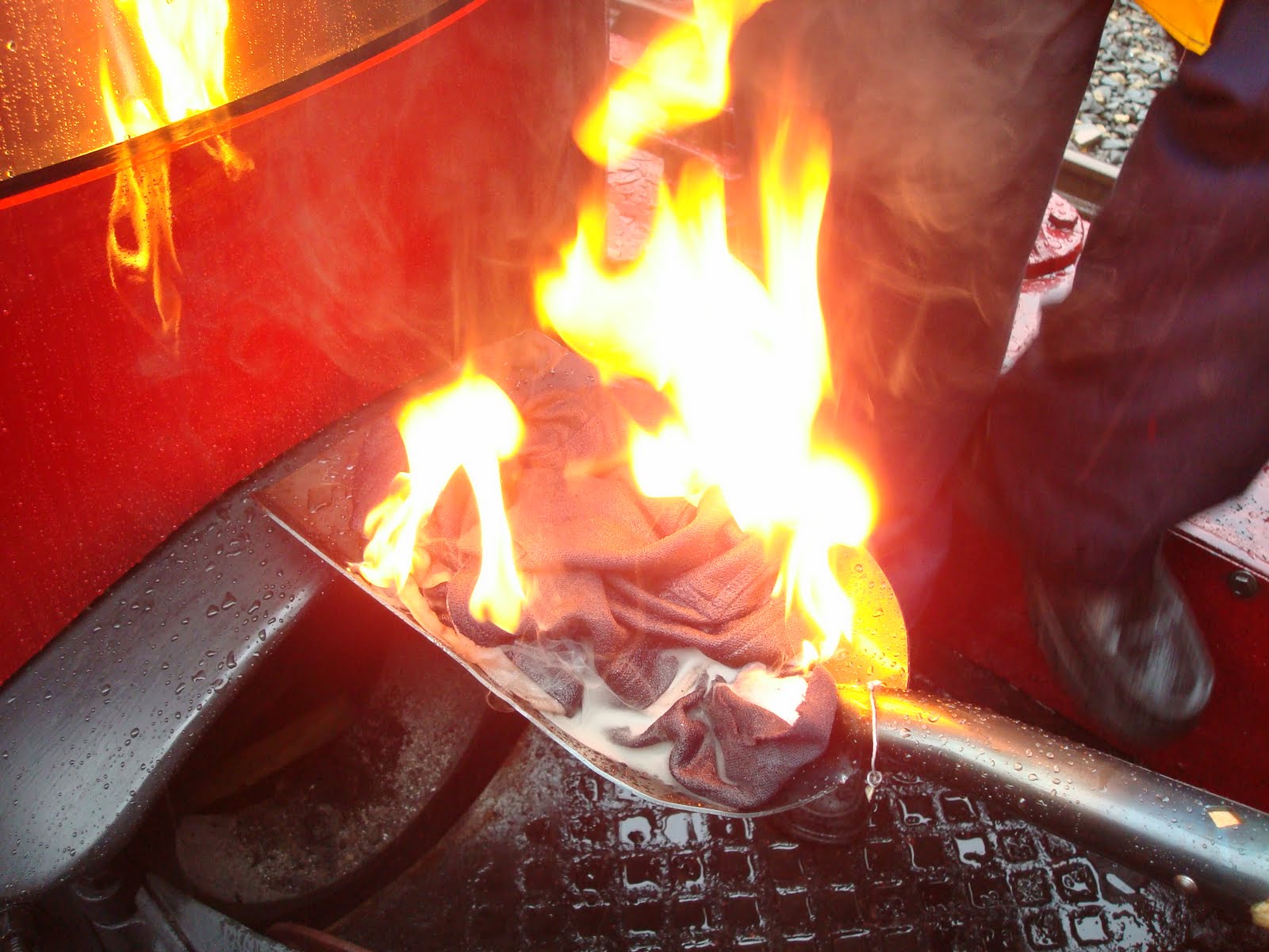
Below: The first fire at Beamish since the early 1990s is lit.
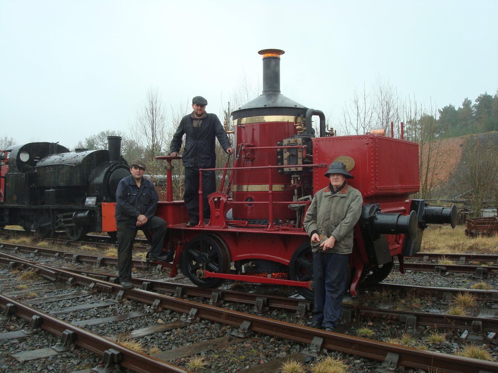
Below: The three restoration protagonists, recreating the original photos taken at Betchworth in the 1870s. Left to right, Vincent Allen, Paul Jarman (the author) and Dave Young.
Here we take our leave, with the working story of Coffee Pot since March 2010 to be concluded in Part 3…


Hi paul,
With the fitting of blind bushes and nordlock washers on coffee pot, how effective are they? Cheers Rob
Hi Rob. They work very effectively and we’ve used the same design of blind bushes on Samson. Paul