
Head Wrightson Coffee Pot No.1 at 150 years old – Part 1…
Part 1: Coffee Pot No.1 1871 – 2004
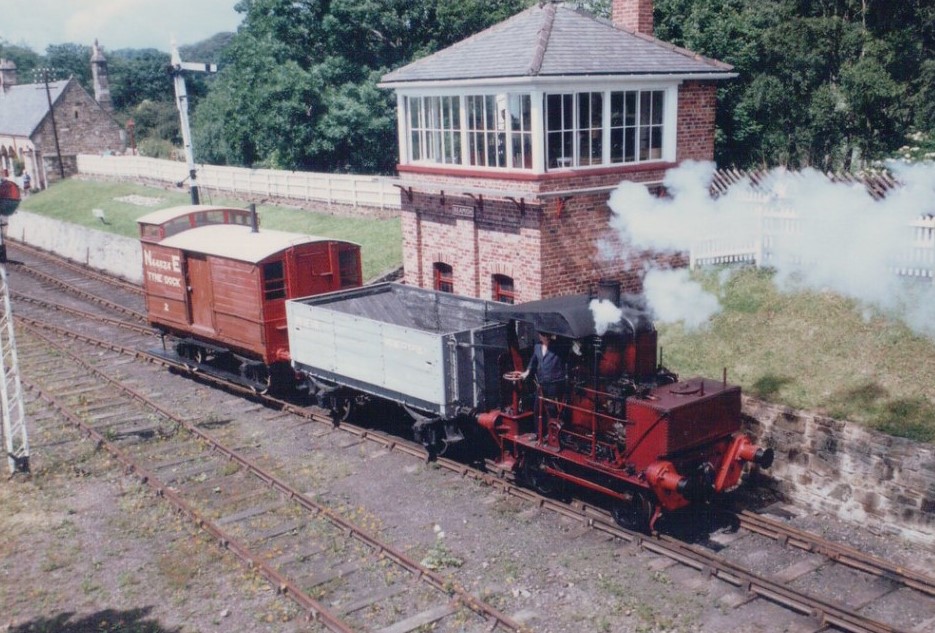
2021 sees the 150th birthday of one of my favourite artefacts at the museum – Head Wrightson steam locomotive, Coffee Pot No.1. All the more pleasing is that for this anniversary, this locomotive is fully operational and, in being so, this makes it one of the oldest working railway steam locomotives in the World, and (I think) the second oldest standard gauge locomotive in the northern hemisphere (Furness Railway No.20 being the oldest and which is nearing the end of an overhaul).
To chronicle Coffee Pot’s life, we will explore the story in three parts, this first instalment looking at the working life and early restorations of the locomotive, taking it to the start of the 2004 rebuild (which included a replacement boiler) and the commencement of its current operational stage of a long working life. We will then look, in detail, at the last restoration in Part 2, followed by a review of the locomotive at work and our experience of it as a historic working object at the museum in Part 3. I will refer to this locomotive as Coffee Pot, as it did not have a works number allocated as far as we can determine (though there would surely have been a number allocated when it was under construction – sadly the Head Wrightson order book for the period the company was building its few locomotives is missing from the records that have largely survived). At Betchworth it seems to have been No.1, but this does not seem to be an official numbering, rather a reflection on it being their first locomotive.
Note: All images are from the Beamish Museum archive, unless otherwise stated.
Introduction
In 1871, T. H. Head engineer of London supplied the Dorking Greystone Lime Company with an 0-4-0 Vertical Boilered Geared locomotive. The diminutive engine was actually built by Head Wrightson & Co Ltd, though worksplates stating this were only carried during its first preservation period (something that we will return to in Part 2).
The origins of this locomotive were in Head Wrightson’s standard ‘Type 1’ design. In reality a standard ‘factory’ locomotive was a rare beast and in this instance two modifications were requested by the Dorking Greystone Company. These were that sprung buffers be fitted in place of the dumb buffered option offered, and that a 300 gallon water tank replace the standard 150 gallon version usually offered. These extras added £10 to the cost of the engine! The little Coffee Pot fulfilled the simple tasks asked of it in the quarry until the early 1950s, when it was withdrawn and left to fall into a derelict condition.
The purchase cost was £462.9.6 plus £9.98 carriage. Payment was arranged in two instalments, on 14/9/1871 Head suggested a payment of £231.4.9. A further payment was made of £262.9.6 (shown in statements for 29/11/1871 and 8/12/1871). Clearly this is an imbalance as the former figure represents one half (including the extra for the water tank), the latter figure suggesting a number of other extras were included. The letter confirming the order refers to numerous tools being requested in order to maintain the locomotive, so perhaps this explains the discrepancy.
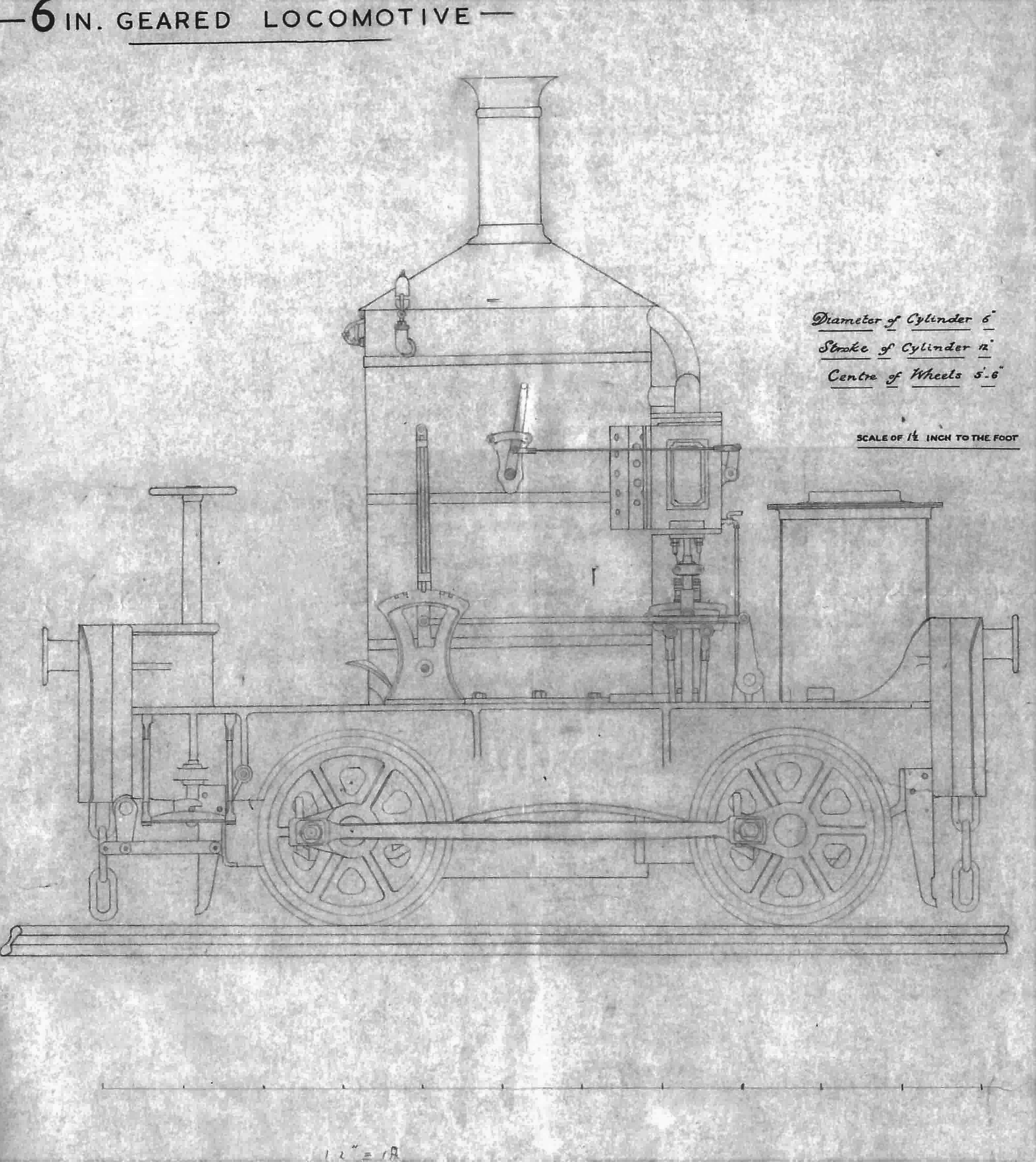
Below: A drawing of the Type 1 design produced by Head Wrightson – note the smaller water tank and absence of large sprung buffers. A different style of reversing lever catch is also evident. The main structural members are the frames, consisting of a one piece casting that incorporates the side plates, buffer beams, bunker and bracing. The hornguides are machined into this and lined. This is a rare example of such a framing on a steam locomotive (particularly in cast iron). In later years US locomotive practice widely employed cast steel frame beds on modern steam locomotives, though was not found commonly in the UK, making this a rare example of the type on British soil and particularly rare to be built by a British manufacturer. Some evidence of dressing is still apparent on the casting, likewise apparent distortion across the diagonal rear RH buffer beam to front LH buffer beam. This is a casting fault and would appear to have caused no operational difficulty for the locomotive at Betchworth or Beamish.
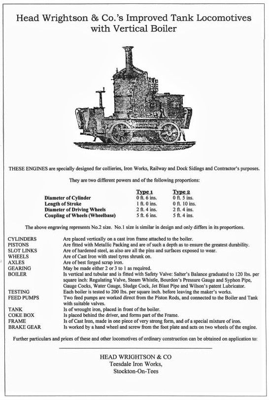
Below: A reproduction of the original specification sheet produced by Head Wrightson for their Type 1 and Type 2 vertical boiler locomotives. A fuller description of Head Wrightson’s locomotive building can be found in the earlier post featuring the 1873 locomotive built by the firm and which also survives at Beamish: http://beamishtransportonline.co.uk/2020/04/shdc-no-17-a-history-and-review/
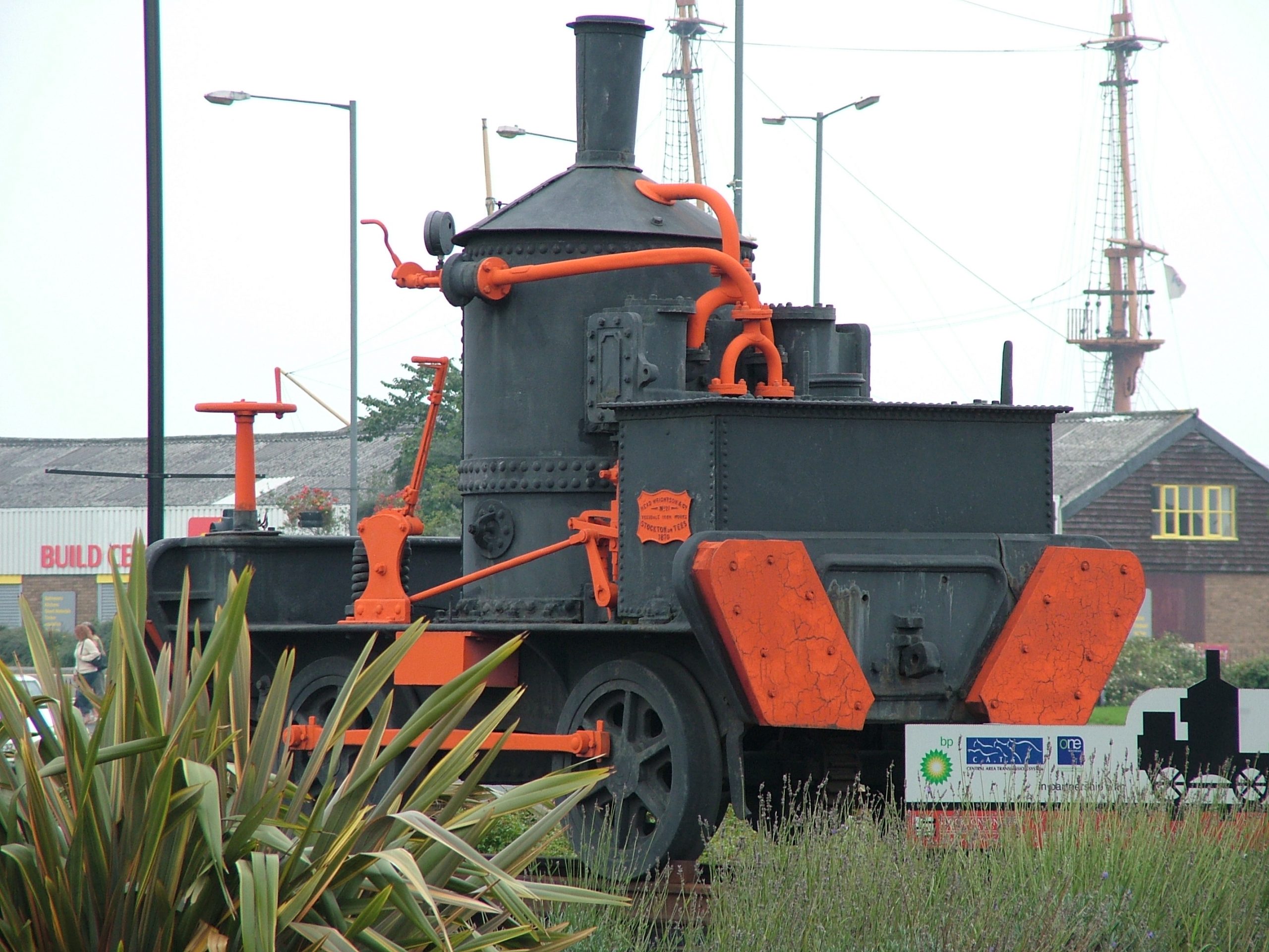
Below: Two views of Seaham Harbour Dock Company No.16 (HW’s number 21 of 1870) showing what a standard Type 1 looked like, sans buffers and with a 150 gallon water tank at the front of the locomotive. Note the coil springs on the footplate – the later locomotives were fitted with leaf springs, located within the cast iron one-piece frame and protected by plating at the footplate end. The regulator arrangement also differed on the 1871 Betchworth locomotive.
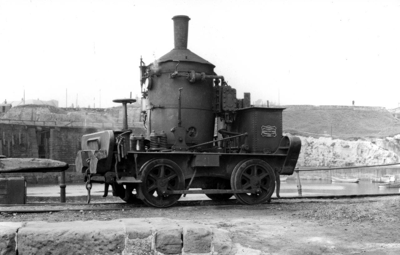
Below: SHDC 16 is preserved at Preston Hall today, but spent a spell of time on a roundabout in Stockton-on-Tees, where this view was taken in the early 2000s. The boiler of this locomotive, that one originally fitted to it when built, was studied in detail to create the drawings needed for Coffee Pot’s new boiler (as we will see in Part 2). Note the crack in the frame above the right hand buffer (as we view it here).
The Betchworth loco…
Some information taken from the original specification and supply sheets for the locomotive:
- The connecting Rods are forked to take cross-head pins and are fitted with brass bearings. The crank pin is 2 1/8″ dia. by 2 1/2″ long and the side rod pins are 2″ dia. by 2 1/4″ long. The Side rods have solid forged ends and brass bearings with adjusting keys.
- The Slot links and also all pins and eyes exposed to much wear are of steel, the links are 1 1/4 inch wide, the pins 1″ dia. and the eyes have large wearing surface.
- The Engine is geared two to one.
- The boiler is supplied with water by one No.4 Giffords Injector.
- The Regulator handle is placed at right hand side
- of boiler, the starting valve being between the Cylinders.
- The Boiler is covered with soft wood, laggings and over this is fixed sheet iron.
- The Engine is furnished with Glass Water gauge, two water cocks, Four mud holes, one blow off cock, one steam whistle, one safety valve and spring balance, a Lubricator for Cylinders, one steam jet cock, Fixing irons & a set of spanners.
- The weight of Locomotive in complete working order is 8 tons 18 cwt.
- The consumption of Coke per day is 4 cwt.
It is interesting to study the above list of extras requested by the Dorking Greystone Lime Company. It clearly reflects that they were previously only experienced in horse operation as they have not even the most elementary tools associated with steam locomotive operation, maintenance and repair (nor, even, oil cans!). It would be very rewarding to recreate the above list for the launch and subsequent operation of the Coffee Pot at Beamish… If only the costs were still at 1871 prices! The usual practice for maintaing water level in the boiler is that two forms of filling the boiler whilst the locomotive is in steam are available (the requirement is actually that you must be able to tell how much water is in the boiler, not how you might add more – the redundancy for safety reasons advocating two separate means of doing this). Normally a pair of injectors are used, as the Coffee Pot later carried, but a supplementary Worthington Simpson steam pump was fitted for a period at Betchworth in order to supplement the Giffard (note spelling varies of Giffard or Gifford) No.4 injector. It is not clear if the weight is that of the modified Coffee Pot or standard Type 1 locomotive. With the later boilers it is quoted at 11 tons 11 cwt.
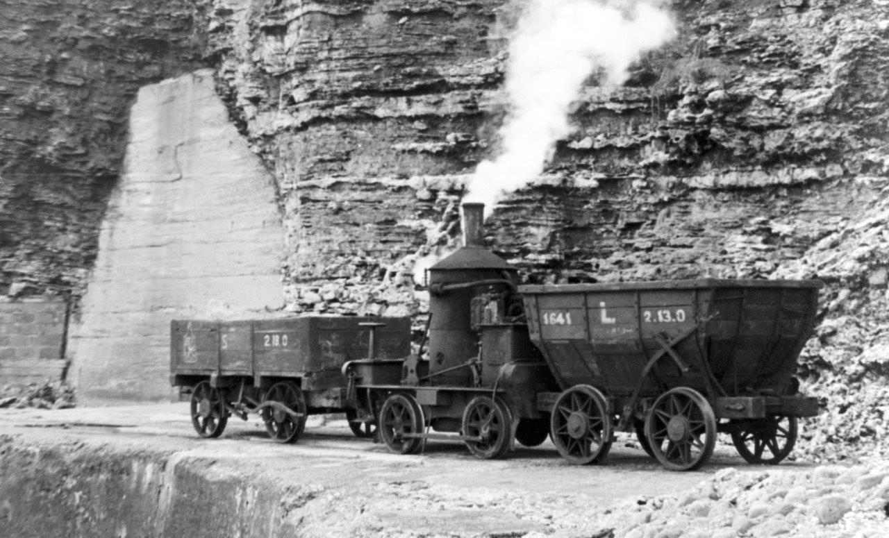
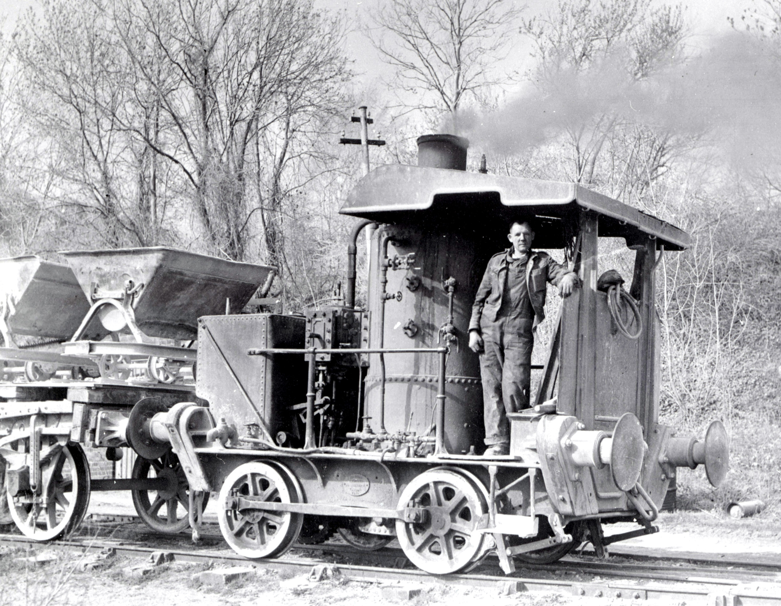
Below: The oldest known image of the Betchworth Coffee Pot – probably shortly after arrival at Betchworth (and before the fitting of the handrails along the running plate). Note the larger water tank and heavy-duty sprung buffers when compared to the drawing above and the appearance of SHDC 16. This image also provided sufficient information to replicate the wooden toolbox that sits atop the bunker in this view. Of note is the injector on the side of the boiler, with steam taken from the steam space in the barrel, into the injector and delivered to a position low down (just above the footplate) on the same.
The water delivery pipe from the water tank can clearly be seen. Also clearly visible are the two try-cocks and unprotected gauge glass – giving two means of ascertaining the water level in the boiler. The pressure gauge is fed from a union on the base of the safety valve casting (the gauge being the white-faced circular object, the safety valve the grey shape above), whilst the safety valve spring is contained within the brass tube to the right of the gauge. Further to the right is the whistle, visible above the driver’s arm.
The cylinders (a pair) are mounted on a steel plate affixed to the boiler vertically and driving a crankshaft (itself boiler mounted). A sliding pinion enables the engine unit to run whilst the locomotive remains static, the disengaging lever being operated to link the pinion drive with an axle mounted gear at a ratio of 3:1 (originally 2:1). This would seem to be a later addition, perhaps to enable the locomotive to coast from the quarry to the exchange sidings at Betchworth station without unduly stressing the pistons and valve gear which would be being driven at quite a rate when coasting (and offer little braking resistance as the locomotive is suprisinglg good at stopping on its handbrake and the trains it hauled to the station would be short and capable of being braked as well).
The pistons drive on to the rear crank axle, and the integral cranks on the driving wheels on each side are mechanically linked by a coupling rod. This the loco’s classification is an 0-4-0VBGT (four coupled wheels, vertical boiler, geared drive and a tank mounted onto the footplate or frames). The Stephenson valve gear is controlled by a reversing quadrant set on the right hand side of the footplate. The cylinder drain cocks are operated by a lever, which is also set in the right hand side of the cab. Tail rods were added to the locomotive, there being no slide bars (presumably the tail rods were to lessen wear caused by unequal thrusting of the piston).

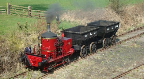
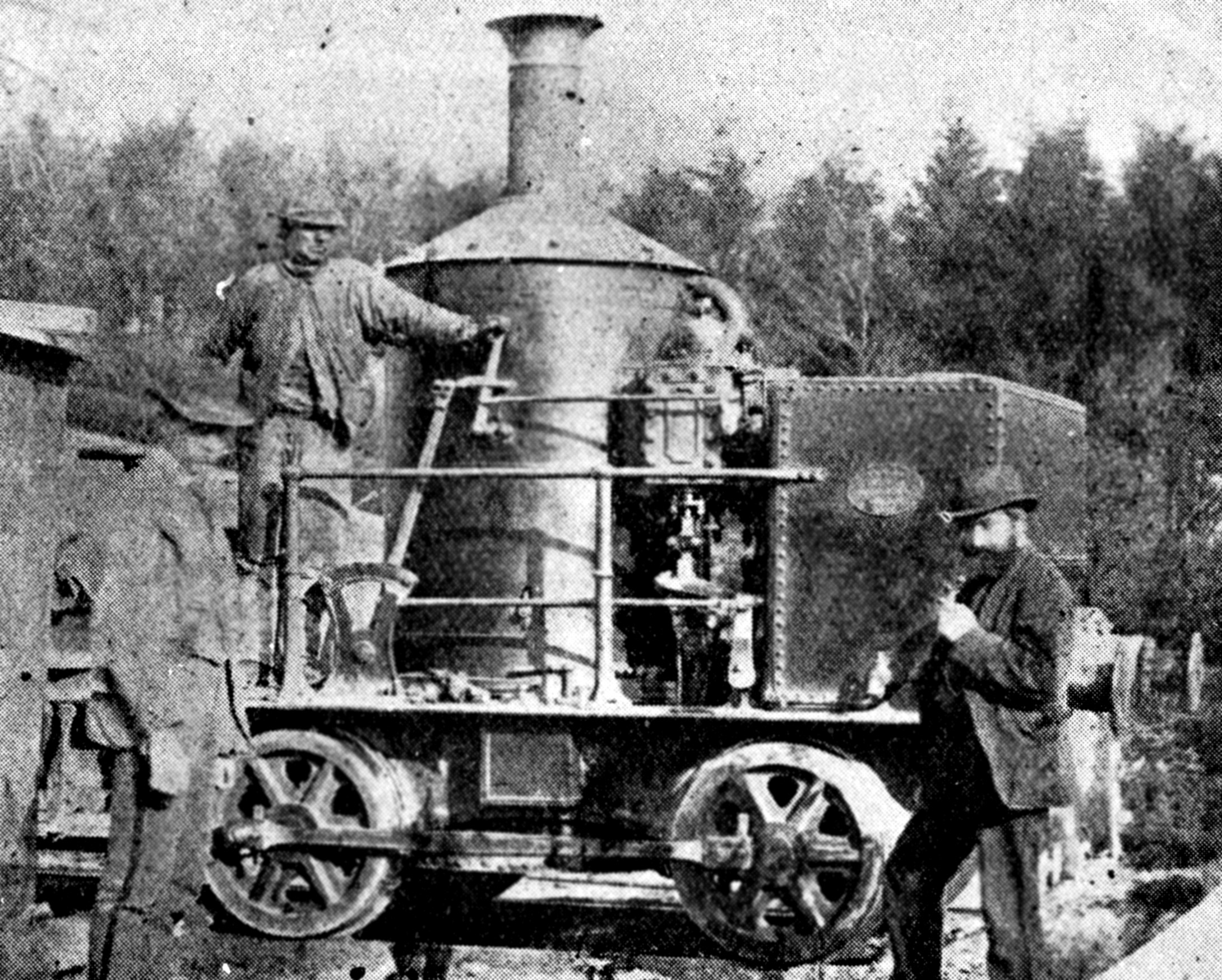
Below: At an unknown date between 1871 and 1879 handrails were fitted to the side of the locomotive, presumably to allow safe passage by the crew to the front end for lubrication purposes and access to the cylinders. This view also clearly shows what we have assumed to be a sandbox, located between the driving wheels, beneath the running plate with what looks like an operating handle above the running plate – the holes on the locomotive still exist. The driving wheel centre castings are very distinct on all of the HW locomotives, being heavily webbed rather than simply open spoked. We return to these later on…
Water is stored in a 300 gallon tank mounted at the front of the engine, which is filled from the top of the tank. Water is passed from the tank into the boiler by two steam injectors (originally one Giffard No.4 and later supplemented by a Worthington steam pump, though this was short lived), mounted one on each side of the boiler. The later compliment of injectors included a Smiths example and an unknown type with sliding cone adjustment. These are now in store as a pump was fitted to the locomotive at the last restoration.
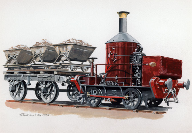
Below: Artist Jonathan Clay produced this painting of Coffee Pot for us in 2006, complete with one of the transporter waggons used at Betchworth to move the two-foot gauge skip waggons around the quarry (something replicated at Beamish in recent years). (Reproduced courtesy of Jonathan Clay)
Coffee Pot’s boiler sagas…
During the summer of 1873 a replacement boiler was fitted. Built by Davey Paxman Ltd of Colchester (and possibly supplied by Townshend, Hook and Company of Snodland Works) it was believed to be less prone to leakage than the Head Wrightson boiler.
The original was a 3’6″ diameter with 36 2″ wrought iron tubes. A letter of the 7/7/1873 to Hughes of Loughborough referred to the boiler as being 3′ 6 1/2″ in diameter and 7′ 6″ tall. A letter dated 20/1/1873 to Davy Paxman authorised the construction of a new multi-tubular boiler at a cost of £140. Several letters exist urging the rapid completion of this work, until one on the 25/3/1873 states: “As I anticipated our engine broke down this afternoon. The tubes leaked andput the fire out. I hope thatyou are making a first classjob of it and that I may hearfrom you to ? offat once as I really don ‘t know what I am to do now, as we can not buy or hire horses at so short a notice. Please don ‘t loose a moment in completing it and sending it offwhen ready”. The boiler had arrived by 30/5/1873 and was being fitted shortly afterwards.
It has also been stated that due to the severe gradients at Betchworth, the original and shorter boiler struggled to maintain either a satisfactory water level over the firebox crown or steam pressure for operation. Experience of operating Coffee Pot since 2010 suggests there are no such problems to overcome, the boiler being very forgiving of varying water levels. However, working in a lime quarry would tend to indicate that the water supply was anything but pure, so scaling (and subseqwuent leaking) would be a very real risk and challenge to manage.
At some time prior to 1879 the first of two boilers of the ‘Hanging Tube’ variety was fitted. Supplied by Lewis Olrick & Co. of Manchester, the boiler featured 37 (though some sources state 52) hanging water tubes of Field’s design (patented in 1862 by E. Field and Messrs Merryweather and Company and consisting of vertical tubes with closed ends hanging into the fire box. Within these smaller tubes were fitted, down which cool heavy water flowed until reaching the heat of the firebox where it returned in the annular space between the two tubes so creating a current of water within the boiler). The boilers were 4′ 2″ diameter and had a centre flue.
A letter to Mr L Olrick on 17/6/1879 indicated great satisfaction with the boiler supplied ‘for no tubes have leaked or been renewed. We use chalk water purified on Dr Clerk’s principal. Its steaming qualities are far superior to the Paxman (?) one we had previously and with less coal although I cannot say how much as we have not weighed it. Its first cost was 30 percent less than that named which was constantly requiring repairs”.
Specification dated 26th November 1879 (only eight years after construction, apparently for the third boiler fitted, though documentary evidence would imply that it was already carried by this date — was this for a fourth boiler not immediately supplied, or for a boiler fitted to other steam plant at Betchworth? A letter dated 17/6/1879 praises the Olrick boiler fitted, whence the apparent inconsistency in dates — unless this was the a fourth boiler and that the Coffee Pot was actually fitted with five boilers whilst at Betchworth?):
- Height: 9ft 10ins.
- Diameter: 4ft 2 ins (3 ft 6ins. on original)
- Lowmoor Iron with shellplates double riveted on vertical seams.
- Boiler stayed with six vertical 1 1/4 in. stays between tubeplates, firebox stayed with 44 horizontal Lowmoor iron stays screwed through shell and firebox plates and riveted over.
- One man-hole door, four mud-doors, wrought iron furnace door and cast iron firebars.
- Test pressure 225psi (200psi on original)
Below is the original letter of specification from Lewis Olrick to Betchworth regarding their request for a 151-1P rated vertical boiler, apparently for the Coffee Pot. However, as seen earlier, the dates for this specification do not quite tally with those for the supply of a new boilers for this locomotive. Dated 26/11/1879.
SPECIFICATION OF A 15 HP FIELD BOILER
The boiler will be 9ft IOins in height & 4ft 2ins external diameter. The top-plate 11/16″; the uptakeplate 7/16″; shellplates to be of Bloomfield Iron, or iron of equally good quality. The tubeplate 13/16″ & the firebox plates 3/8 ” thick, to be of Best Low Moor iron. The shellplates to be double riveted in the vertical seams. The boiler to be stayed with 6 vertical 1 1/4 ” stays between tubeplate & top-plate.
The firebox to be stayed with 44 horizontal Low Moor stays screwed through both shell & firebox plates & riveted over at the ends. The boiler to be supplied with I manhole door, 4 mudhole doors, a wrought iron furnace door, & a complete set of cast iron firebars. The boiler to be made for a working pressure of 150 lbs, & to be tested to an hydraulic pressure of225 lbs. All materials & workmanship to be of the best description.
Coffee Pot No. 1 ‘s luck with boiler longevity was yet again lacking, as on the 12/11/1879 a request was made to Lewis Olrick & Co for a 15HP boiler. A reply was received dated 26/11/1879. The comment was added that no new fittings would be required as the existing ones were still serviceable from the existing boiler. Was this for Coffee Pot? Was the replacement already found wanting? Boiler records from 1915 indicate the boiler as being 5/127403 (though this may have been an administration number), built by W.N.Nicholson & Sons Ltd, Newark, for Lewis Olrick in 1904. A summary at present of the boilers might suggest:
- 1871 – Head Wrightson boiler
- 1873 – David Paxman boiler fitted
- 1879 – Lewis Olrick boiler fitted (date not confirmed)
- 1904 – Lewis Olrick boiler fitted
- 2007 – Israel Netwon & Sons boiler built and fitted
The taller boilers fitted may have caused operational difficulties for a cab was in place by 1929 that was strongly supported in such a was as to brace the boiler top against upright pillars from the rear buffer beam.. These were removed during the 1960 restoration by Head Wrightson but (replicas) reinstated during the 1984 overhaul. These items are now in store at Beamish.
1920s rebuild…
Below: By the time the fourth boiler was fitted, the locomotive as looking rather different… Note the arrangement of injectors on the side of the boiler and the industrial safety valve on top of it. The cab is formed of the heavy structure that seems to be to prevent the boiler from wobbling (remeber that it is taller than the origianl design, and has the cylinders mounted on it). The structure is just visible in this image. The cab roof itself is plate, designed to provide shelter (but little else!) from the elements.
Study of photographs reveals that initially six spoke wheels were fitted to Coffee Pot. In this 1929 photograph a five spoke pattern is apparent. However by 1948 six spokes are apparent again! There are obscure references to wheel bosses and supply of new centres; however no dates have yet been verified. Is it possible that the original wheels cracked or wore (particularly flanges) so an alternative set were obtained to enable direct replacement in order to keep the locomotive in operation. When these became worn maybe the originals were re-tyred and replaced, so retaining the 1871 bosses upon withdrawal.

Below: In 1938 we still see five spokes… Note the enclosure of the steam pipes above the cylinders (probably an effort to insulate them), and the coal piled agains the backsheet of the cab.

Below: A view of Coffee Pot at Betchworth, complete with roof and the substantial bracing that created a rigid square between the boiler, backsheet, roof supports (not visible here) and footplate. Note too the diagonal brace for the water tank and also a return to six spoke wheels!
Into preservation… Phase 1
Below: It is believed that the Coffee Pot last worked at Betchworth in 1949, though some sources indicate an overhaul in 1952. The latter seems unlikely as photographic evidence suggests it was derelict shortly after this date. It was, however, examined in steam on 2/5/1950 so this may well have been its last year of operation (if this was a boiler inspection it may have run into 1951). September 1960 saw the Coffee Pot return to Teesside having been sold by Dorking to Head Wrightson who wished to display the locomotive at their Thornaby works (alongside their works No.21 of 1870 that had worked at Seaham Harbour, seen earlier). The apprentice school at Head Wrightson rapidly dismantled the locomotive and commenced a cosmetic restoration to an approximation of the 1871 as-built condition. This included fitting air pipes to enable it to be demonstrated to interested visitors. A report of this restoration is kept on the file.
Some interesting photos of the three vertical boilered locomotives preserved by the firm can be found here:
Coffee Pot Locomotives, Thornaby
1800s Works Locomotive and Trucks c1959
https://heritage.stockton.gov.uk/resources/head-wrightson/gallery/b2_hd-wrightson_031-1/
https://heritage.stockton.gov.uk/resources/head-wrightson/gallery/b2_hd-wrightson_030-1/
https://heritage.stockton.gov.uk/resources/head-wrightson/gallery/b2_hd-wrightson_001-1/
(use the next/previous function to view other images including No.17 under restoration).
Below: In August 1962 John Wrightson offered Frank Atkinson ‘one of the three Coffee Pot locomotives for the proposed North East folk museum, mentioning the1871 built locomotive specifically. On August 13th this offer was accepted though it wasn’t formally completed until the Summer of 1969 when Head Wrightson had finally to insist that the locomotive be collected. It was moved to Consett Ironworks for initial storage in July 1970. It moved to Marley Hill engine shed (now home of the Tanfield Railway) in September 1971, before finally moving to Beamish in March 1975. These two views show Coffee Pot at Marley Hill, with the still-active colliery visible in the background. The paint colours would seem to be conjectural, though were certainly startling!
Below: In 1971 Coffee Pot moved to Seaham Harbour, where it took part in filming work for a television documentary called The Ascent of Man. Here it was coupled to a chaldron waggon, which carried a compressor in order to enable the locomotive to make limited movements running on air. Former museum employee, Alan Grimes, recalled that the air supply was insufficient for operation, but did enable the whislte to be blown, whilst most propulsion was actually supplied by one of the Dock Company diesel shunters! It is this visit that makes the answer to the not uncommon question “Is this the one that worked at Seaham?” hard to answer without a longer than usual explanation!

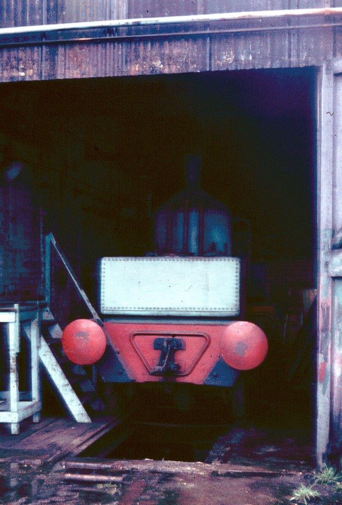
Below: A rather interesting view taken in March 1975 after Coffee Pot arrived at Beamish, and showing it inside the shed prepared for the replica Locomotion No.1 and which, in a ruinous state, still remains in the Colliery area today. (Photo embedded from the Flickr page of David Shevels – click the image to take you to the applicable page which also includes a number of other 1975 views of the museum)

Preservation – Phase 2…
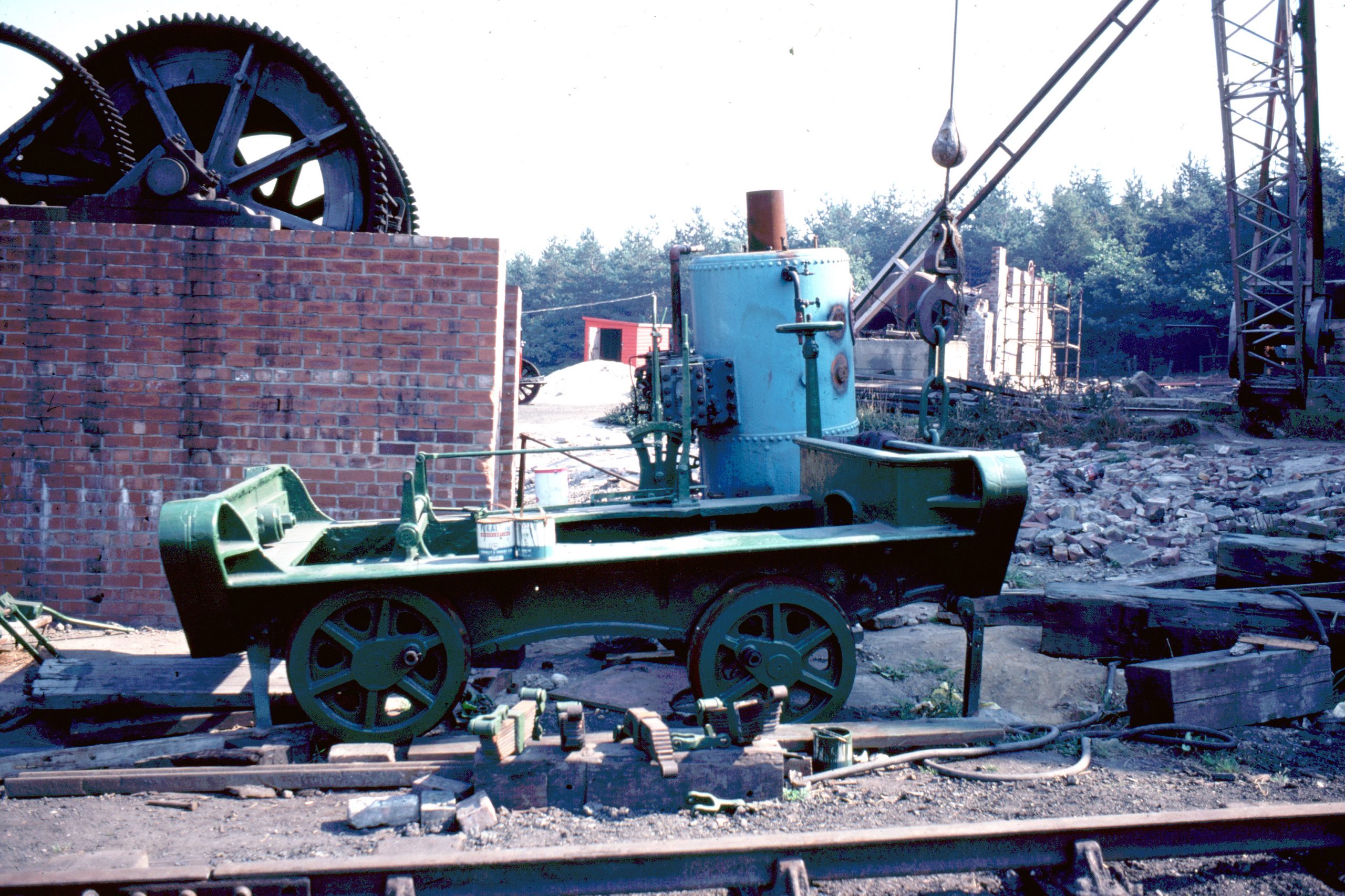
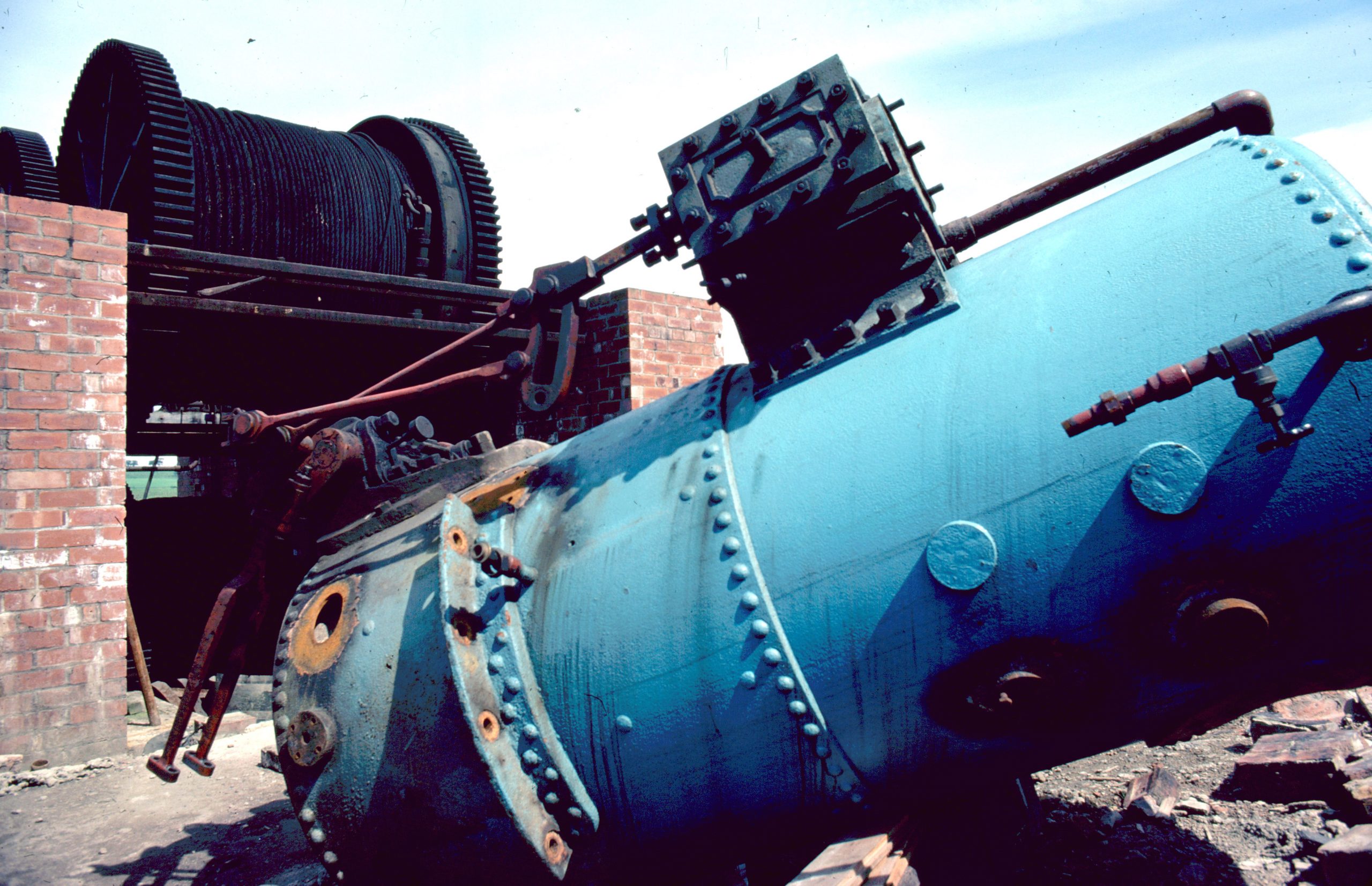
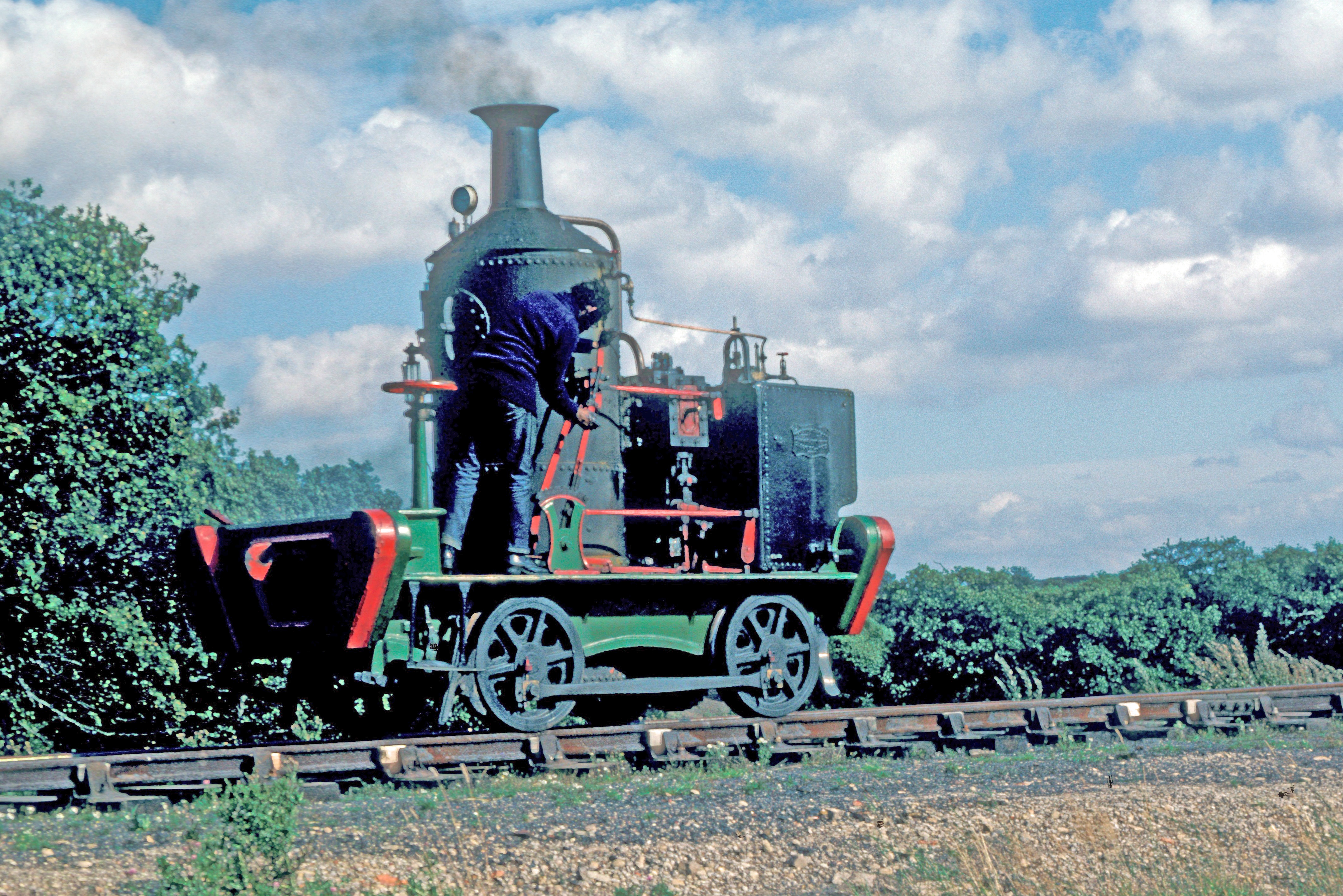
Below: Once at Beamish steps were taken to return the Coffee Pot to steaming condition , and a number of appearances were made in action (wearing a livery of black boiler and green frames). These views show the work underway, including a repaint into green and black livery. The location is adjacent to the Silksworth Sinking Engine, on the present site of the Colliery screens and winding house.
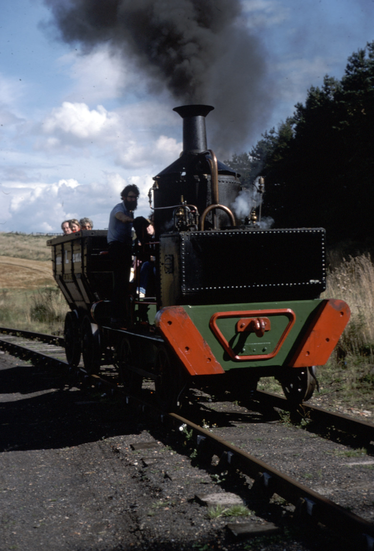
Below: Once returned to steam, a number of working appearances were made on the demonstration running line at Rowley Station. Passenger trains (with the exception of some evening specials for the Beamish Development Trust in the late 70s and early 80s) were limited to what is the current limit of running, though as can be seen here, rides in chaldron waggons (!) clearly exceeded the limit of running and reached the Colliery area itself.
Below: The locomotive is seen rounding the curve which was later removed and replaced with the site of the Pockerley tramstop, and now the current limit of the narrow gauge running line.
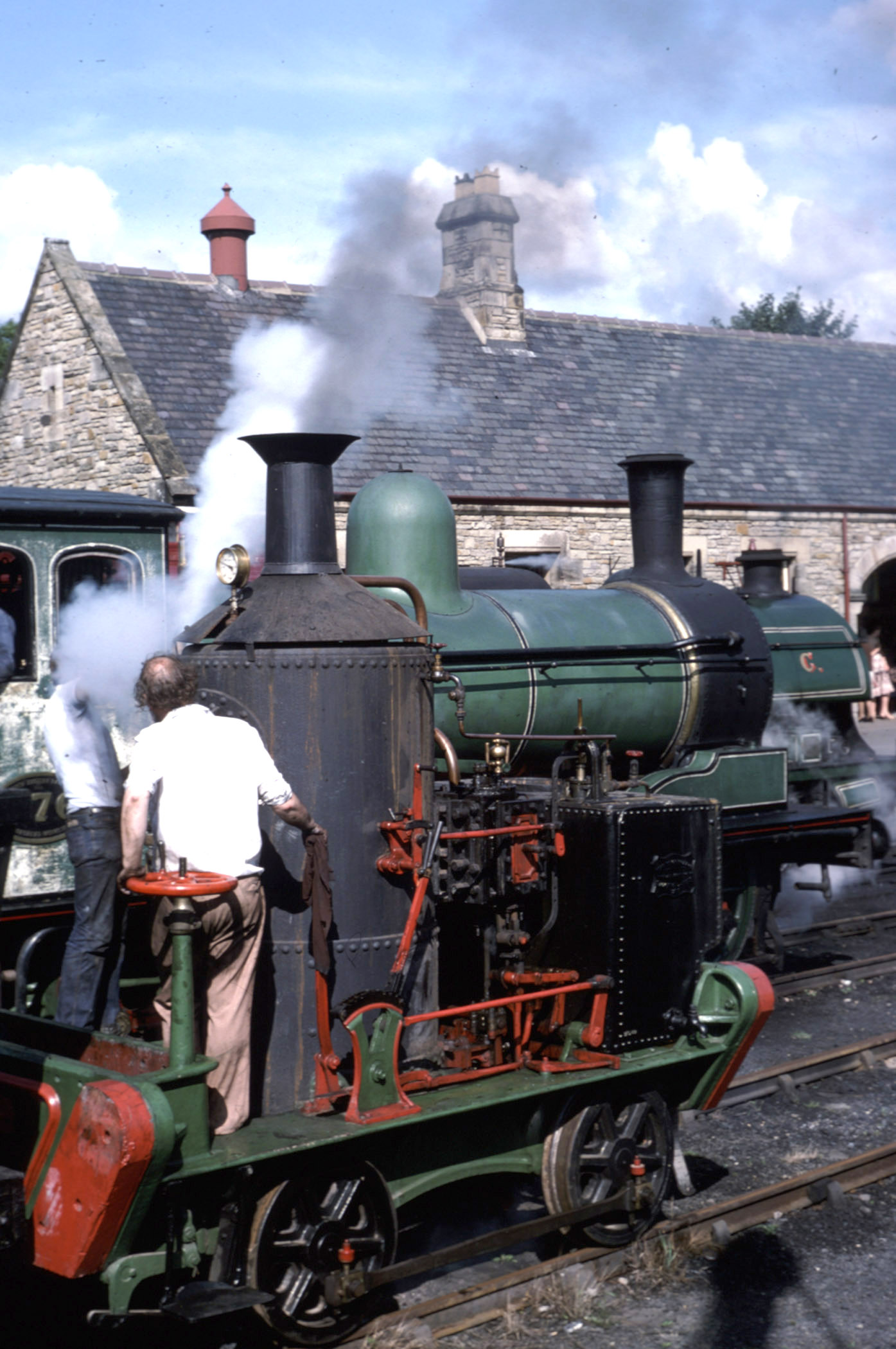
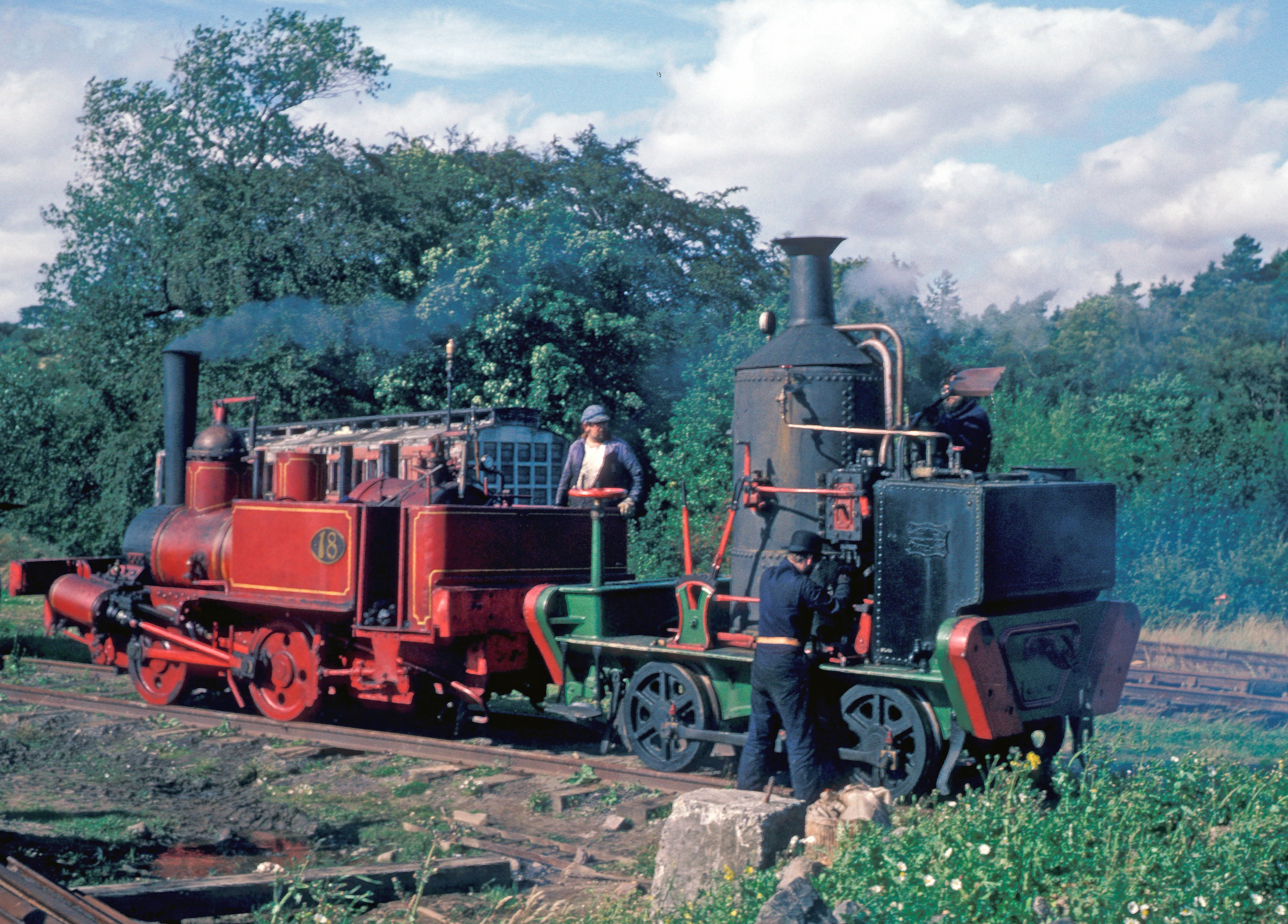
Below: We ought to take this view again! No.18 plus No.1, both in steam behind the Town. I am told they had to share some components, such as cylinder lubricators, so this may be quite a rare view. Both look substantially different now of course, and are perhaps rather better representative of their own history than their late 1970s guise suggested! (Photos courtesy of Brian Tunnard See: http://beamishtransportonline.co.uk/2015/02/early-days-at-beamish/ )
Preservation – Phase 3…
In the period 1983 to 1984 the locomotive was overhauled by apprentices on a Manpower Training Scheme at ICI Wilton, appropriately on Teesside where the Coffee Pot was originally built. This included remaking the cab structure and returning the Coffee Pot to the 1920s/30s appearance. Resplendent in a new livery of maroon (as there was no indication of what the Betchworth livery was, other than white lime dust!), the rebuilt locomotive was launched at Beamish on May 31st 1984. The work included remaking the cab structure and returning the Coffee Pot to the 1920s/30s appearance. It was formally launched into traffic at Beamish on 31 st May 1984.
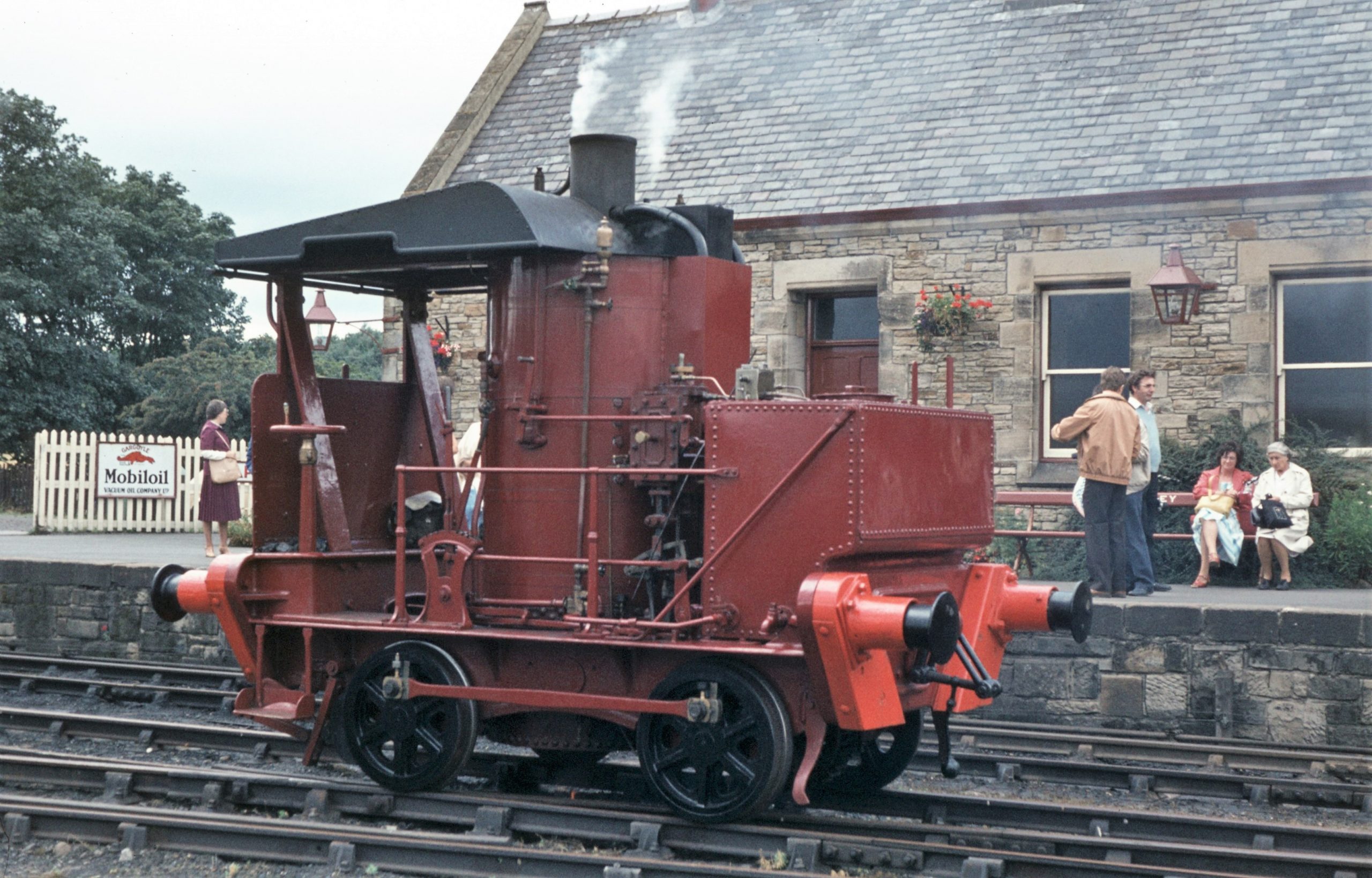
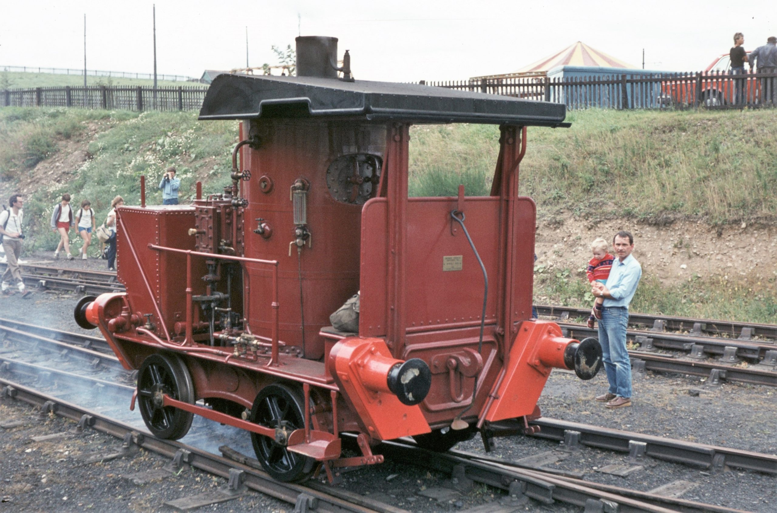
Below: Two photos of Coffee Pot taken in September 1984, fresh from overhaul at ICI Wilton. Note the rather more relaxed approach to visitors standing on running lines than we would permit these days! (Photos courtesy of Nigel Menzies)
Below: This view, taken on the 28th June 1990, may well be one of the last steamings of Coffee Pot at Beamish in it’s 1980s guise. Whilst a final steaming date has always been elusive, its relocation to the Colliery area would appear to have been by road, when the NER branchline was bisected in order to create the full tramway circle. There are some images showing it at work in the Colliery, with an incomplete cab structure, so it is perhaps possible that it ran into the very early 1990s – records to confirm this (or otherwise) have been evasive thus far. (Photo courtesy of Mark Sampson)
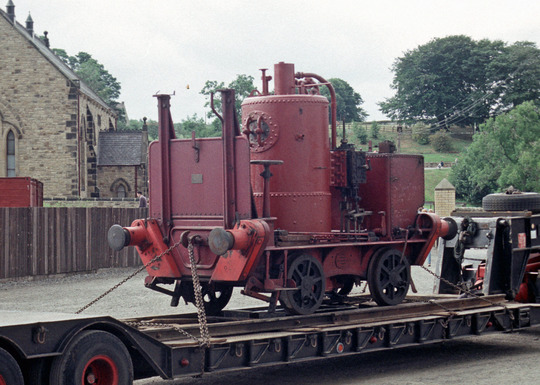
Below: An undated view from the files showing Coffee Pot in the Colliery Yard aboard Dave Antell’s low-loader. This shows that there has been dismantling and some reassembly, including repainting the boiler barrel. The locomotive was steamed again after this image was taken, and prints of this exist on the file, albeit not dated.
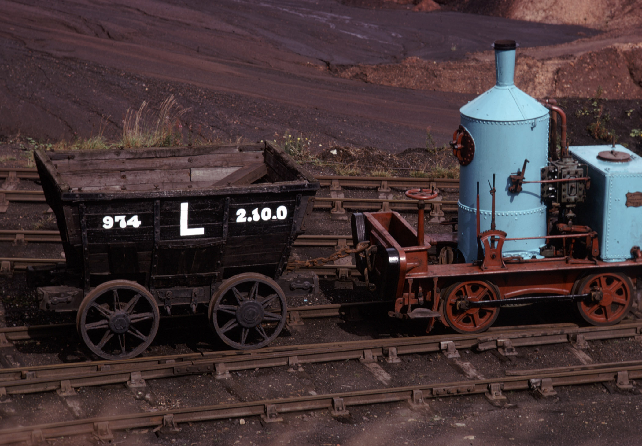
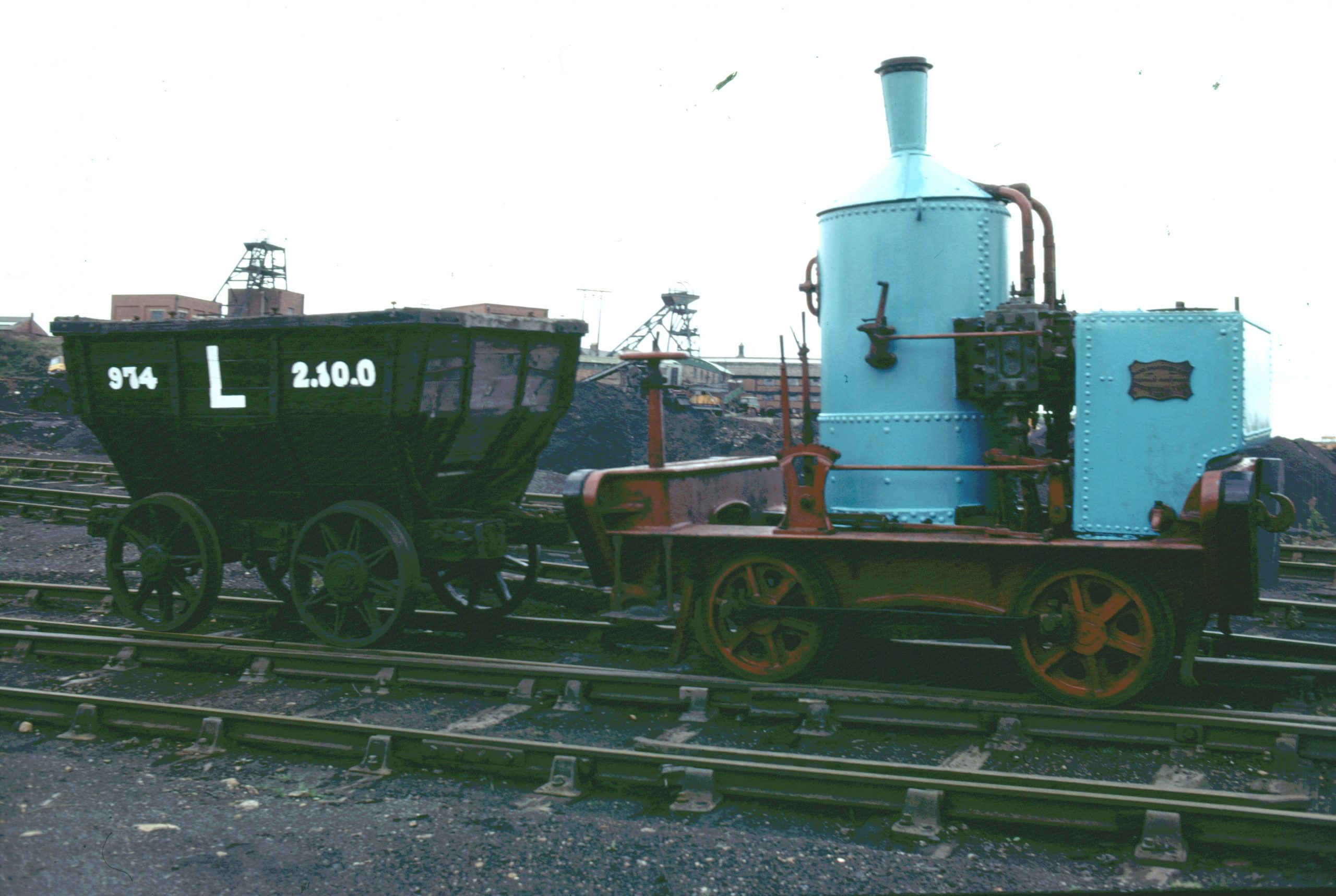
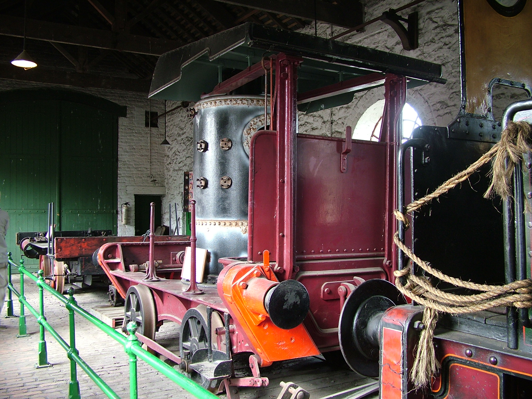
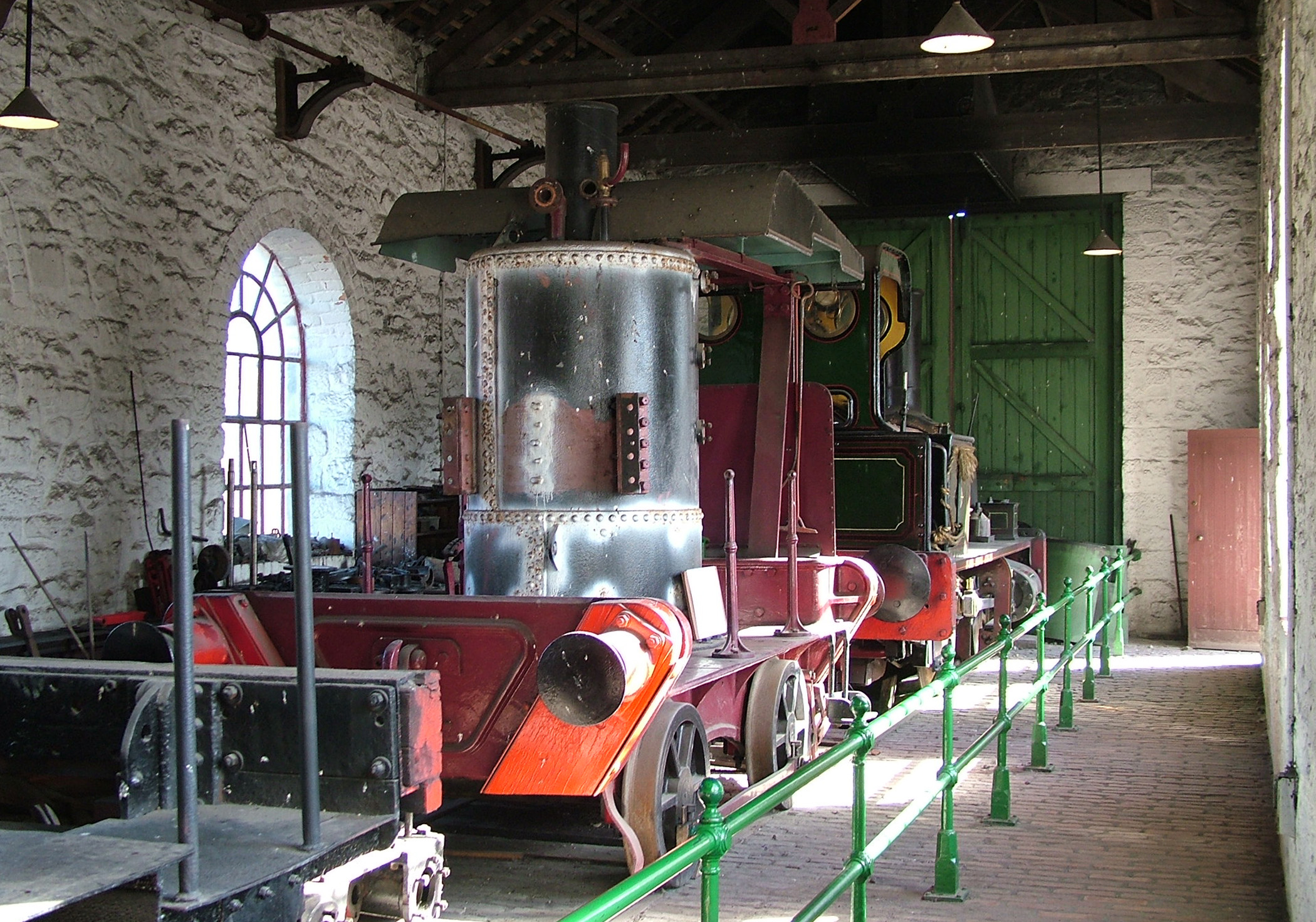
Below: Coffee Pot after many years out of use, seen in 2005, as a start of its restoration was being considered. Note the white spray on the boiler shell (now painted black), indicating MPI (Magnetic Particle Inspection) of the boiler shell – work that was carried out in 1996, being followed up with an ultrasonic examination of the boiler shell in 1998, with a view to restoring the locomotive to operation. The 1996 work included installation of blind bushes, to solve the problems of steam leakage on the studs holding the cylinder and crankshaft brackets to the boiler. This work was approved and carried out, and proved to be a benchmark for the museum’s Steam Elephant boiler design and later, Coffee Pot’s new 2009 boiler, where blind bushes were incorporated into both vessels. The new-build Samson also incorporates the same design. The blind bush is essentially a socket, welded into the shell and enabling bolts to be inserted, without having to then try to caulk them to create a steam tight joint.
Much of the information here has been gleaned from the locomotive’s museum file, the Beamish photo archive, information that was supplied by Head Wrightson in 1975 and research carried out by John Townsend into the Dorking Greystone Lime Company (who was able to furnish us with considerable information on the second, third and fourth boilers carried, as described above).
You can read about another Head Wrightson locomotive here: http://beamishtransportonline.co.uk/2020/04/shdc-no-17-a-history-and-review/
Here we leave the story for now, which will be continued in Part 2 next week…


Hi paul
Can you upload the photos of her working in the colliery please?
Great history of her and like you im struggling to find her last steam date,
Look forward to part 2
Cheers
Rob
Hi Rob – photos of the loco at work in the Colliery will appear in Part 3 which looks at the restored loco at work. Best wishes, Paul
Worthy of an Industrial Railway Society’s ‘Record’ article! Looking forward to the second installment.
My opinion on this, concerns a wagon with three skips as per the painting to go with the loco, i am not sure if the Amberley Museum saved such an item, but a close replica is a very possible idea, given the wagon was an ex BR underframe, adapted and three skips from the hundreds that survive, i am sure could surely be found, restored and used on this carrier wagon, the fact that it is a carrier wagon, brings another slant to the story, for i do not think, there is such a wagon surviving that can be used of the carrier types in preservation, hence another Northern First.
Fantastic article, i take my hat off to you, no kidding now.
Andrew Waldron.
Hi Andrew – we have built a replica of the transporter waggon – which will be covered in Part 3 but was reported on the blog here:
http://beamishtransportonline.co.uk/2019/04/ti-news-9-2019/
Skips are not as easy to find as you would think, as anyone with them wants to keep them! The majority are the ubiquitous Hudson Rugga type, which would be incorrect for Betchworth. We have two of the more appropriate pattern already and I continue to look out for a third, though they are also pretty handy on the railway vs being on a transpoter waggon! We did load this with the water waggon and coal tubs to support the 15″ gauge operation at the 2019 steam fair, and this can be seen in various photos of the event.
Best wishes
Paul
Great read Paul. The Coffee Pot is a fascinating machine, the most bonkers Loco I’ve ever been lucky enough to work on and thanks to Beamish for keeping it in running order.
Regarding photos of Coffee Pot and No 18 together. I took a photo of the pair at the Great War Steam Fair in 2018. https://flic.kr/p/23ifgcU
Looking forward to part two.
Andrew / Panda
Cheers Andrew! A cracking photo there… Part 2 will be restoration, whilst Part 3 will be the revived loco taking on the World! So plenty of photos of it at work in that one… best wishes, Paul
this makes me wonder, what happened to No 1’s cab?
Hi paul,
Regarding coffee pot last steaming, last week i was in hay on wye and in a book shop reading the railways restored 1995/1996 and it says coffee pot was in working order then, so maybe she was steamed then,
hope this helps
Cheers
Rob