
T&I News 30 2022…
Welcome to what is the last news update for 2022. I’m aiming to produce a review of the year, plus look forward to 2023 before too long, but meanwhile, here are some of the ongoing development with transport and engineering projects here at the (very cold!) museum.
Kerr Stuart 721
Below: The overhaul of this 1901-built gas works locomotive continues, largely utilising the volunteer labour of David Young for the current mechanical progress, and the boiler-making skills of John Fowler Ltd in Cumbria for the overhaul of the boiler.
One of the many areas requiring remedial work are the valve faces, which are worn and require facing back to a flat surface. This is not entirely straightforward, given their location within the valve chest, atop the cylinders and bolted to the frames through the water tank. We are exploring options for carrying out the work on these at the moment. It was the similar experience with No.18 (which David largely repaired by hand and power-drill) that led to Samson having a lamination of valve chest components to enable the easy removal of the valve face and re-machining it flat, when that day comes.
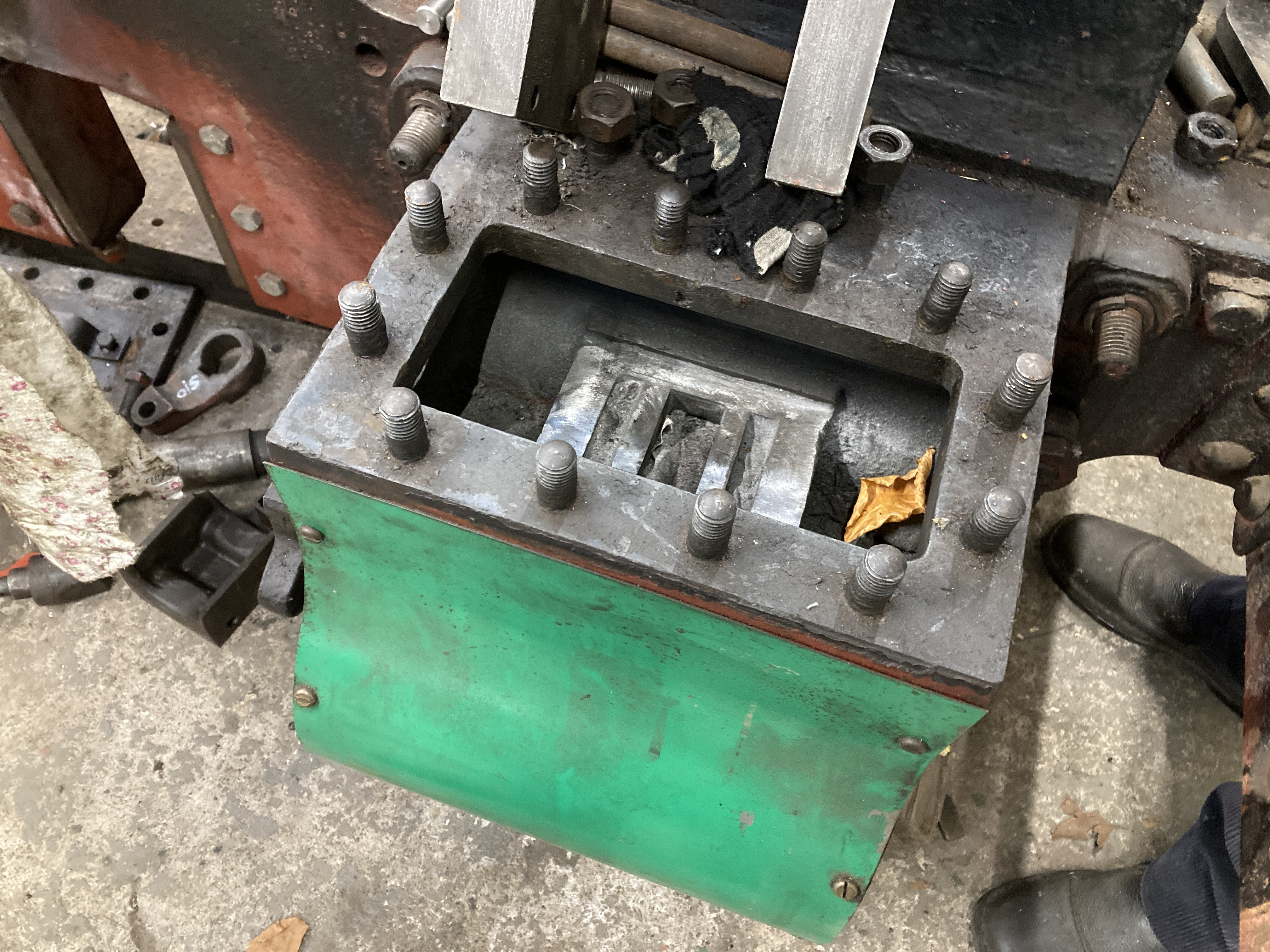
Below: It is fair to say that 721 is a very tired locomotive! There is virtually nothing straight or consistent in dimensional terms, and it has had some remedial works carried out as part of its cosmetic restoration in the past, that will have to be re-done in order for it to be a reliable operating locomotive. In particular, the hornguides were replaced, and these will now have to be matched to axleboxes (with new underkeeps) and then reattached to the frames using fitted bolts to ensure they do not move. As can be seen below, there have been substantial weld repairs in the past too, and these may also account for some of the distortion in the frames. In many ways, it would be easier to replace the frame plates, but as this is a restoration not replication, we won’t be doing that!
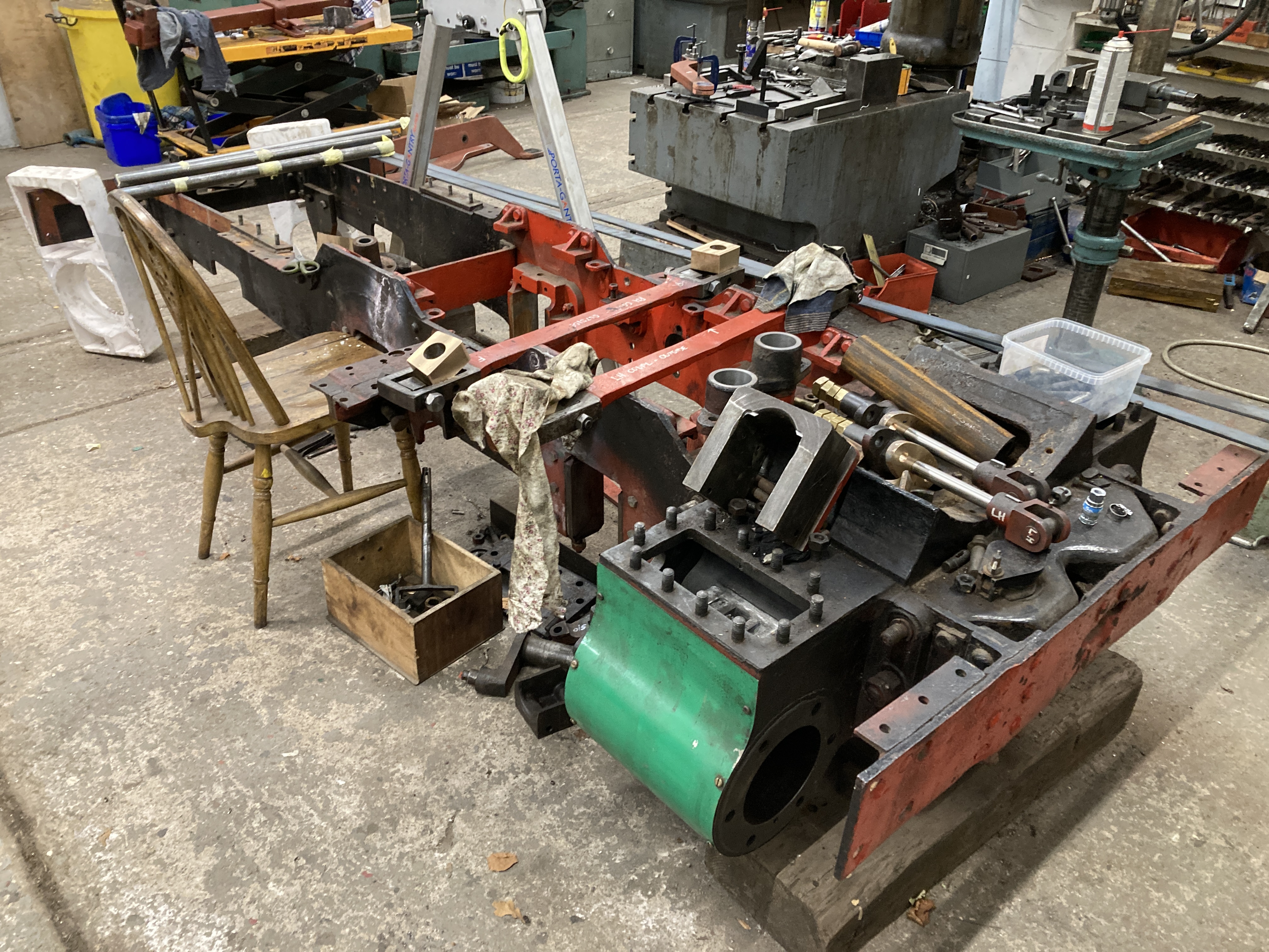
Below: David has bored out the valve rod crank guides (which impart the inside motion to the outside valve chests – normally the valve chests would be between the frames, but on 721 the space is occupied by the water tank), in order to sleeve these and restore a true-dimension. These are the two castings seen here. In the background, the overhauled valve rods with new glands can be seen.

Below: Another view of the overhauled valve rods, complete with new glands. New valves are being cast at the moment, these being captive on the valve rods courtesy of the locked nuts on the valve rod (whence there being four on each rod).
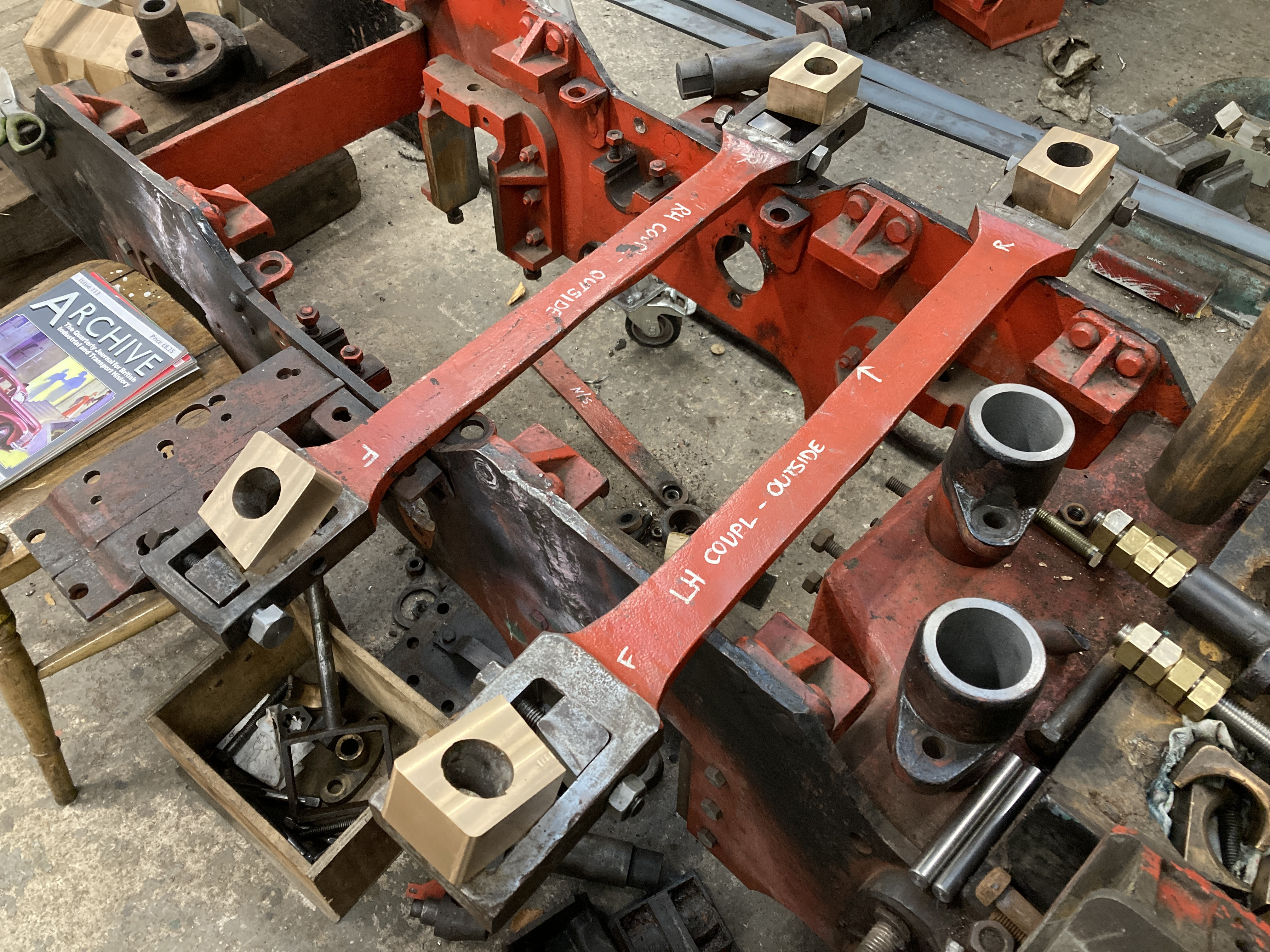
Below: David has also made new coupling rod brasses – these will be machined to the final dimensions of the crankpins in due course.
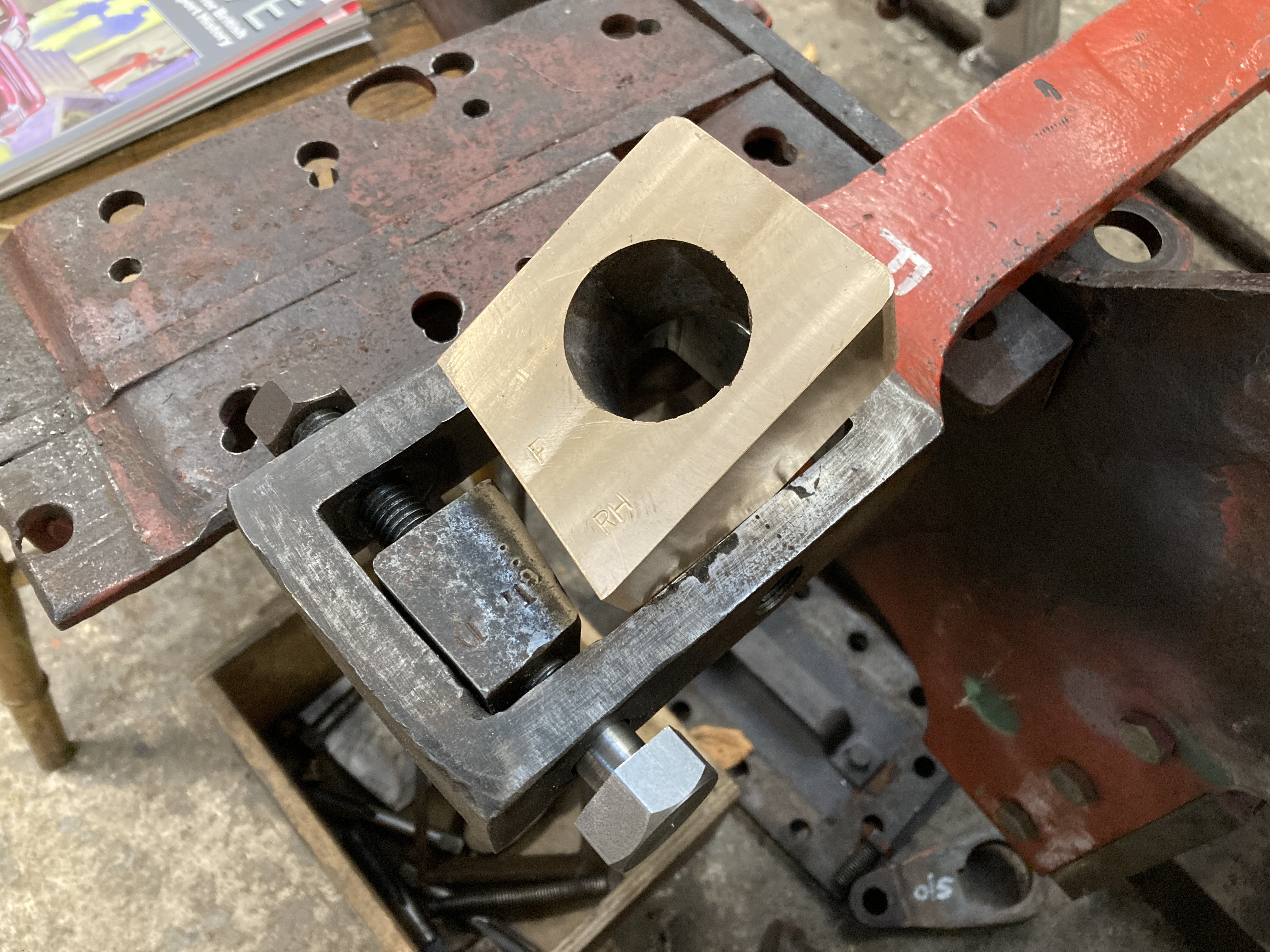
Below: The coupling rods, with their new brasses sat atop them. The connecting rods will also have new brasses, machined from stock material rather than a casting.
Over in the John Fowler works in Bouth, Alex Sharphouse and team have been working on the boiler, inserting the D patch into the barrel and fitting the new front tubeplate and manufacturing a new steam pipe.
As a reminder of 721’s history, I include this link to the article that I wrote for Heritage Railway Magazine, which appears here courtesy of Robin Jones, the magazine editor.
http://beamishtransportonline.co.uk/wp-content/uploads/2022/02/SKM_C224e21061818370.pdf
Gateshead 10
Below: As many as seven people per day have been working on Gateshead 10 – with contract painting, in-house painting, engineering staff and some of the tramway staff all working on elements of its overhaul. Some of the tramway staff have been deployed to work on cleaning and painting the underside of the body, whilst the bogie overhaul continues across the depot.
Below: In order to carry on priming in the colder temperatures, John has set up a tent, which can be warmed through to create a suitable working environment for the further application of paint – in this case applying white undercoat to the roker panel.

Other work in progress
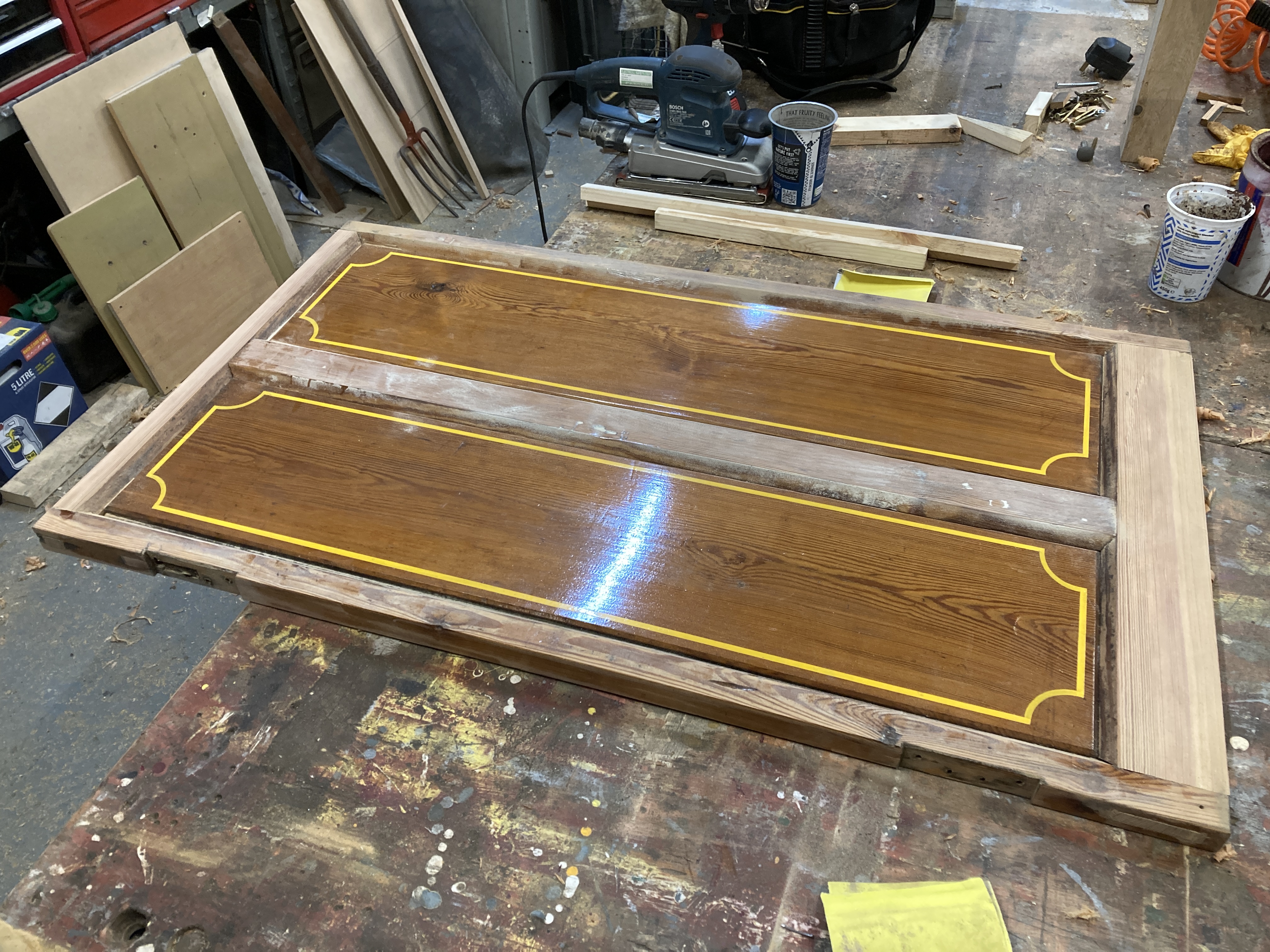
Below: Modifications are being made to the Brampton coach that operates at the Waggonway, to improve the door width and enable access to the passenger compartment for visitors using wheelchairs. This is needed for 2023 as the semi-open coach (latterly painted green and which only had one of the three compartments available for use) is now retired. It will be dismantled and rebuilt into a new guise, reflecting something of the S&DR style, but with more space and continuing to accommodate wheelchairs. The body of that coach has been on borrowed time for a while now, and whilst it has been reinforced and strengthened, there is no getting away from the fact that it really was in need of substantial reconstruction. The Brampton coach modifications will be completed in time for resumption of Waggonway operation at Easter 2023.
Bus and Tram operations
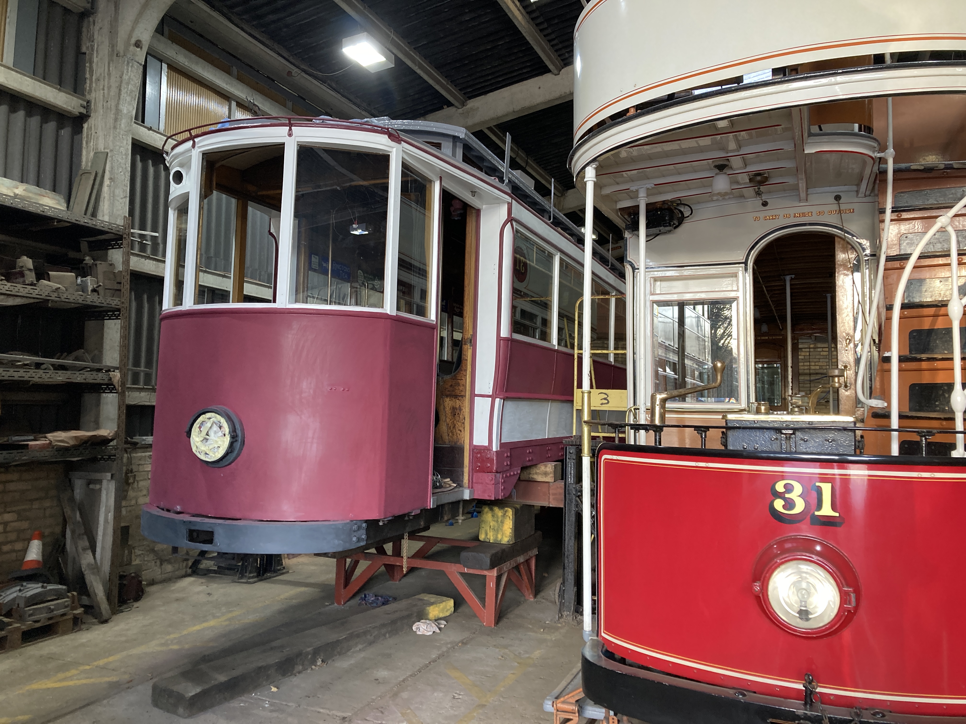
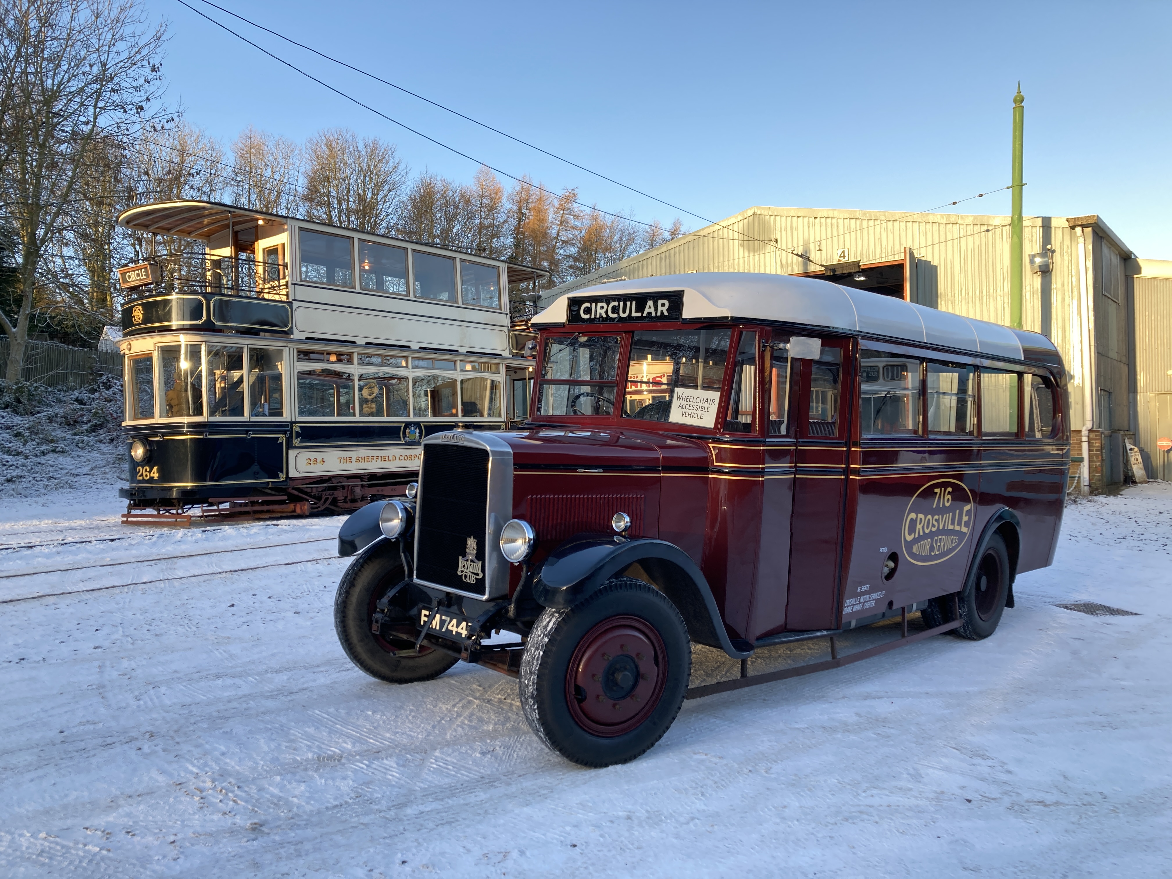
Below: Despite the weather, the site has remained functional with both tram and bus services operating each day that we are open. Here is Sheffield 264 being prepared for service (Sunderland 16 is, for obvious reasons) the second tram in use during the present weather.

Below: Crosville 716 has been in service each day, alongside (usually) Darlington 4 (now with lighting renewed). Rotherham 220 has joined in for evening events.
Below: TMT 11 still awaits its new tyres before the complicated shunt to place it into store is completed. Alongside it, here, is the Aycliffe & District Bus Preservation Society’s 1968 Bristol LH (initially Southern Vectis, and from 1978, United Automobile Services), which has been hired in (with driver) to assist with the museum’s evening Christmas events. Covering daytime operations, as well as the evening shifts, coupled with pressure created by staff sickness, means that the Bristol provides additional capacity that is vital for these busy events. Whilst it is rather ‘modern’ from a curatorial point of view, having doors does mean it can be kept outside when not in use.
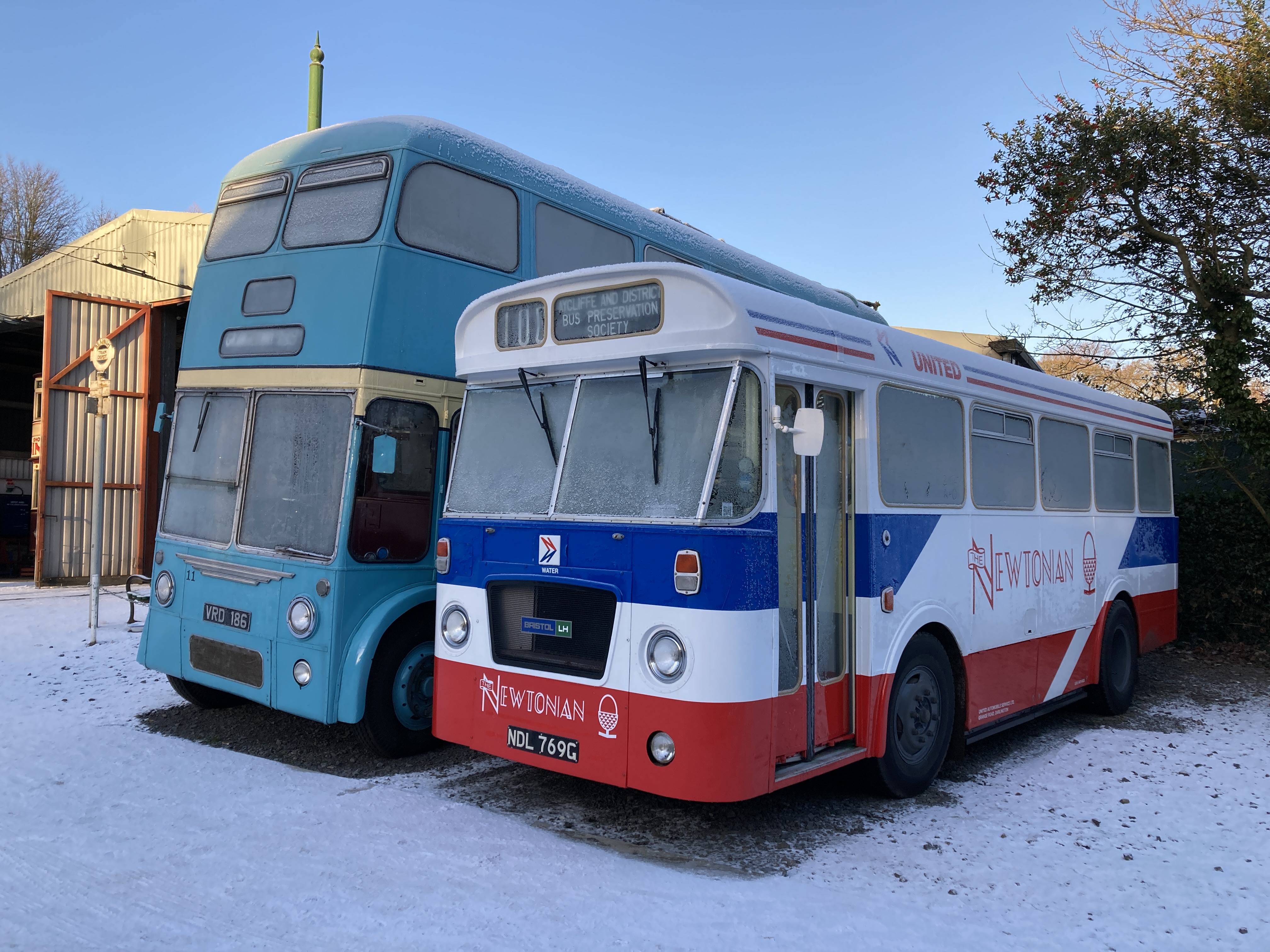
By the end of Tuesday this week, TMT 11 was sat on its new tyres, tucked up in the tram depot, whilst the Bristol had returned home to its owner’s depot.
Waggonway
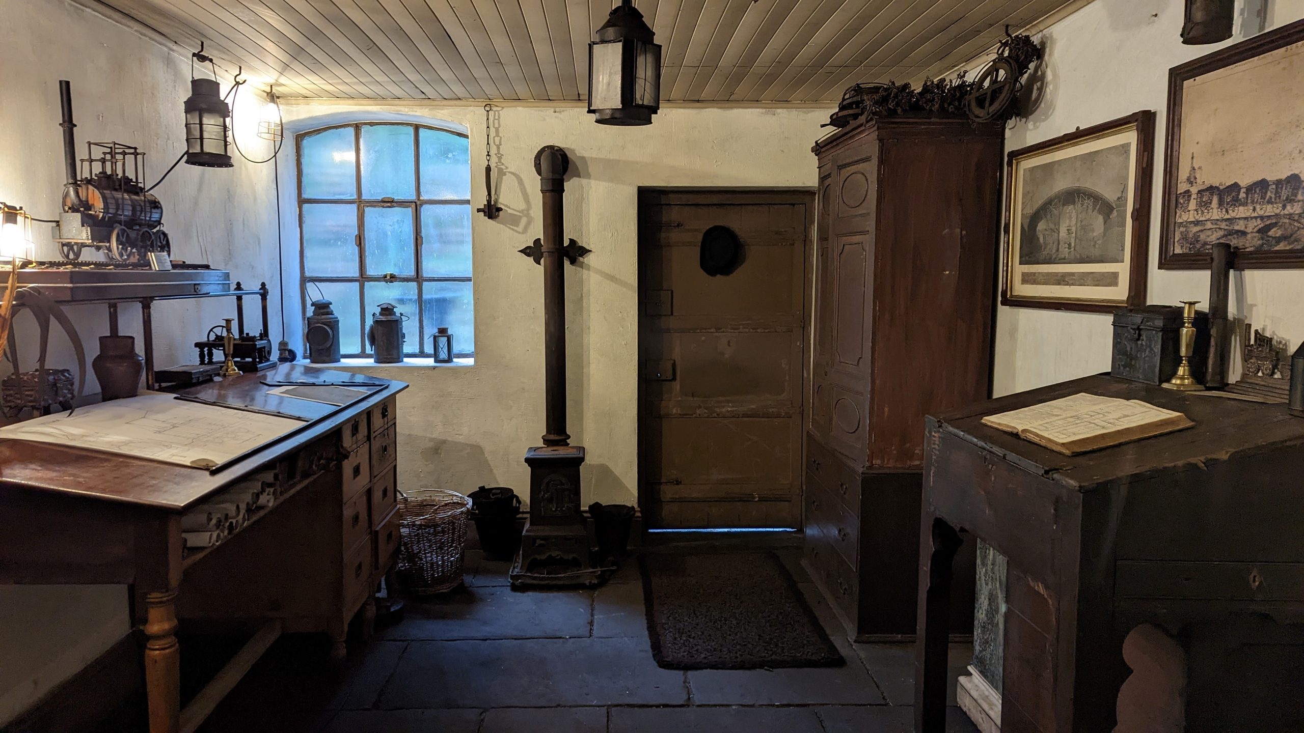
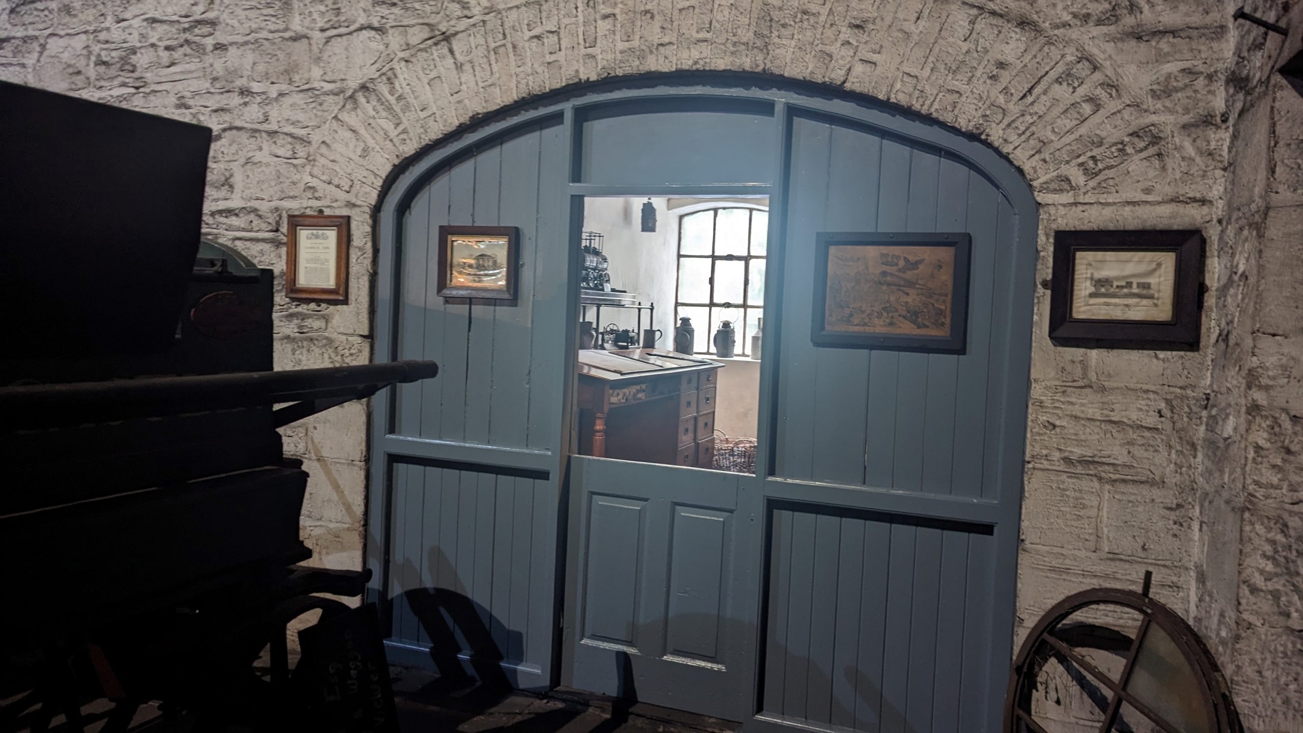
Below: The team have completed their work on the engineer’s bothy – and I’ve included again the photo of the interior as well as a new one showing the external view as well – the aim being to try and keep the space cleaner, by separation from the shed dust and dirt that accumulates there.
Below: The covered Waggonway coach has moved (on Tuesday) to North Bay Railway Engineering Services as part of a plan to reconstruct it, in a revised (and more robust) form, with a view to returning it to service by 2025. Originally an open-coach, the roof was added to provide some protection against the weather, but some inherent weakness in the design of the sides meant that there was constant need of maintenance to ensure the doors closed properly. The side stiffening pieces were added as a last-resort in order to extract one more season’s use from it, and only the centre compartment remained in use. It was painted green in recognition of the colours carried by the Wellington Coach, on the Londonderry Railway. It’s rebuilt form will take it back to Stockton & Darlington Railway guise and, as ever, the process of re-design and reconstruction will be documented here.

Permanent Way
Below: The newly-expanded team have been focussed on re-sleepering between Pockerley and Town East on the Tramway, installing around 50 more plastic sleepers in this area. A similar number more will be put in early in 2023, which will also see some of the worn curved rails in the Town replaced, before work on Bog Bend’s rail-renewal commences. The Tramway will remain the focus of attention for a little while yet, alongside work elsewhere on site.

Colliery Winding Engine
We’ve not seen much of this engine on the blog in recent years, and it sat out quite a bit of the COVID-19 era of operation for various reasons. Its maintenance has now been brought into the engineering team’s remit and they have been carrying out some repairs and adjustments as a result of it being taken out of service with some faults that were preventing it from starting, even in its preferred position with the piston at the top of its stroke. We will cover this in more detail in future posts but here are some photos to round off 2022.
Don Cook, Beamish’s Engineering Supervisor explains:
To start with it had been assumed the problem lay with the reducer valves [Pressure Reducing Vavles – PRV], because as soon as the regulator was opened the line pressure would drop to about 2 psi! The first thing we did was change two gaskets on the regulator, this, as it turned out didn’t make any difference but it did need doing (see photos below). When I watched the engine trying to start and the steam line pressure drop, I noticed a lot of steam going straight up the exhaust flue. This told me there wasn’t a problem with the reducer valve, but the engine itself.
With the cylinder drain cocks open and the engine trying to start, I determined the piston rings were fine, all be it I only had 2 psi to play with to determine this!
This now meant the valves must be at fault. So, with three levels of scaffolding in place, we now remove all four valve covers. Then we turned the engine over, which is easier said than done, and checked the valve events. It turns out the top valves are fine, but both the inlet and exhaust valves on the bottom of the cylinder are not closing fully, so about 90% of the available steam is going straight to the exhaust. It is a wonder the engine managed to run at all!
The next time we visited the Winder I wanted to turn the engine over, but first I want to make sure the valve gear was free. I noticed something was restricting the valve gear’s free movement and upon closer inspection we could see it was ice that had formed in the bottom steam chest cover. This was stopping the valve spindle moving down. This must have happened in the past, as both covers have had their bolts pulled out of the castings. I now intend to fit these with drain cocks to prevent water accumulating and freezing when the engine is out of steam.
Below: The regulator valve – this required new gaskets fitting, for which the main steam pipe outside had to be eased upwards to improve the fit of these.
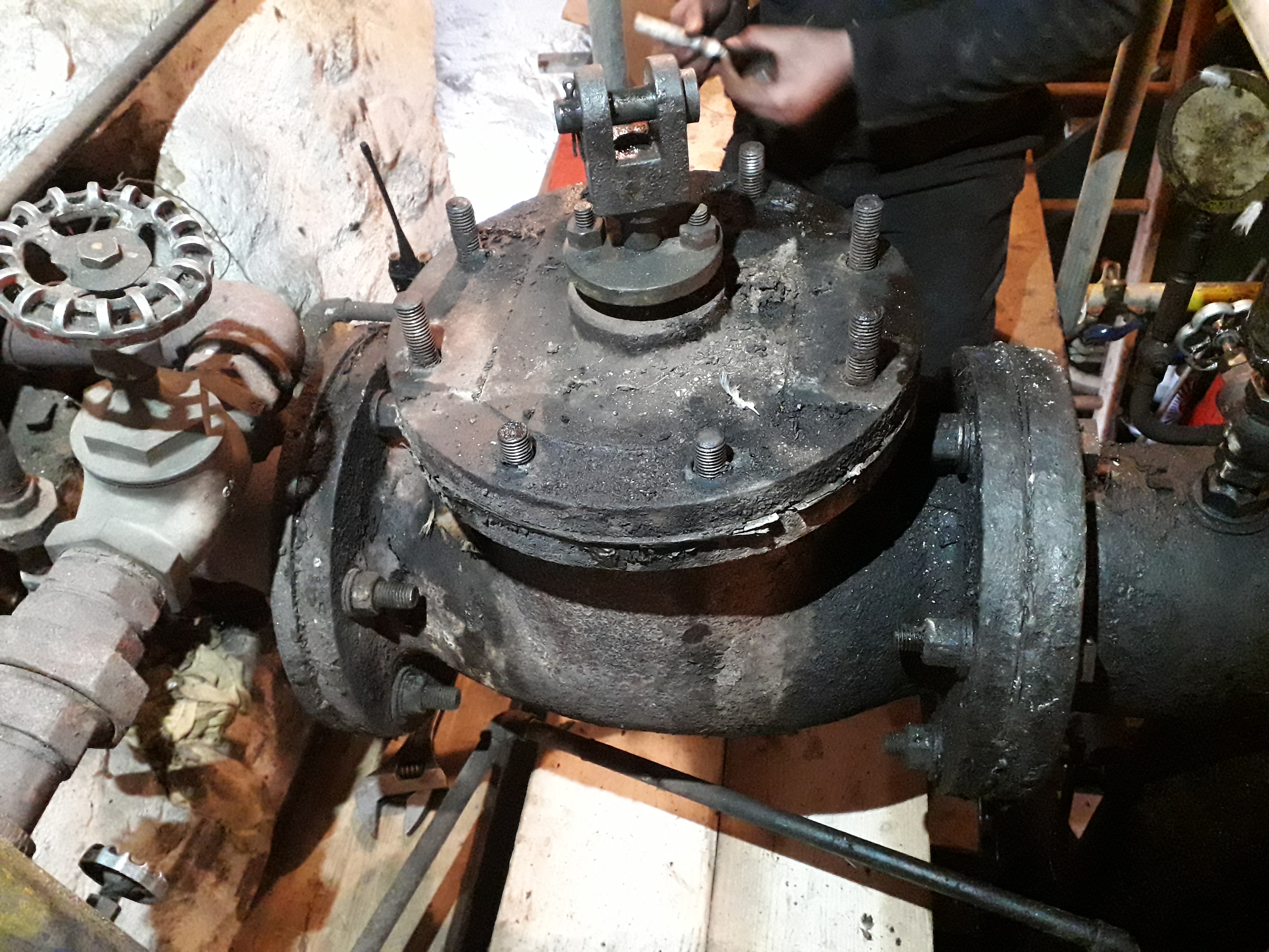
Below: The regulator, with cover removed. To work safely around the engine has necessitated scaffolding it locally, to provide a working platform.
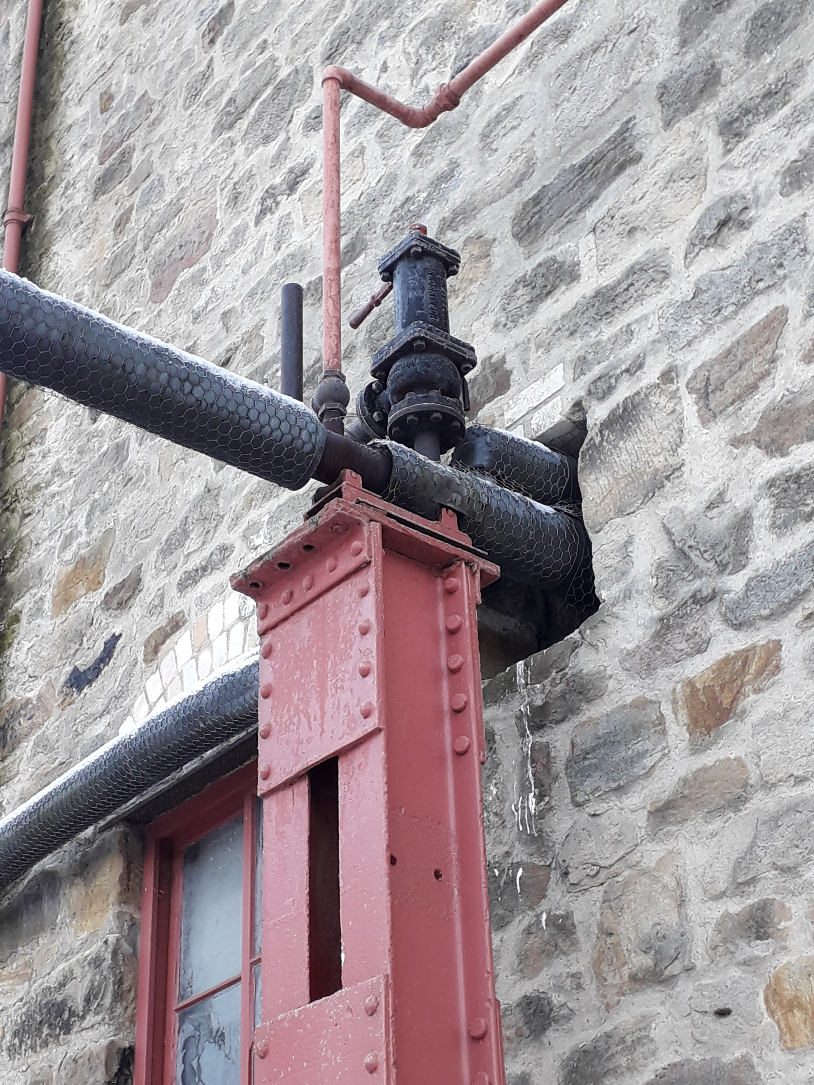
Below: This is where the main steam pipe enters the engine house, complete with safety valve. The steam is restricted to reduce the pressure, the engine not now needing the power to haul cages up and down the shaft.
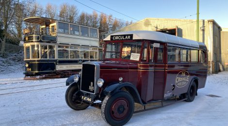
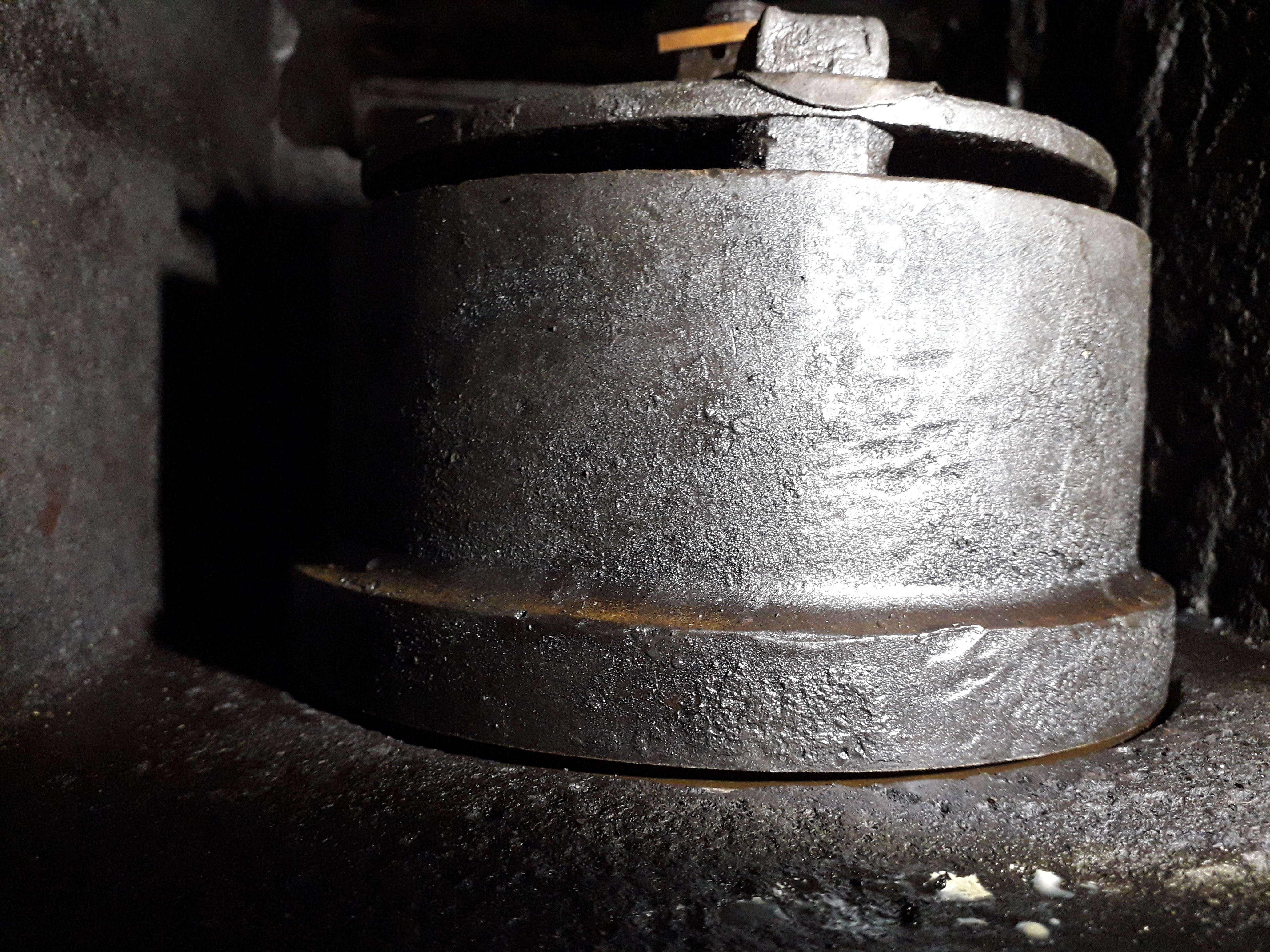
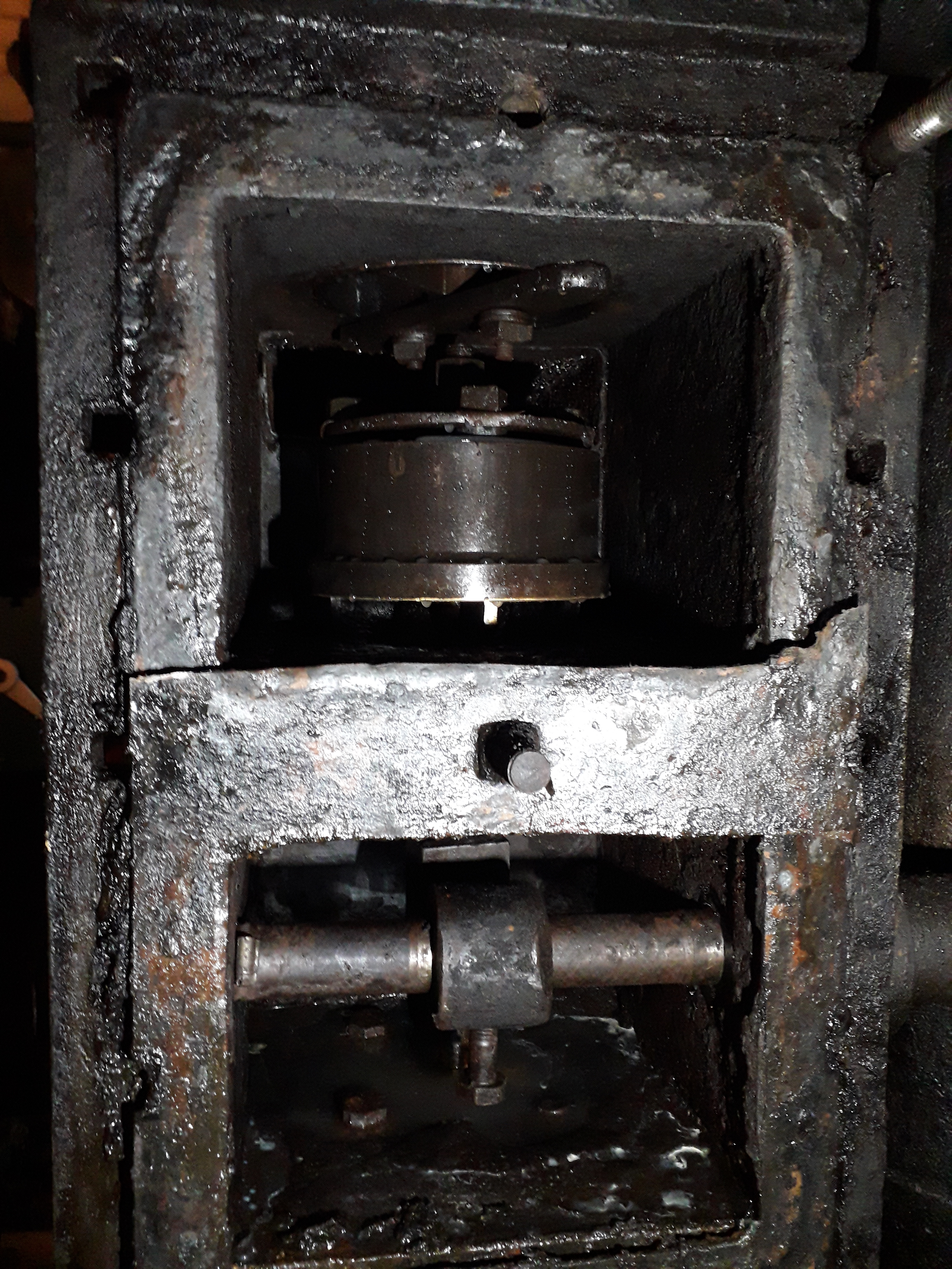
Below: This photo shows the lower steam chest exhaust valve in the closed position, but is still open by about 1/8inch as revealed by the gap at the bottom of the valve.
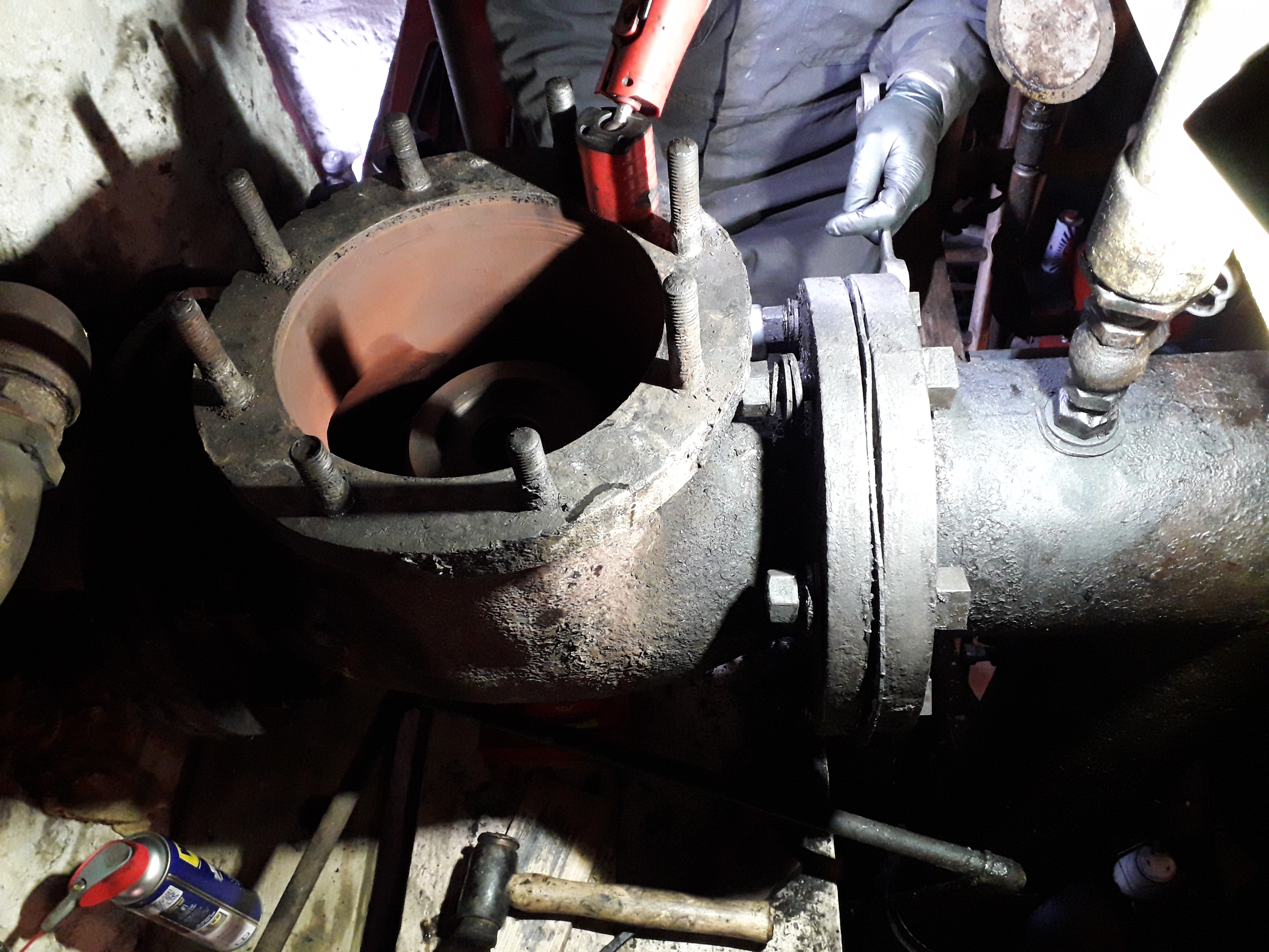
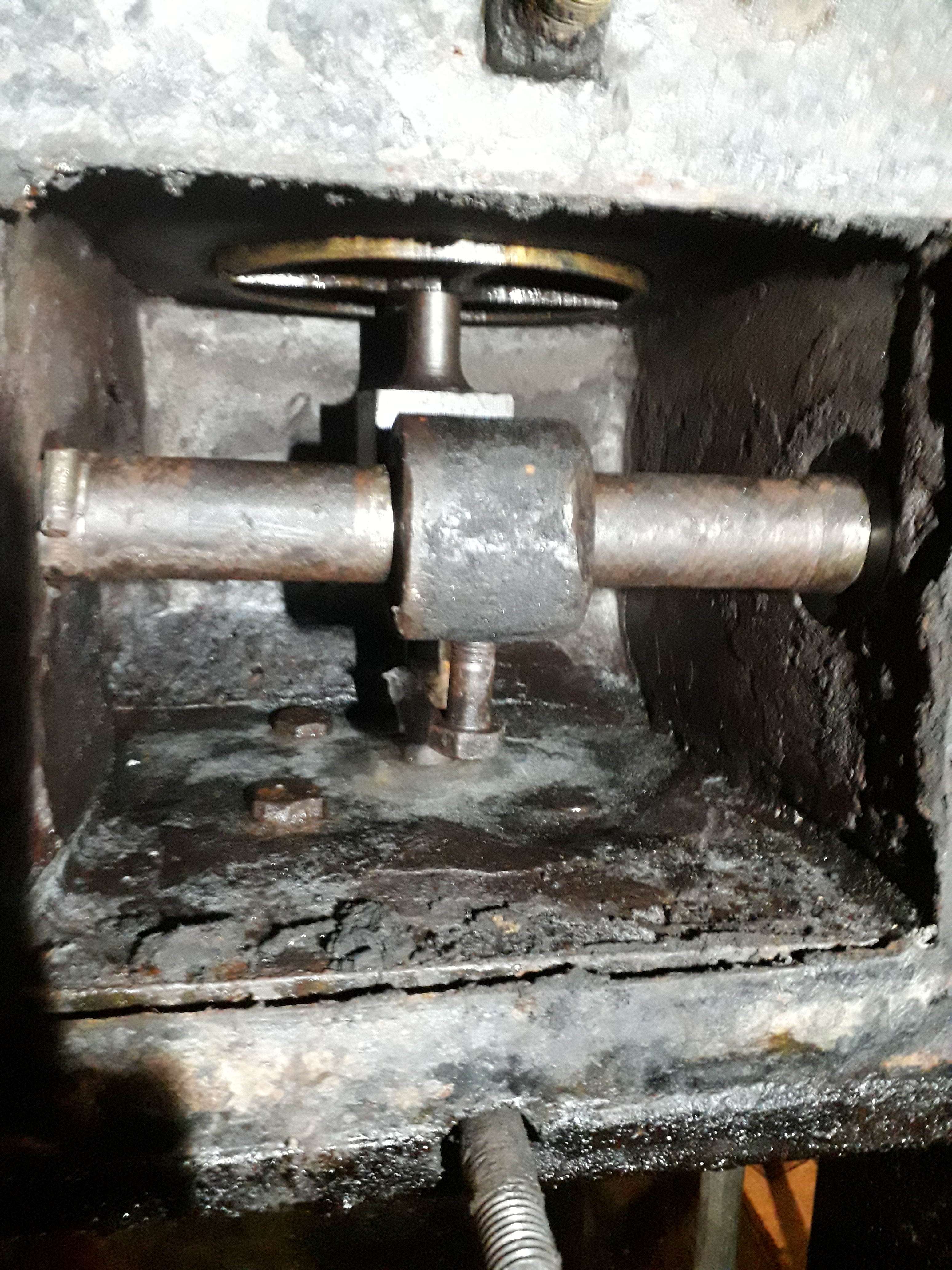
Below: This is the lower steam chest, with the valve fully open. The valve is the piston that you can see in this upper portion of this view.
Below: The upper steam chest, with the valve fully closed – the piston shape is at the rear of the chamber in this view. Note the photo is on its side! I’ve never found a quick way to rotate images in WordPress – it remains a mystery that the editing feature does not work!

Below: This photo shows the bottom cover of the top steam chest full of ice, as referred to by Don in the text above.
Photos above courtesy of Don Cook
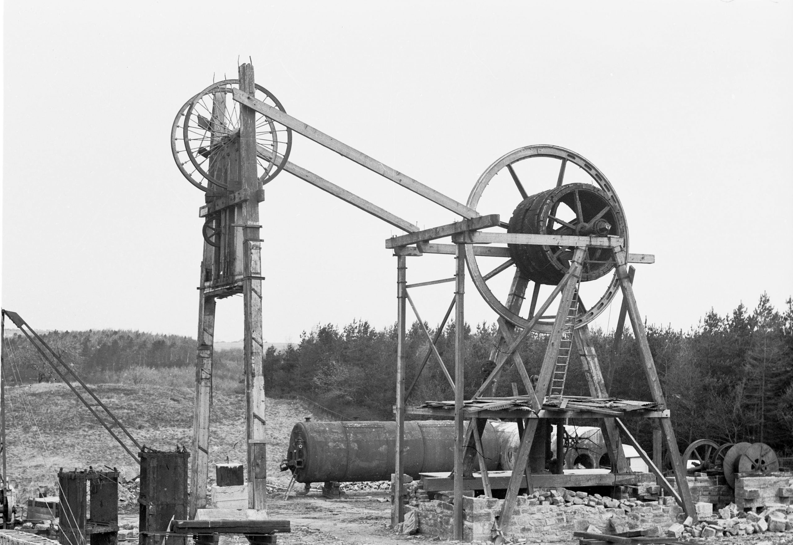
Below: This photo from the archive shows the engine being re-erected at Beamish, and clearly demonstrates how the engine frame is integral with the engin house itself. To the left is the winding drum and flywheel, below which you can just make out the cylinder standing vertically. The engine is of the distinctive design used on the Durham Coalfield, being of the Crowther type – the patent for which explains that the object Jove was to dispense with the beam, placing the crankshaft above the cylinder and guiding the crosshead through the use of parallel motion. So whilst there is a vertical cylinder, there is not the usual beam above the engine as might be the case in many similar applications. Our engine was manufactured in 1855 by J & G Joicey in Newcastle, works No.20. The cylinder is 24 inches in diameter with a bore height of five feet. It was installed at Beamish 2nd Pit, a little to the south if the present museum entrance.
This was the last of the traditional timber-framed vertical engines in use on the coalfield and it was later saved from demolition by Frank Atkinson who had it listed – it was later moved the very short distance to the museum, its original location being just to the left as you drive into the museum from the A693 (what is now a small public car park). This is certainly one of the most important objects in the collection at Beamish and it forms a core part of what we wish to ensure is kept in safe and curatorially appropriate working order.


Bowing out (from 2022) in style! A superb Transport Online news bulletin. Thanks for all the past (and current) information. It really is appreciated.
Hi I love reading the beamish blog I learn alot from to the operating of beamish when I read it. Is there any updates on transport and steam team and if there going to be recruiting since covid stopped it all from happening many thanks Jamie purvis